1993 CHEVROLET PLYMOUTH ACCLAIM instrument panel
[x] Cancel search: instrument panelPage 2236 of 2438
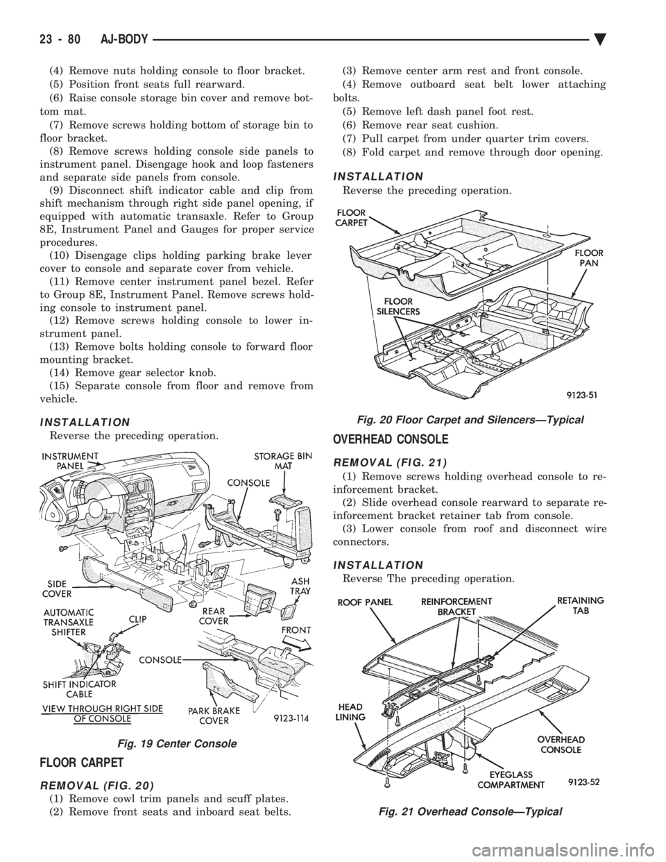
(4) Remove nuts holding console to floor bracket.
(5) Position front seats full rearward.
(6) Raise console storage bin cover and remove bot-
tom mat. (7) Remove screws holding bottom of storage bin to
floor bracket. (8) Remove screws holding console side panels to
instrument panel. Disengage hook and loop fasteners
and separate side panels from console. (9) Disconnect shift indicator cable and clip from
shift mechanism through right side panel opening, if
equipped with automatic transaxle. Refer to Group
8E, Instrument Panel and Gauges for proper service
procedures. (10) Disengage clips holding parking brake lever
cover to console and separate cover from vehicle. (11) Remove center instrument panel bezel. Refer
to Group 8E, Instrument Panel. Remove screws hold-
ing console to instrument panel. (12) Remove screws holding console to lower in-
strument panel. (13) Remove bolts holding console to forward floor
mounting bracket. (14) Remove gear selector knob.
(15) Separate console from floor and remove from
vehicle.
INSTALLATION
Reverse the preceding operation.
FLOOR CARPET
REMOVAL (FIG. 20)
(1) Remove cowl trim panels and scuff plates.
(2) Remove front seats and inboard seat belts. (3) Remove center arm rest and front console.
(4) Remove outboard seat belt lower attaching
bolts. (5) Remove left dash panel foot rest.
(6) Remove rear seat cushion.
(7) Pull carpet from under quarter trim covers.
(8) Fold carpet and remove through door opening.
INSTALLATION
Reverse the preceding operation.
OVERHEAD CONSOLE
REMOVAL (FIG. 21)
(1) Remove screws holding overhead console to re-
inforcement bracket. (2) Slide overhead console rearward to separate re-
inforcement bracket retainer tab from console. (3) Lower console from roof and disconnect wire
connectors.
INSTALLATION
Reverse The preceding operation.
Fig. 19 Center Console
Fig. 20 Floor Carpet and SilencersÐTypical
Fig. 21 Overhead ConsoleÐTypical
23 - 80 AJ-BODY Ä
Page 2254 of 2438
ing hood, align all marks and secure bolts. The hood
should be aligned to 4 mm (0.160 in.) gap to the front
fenders and flush across the top surfaces along fend-
ers.(4) Remove the top hood to hinge attaching bolts
and loosen the bottom bolts until they can be re-
moved by hand. (5) With assistance of a helper at the opposite side
of the vehicle to support the hood, remove the bottom
hood to hinge attaching bolts. Separate the hood
from the vehicle.
HOOD INSTALLATION
Reverse the preceding operation.
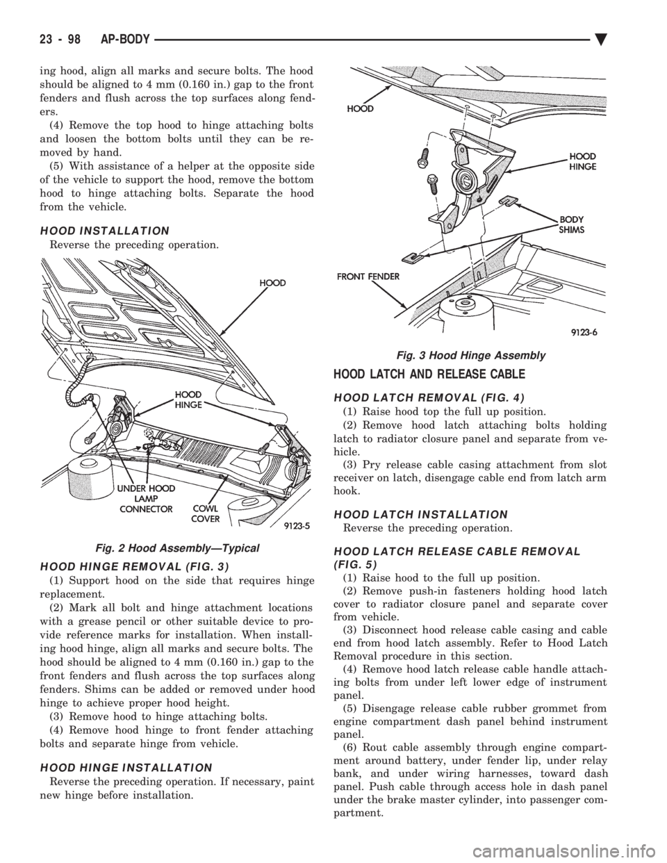
HOOD HINGE REMOVAL (FIG. 3)
(1) Support hood on the side that requires hinge
replacement. (2) Mark all bolt and hinge attachment locations
with a grease pencil or other suitable device to pro-
vide reference marks for installation. When install-
ing hood hinge, align all marks and secure bolts. The
hood should be aligned to 4 mm (0.160 in.) gap to the
front fenders and flush across the top surfaces along
fenders. Shims can be added or removed under hood
hinge to achieve proper hood height. (3) Remove hood to hinge attaching bolts.
(4) Remove hood hinge to front fender attaching
bolts and separate hinge from vehicle.
HOOD HINGE INSTALLATION
Reverse the preceding operation. If necessary, paint
new hinge before installation.
HOOD LATCH AND RELEASE CABLE
HOOD LATCH REMOVAL (FIG. 4)
(1) Raise hood top the full up position.
(2) Remove hood latch attaching bolts holding
latch to radiator closure panel and separate from ve-
hicle. (3) Pry release cable casing attachment from slot
receiver on latch, disengage cable end from latch arm
hook.
HOOD LATCH INSTALLATION
Reverse the preceding operation.
HOOD LATCH RELEASE CABLE REMOVAL (FIG. 5)
(1) Raise hood to the full up position.
(2) Remove push-in fasteners holding hood latch
cover to radiator closure panel and separate cover
from vehicle. (3) Disconnect hood release cable casing and cable
end from hood latch assembly. Refer to Hood Latch
Removal procedure in this section. (4) Remove hood latch release cable handle attach-
ing bolts from under left lower edge of instrument
panel. (5) Disengage release cable rubber grommet from
engine compartment dash panel behind instrument
panel. (6) Rout cable assembly through engine compart-
ment around battery, under fender lip, under relay
bank, and under wiring harnesses, toward dash
panel. Push cable through access hole in dash panel
under the brake master cylinder, into passenger com-
partment.
Fig. 2 Hood AssemblyÐTypical
Fig. 3 Hood Hinge Assembly
23 - 98 AP-BODY Ä
Page 2269 of 2438
REAR SEAT BACK INSTALLATION
Reverse the preceding operation.
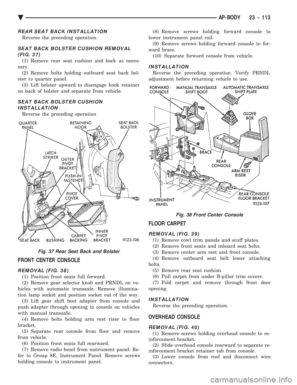
SEAT BACK BOLSTER CUSHION REMOVAL (FIG. 37)
(1) Remove rear seat cushion and back as neces-
sary. (2) Remove bolts holding outboard seat back bol-
ster to quarter panel. (3) Lift bolster upward to disengage hook retainer
on back of bolster and separate from vehicle.
SEAT BACK BOLSTER CUSHION INSTALLATION
Reverse the preceding operation
FRONT CENTER CONSOLE
REMOVAL (FIG. 38)
(1) Position front seats full forward.
(2) Remove gear selector knob and PRNDL on ve-
hicles with automatic transaxle. Remove illumina-
tion lamp socket and position socket out of the way. (3) Lift gear shift boot adapter from console and
push adapter through opening in console on vehicles
with manual transaxle. (4) Remove bolts holding arm rest riser to floor
bracket. (5) Separate rear console from floor and remove
from vehicle. (6) Position front seats full rearward.
(7) Remove radio bezel from instrument panel. Re-
fer to Group 8E, Instrument Panel. Remove screws
holding console to instrument panel. (8) Remove screws holding forward console to
lower instrument panel rail. (9) Remove screws holding forward console to for-
ward brace. (10) Separate forward console from vehicle.
INSTALLATION
Reverse the preceding operation. Verify PRNDL
adjustment before returning vehicle to use.
FLOOR CARPET
REMOVAL (FIG. 39)
(1) Remove cowl trim panels and scuff plates.
(2) Remove front seats and inboard seat belts.
(3) Remove center arm rest and front console.
(4) Remove outboard seat belt lower attaching
bolts. (5) Remove rear seat cushion.
(6) Pull carpet from under B-pillar trim covers.
(7) Fold carpet and remove through front door
opening.
INSTALLATION
Reverse the preceding operation.
OVERHEAD CONSOLE
REMOVAL (FIG. 40)
(1) Remove screws holding overhead console to re-
inforcement bracket. (2) Slide overhead console rearward to separate re-
inforcement bracket retainer tab from console. (3) Lower console from roof and disconnect wire
connectors.
Fig. 37 Rear Seat Back and Bolster
Fig. 38 Front Center Console
Ä AP-BODY 23 - 113
Page 2292 of 2438
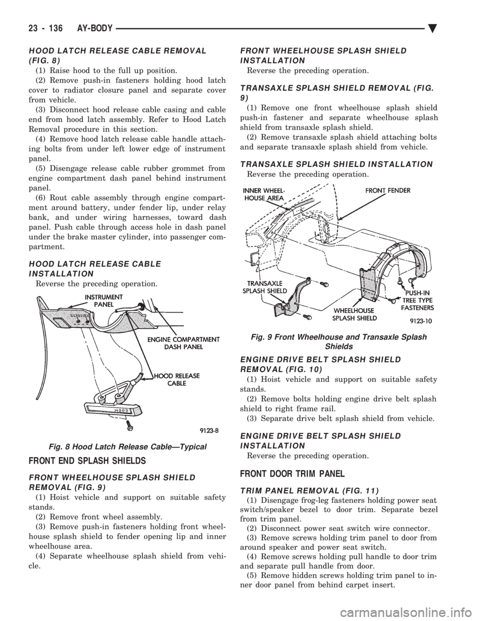
HOOD LATCH RELEASE CABLE REMOVAL (FIG. 8)
(1) Raise hood to the full up position.
(2) Remove push-in fasteners holding hood latch
cover to radiator closure panel and separate cover
from vehicle. (3) Disconnect hood release cable casing and cable
end from hood latch assembly. Refer to Hood Latch
Removal procedure in this section. (4) Remove hood latch release cable handle attach-
ing bolts from under left lower edge of instrument
panel. (5) Disengage release cable rubber grommet from
engine compartment dash panel behind instrument
panel. (6) Rout cable assembly through engine compart-
ment around battery, under fender lip, under relay
bank, and under wiring harnesses, toward dash
panel. Push cable through access hole in dash panel
under the brake master cylinder, into passenger com-
partment.
HOOD LATCH RELEASE CABLE INSTALLATION
Reverse the preceding operation.
FRONT END SPLASH SHIELDS
FRONT WHEELHOUSE SPLASH SHIELDREMOVAL (FIG. 9)
(1) Hoist vehicle and support on suitable safety
stands. (2) Remove front wheel assembly.
(3) Remove push-in fasteners holding front wheel-
house splash shield to fender opening lip and inner
wheelhouse area. (4) Separate wheelhouse splash shield from vehi-
cle.
FRONT WHEELHOUSE SPLASH SHIELD INSTALLATION
Reverse the preceding operation.
TRANSAXLE SPLASH SHIELD REMOVAL (FIG.9)
(1) Remove one front wheelhouse splash shield
push-in fastener and separate wheelhouse splash
shield from transaxle splash shield. (2) Remove transaxle splash shield attaching bolts
and separate transaxle splash shield from vehicle.
TRANSAXLE SPLASH SHIELD INSTALLATION
Reverse the preceding operation.
ENGINE DRIVE BELT SPLASH SHIELD REMOVAL (FIG. 10)
(1) Hoist vehicle and support on suitable safety
stands. (2) Remove bolts holding engine drive belt splash
shield to right frame rail. (3) Separate drive belt splash shield from vehicle.
ENGINE DRIVE BELT SPLASH SHIELDINSTALLATION
Reverse the preceding operation.
FRONT DOOR TRIM PANEL
TRIM PANEL REMOVAL (FIG. 11)
(1) Disengage frog-leg fasteners holding power seat
switch/speaker bezel to door trim. Separate bezel
from trim panel. (2) Disconnect power seat switch wire connector.
(3) Remove screws holding trim panel to door from
around speaker and power seat switch. (4) Remove screws holding pull handle to door trim
and separate pull handle from door. (5) Remove hidden screws holding trim panel to in-
ner door panel from behind carpet insert.
Fig. 8 Hood Latch Release CableÐTypical
Fig. 9 Front Wheelhouse and Transaxle Splash Shields
23 - 136 AY-BODY Ä
Page 2305 of 2438
HEATING AND AIR CONDITIONING
CONTENTS
page page
AUTOMATIC TEMPERATURE CONTROL (ATC) .............................. 66
COMPONENT SERVICE PROCEDURES ...... 47
FIXED DISPLACEMENT COMPRESSORÐ MODEL 10PA17 ...................... 24
FIXED DISPLACEMENT COMPRESSORÐ MODEL SD709P ...................... 38 FIXED DISPLACEMENT COMPRESSORÐ
MODEL TR105 ....................... 32
GENERAL INFORMATION .................. 1
HEATER AND A/C PERFORMANCE TESTS .... 6
REFRIGERANT SERVICE PROCEDURES ...... 8
VACUUM CONTROL SYSTEM DIAGNOSIS .... 4
VARIABLE DISPLACEMENT COMPRESSORÐ MODEL 6C17 ......................... 13
GENERAL INFORMATION INDEX
page page
A/C System Identification ................... 1
Cooling System Precautions ................. 3
Description and Operation ................... 1
Engine Cooling System Requirements .......... 2 Handling Tubing and Fittings
................. 3
Safety Precautions and Warnings ............. 3
Side Window Demisters .................... 2
System Airflow ........................... 1
A/C SYSTEM IDENTIFICATION
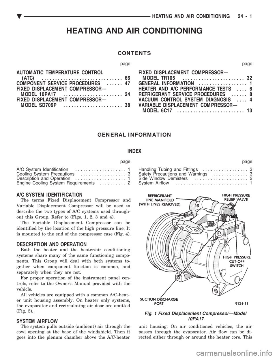
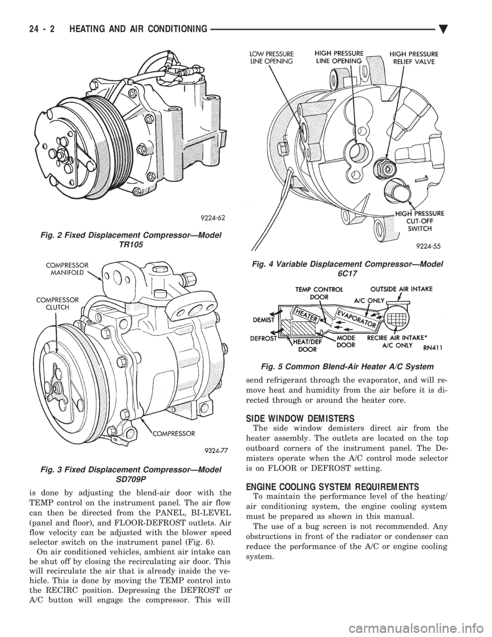
The terms Fixed Displacement Compressor and
Variable Displacement Compressor will be used to
describe the two types of A/C systems used through-
out this Group. Refer to (Figs. 1, 2, 3 and 4). The Variable Displacement Compressor can be
identified by the location of the high pressure line. It
is mounted to the end of the compressor case (Fig. 4).
DESCRIPTION AND OPERATION
Both the heater and the heater/air conditioning
systems share many of the same functioning compo-
nents. This Group will deal with both systems to-
gether when component function is common, and
separately when they are not. For proper operation of the instrument panel con-
trols, refer to the Owner's Manual provided with the
vehicle. All vehicles are equipped with a common A/C-heat-
er unit housing assembly. On heater only systems,
the evaporator and recirculating air door are omitted
(Fig. 5).
SYSTEM AIRFLOW
The system pulls outside (ambient) air through the
cowl opening at the base of the windshield. Then it
goes into the plenum chamber above the A/C-heater unit housing. On air conditioned vehicles, the air
passes through the evaporator. Air flow can be di-
rected either through or around the heater core. This
Fig. 1 Fixed Displacement CompressorÐModel 10PA17
Ä HEATING AND AIR CONDITIONING 24 - 1
Page 2306 of 2438
is done by adjusting the blend-air door with the
TEMP control on the instrument panel. The air flow
can then be directed from the PANEL, BI-LEVEL
(panel and floor), and FLOOR-DEFROST outlets. Air
flow velocity can be adjusted with the blower speed
selector switch on the instrument panel (Fig. 6). On air conditioned vehicles, ambient air intake can
be shut off by closing the recirculating air door. This
will recirculate the air that is already inside the ve-
hicle. This is done by moving the TEMP control into
the RECIRC position. Depressing the DEFROST or
A/C button will engage the compressor. This will send refrigerant through the evaporator, and will re-
move heat and humidity from the air before it is di-
rected through or around the heater core.
SIDE WINDOW DEMISTERS
The side window demisters direct air from the
heater assembly. The outlets are located on the top
outboard corners of the instrument panel. The De-
misters operate when the A/C control mode selector
is on FLOOR or DEFROST setting.
ENGINE COOLING SYSTEM REQUIREMENTS
To maintain the performance level of the heating/
air conditioning system, the engine cooling system
must be prepared as shown in this manual. The use of a bug screen is not recommended. Any
obstructions in front of the radiator or condenser can
reduce the performance of the A/C or engine cooling
system.
Fig. 2 Fixed Displacement CompressorÐModel TR105
Fig. 3 Fixed Displacement CompressorÐModelSD709P
Fig. 4 Variable Displacement CompressorÐModel 6C17
Fig. 5 Common Blend-Air Heater A/C System
24 - 2 HEATING AND AIR CONDITIONING Ä
Page 2308 of 2438
VACUUM CONTROL SYSTEM DIAGNOSIS
GENERAL INFORMATION
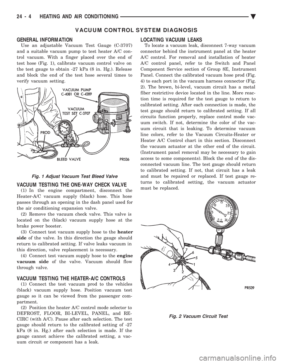
Use an adjustable Vacuum Test Gauge (C-3707)
and a suitable vacuum pump to test heater A/C con-
trol vacuum. With a finger placed over the end of
test hose (Fig. 1), calibrate vacuum control valve on
the test gauge to obtain -27 kPa (8 in. Hg.). Release
and block the end of the test hose several times to
verify vacuum setting.
VACUUM TESTING THE ONE-WAY CHECK VALVE
(1) In the engine compartment, disconnect the
Heater-A/C vacuum supply (black) hose. This hose
passes through an opening in the dash panel used for
the air conditioning expansion valve. (2) Remove the vacuum check valve. This valve is
located on the (black) vacuum supply hose at the
brake power booster. (3) Connect test vacuum supply hose to the heater
side of the valve. In this direction the gauge should
return to calibrated setting. If valve leaks vacuum in
this direction, valve replacement is necessary. (4) Connect test vacuum supply hose to the engine
vacuum side of the valve. Vacuum should flow
through valve.
VACUUM TESTING THE HEATER-A/C CONTROLS
(1) Connect the test vacuum prod to the vehicles
(black) vacuum supply hose. Position vacuum test
gauge so it can be viewed from the passenger com-
partment. (2) Position the heater A/C control mode selector to
DEFROST, FLOOR, BI-LEVEL, PANEL, and RE-
CIRC (with A/C). Pause after each selection. The test
gauge should return to the calibrated setting of -27
kPa (8 in. Hg.) after each selection is made. If the
gauge cannot achieve the calibrated setting, a vac-
uum circuit or component has a leak.
LOCATING VACUUM LEAKS
To locate a vacuum leak, disconnect 7-way vacuum
connector behind the instrument panel at the heater
A/C control. For removal and installation of heater
A/C control panel, refer to the Switch and Panel
Component Service section of Group 8E, Instrument
Panel. Connect the calibrated vacuum hose prod (Fig.
4) to each port in the vacuum harness connector (Fig.
2). The brown, bi-level, vacuum circuit has a metal
fiber restrictive device located in the line. More reac-
tion time is required for the test gauge to return to
calibrated setting. After each connection is made, the
test gauge should return to calibrated setting. If all
circuits function properly, replace control mode vac-
uum switch. If not, determine the color of the vac-
uum circuit that is leaking. To determine vacuum
line colors, refer to the Vacuum Circuits-Heater or
Heater A/C Control chart in this section. Disconnect
the vacuum actuator at the other end of the circuit.
(Instrument panel removal may be necessary to gain
access to some components). Block the end of the dis-
connected vacuum line. The test gauge should return
to calibrated setting. If not, that circuit has a leak
and must be repaired or replaced. If test gauge re-
turns to calibrated setting, the vacuum actuator
must be replaced.
Fig. 1 Adjust Vacuum Test Bleed Valve
Fig. 2 Vacuum Circuit Test
24 - 4 HEATING AND AIR CONDITIONING Ä
Page 2310 of 2438
HEATER AND A/C PERFORMANCE TESTS
HEATER OUTPUT TEST
PRE-DIAGNOSTIC PREPARATIONS
Review Safety Precautions and Warnings before
performing the following procedures. Check the radiator coolant level, drive belt tension,
and engine vacuum line connections. Also check ra-
diator air flow and radiator fan operation. Start en-
gine and allow to warm up to normal operating
temperature.
WARNING: DO NOT REMOVE RADIATOR CAP
WHEN ENGINE IS HOT, PERSONAL INJURY CAN
RESULT.
If vehicle has been run recently, wait 15 minutes
before removing cap. Place a rag over the cap and
turn it to the first safety stop. Allow pressure to es-
cape through the overflow tube. When the system
stabilizes, remove the cap completely.
MAXIMUM HEATER OUTPUT: TEST AND ACTION
Engine coolant is provided to the heater system by
two 16 mm (5/8 inch inside diameter) heater hoses.
With engine idling at normal running temperature,
set the control to maximum heat, floor, and high
blower setting. Using a test thermometer, check the
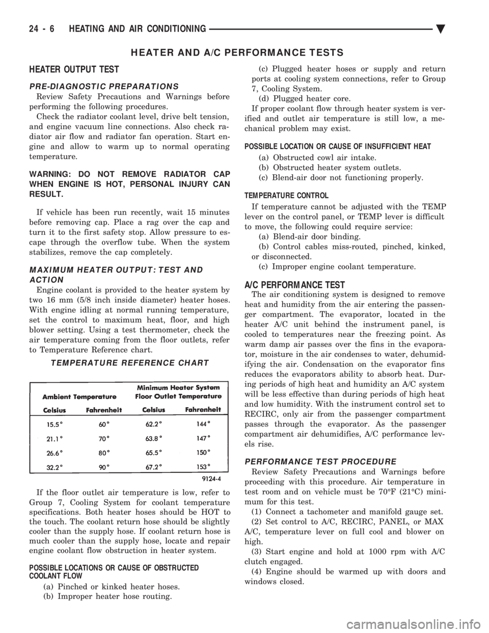
air temperature coming from the floor outlets, refer
to Temperature Reference chart.
If the floor outlet air temperature is low, refer to
Group 7, Cooling System for coolant temperature
specifications. Both heater hoses should be HOT to
the touch. The coolant return hose should be slightly
cooler than the supply hose. If coolant return hose is
much cooler than the supply hose, locate and repair
engine coolant flow obstruction in heater system.
POSSIBLE LOCATIONS OR CAUSE OF OBSTRUCTED
COOLANT FLOW
(a) Pinched or kinked heater hoses.
(b) Improper heater hose routing. (c) Plugged heater hoses or supply and return
ports at cooling system connections, refer to Group
7, Cooling System. (d) Plugged heater core.
If proper coolant flow through heater system is ver-
ified and outlet air temperature is still low, a me-
chanical problem may exist.
POSSIBLE LOCATION OR CAUSE OF INSUFFICIENT HEAT
(a) Obstructed cowl air intake.
(b) Obstructed heater system outlets.
(c) Blend-air door not functioning properly.
TEMPERATURE CONTROL If temperature cannot be adjusted with the TEMP
lever on the control panel, or TEMP lever is difficult
to move, the following could require service: (a) Blend-air door binding.
(b) Control cables miss-routed, pinched, kinked,
or disconnected. (c) Improper engine coolant temperature.A/C PERFORMANCE TEST
The air conditioning system is designed to remove
heat and humidity from the air entering the passen-
ger compartment. The evaporator, located in the
heater A/C unit behind the instrument panel, is
cooled to temperatures near the freezing point. As
warm damp air passes over the fins in the evapora-
tor, moisture in the air condenses to water, dehumid-
ifying the air. Condensation on the evaporator fins
reduces the evaporators ability to absorb heat. Dur-
ing periods of high heat and humidity an A/C system
will be less effective than during periods of high heat
and low humidity. With the instrument control set to
RECIRC, only air from the passenger compartment
passes through the evaporator. As the passenger
compartment air dehumidifies, A/C performance lev-
els rise.
PERFORMANCE TEST PROCEDURE
Review Safety Precautions and Warnings before
proceeding with this procedure. Air temperature in
test room and on vehicle must be 70ÉF (21ÉC) mini-
mum for this test. (1) Connect a tachometer and manifold gauge set.
(2) Set control to A/C, RECIRC, PANEL, or MAX
A/C, temperature lever on full cool and blower on
high. (3) Start engine and hold at 1000 rpm with A/C
clutch engaged. (4) Engine should be warmed up with doors and
windows closed.
TEMPERATURE REFERENCE CHART
24 - 6 HEATING AND AIR CONDITIONING Ä