1993 CHEVROLET PLYMOUTH ACCLAIM instrument panel
[x] Cancel search: instrument panelPage 1903 of 2438
line. However, these could result in a rich or lean
condition causing an oxygen sensor fault to be stored in
the PCM. Secondary Ignition Circuit - The PCM cannot
detect an inoperative ignition coil, fouled or worn spark
plugs, ignition cross firing, or open spark plug cables. Engine Timing - The PCM cannot detect an incor-
rectly indexed timing chain, camshaft sprocket and
crankshaft sprocket. However, these could result in a
rich or lean condition causing an oxygen sensor fault to
be stored in the PCM. Cylinder Compression - The PCM cannot detect
uneven, low, or high engine cylinder compression. Exhaust System - The PCM cannot detect a
plugged, restricted or leaking exhaust system. Fuel Injector Malfunctions - The PCM cannot
determine if a fuel injector is clogged, the needle is
sticking or the wrong injector is installed. However,
these could result in a rich or lean condition causing an
oxygen sensor fault to be stored in the PCM. Excessive Oil Consumption - Although the PCM
monitors exhaust stream oxygen content when the
system is in closed loop, it cannot determine excessive
oil consumption. Throttle Body Air Flow - The PCM cannot detect a
clogged or restricted air cleaner inlet or filter element. Evaporative System - The PCM will not detect a
restricted, plugged or loaded evaporative purge canis-
ter. Vacuum Assist - Leaks or restrictions in the
vacuum circuits of vacuum assisted engine control
system devices are not monitored by the PCM. How-
ever, these could result in a MAP sensor fault being
stored in the PCM. PCM System Ground - The PCM cannot determine
a poor system ground. However, a diagnostic trouble
code may be generated as a result of this condition. PCM Connector Engagement - The PCM cannot
determine spread or damaged connector pins. How-
ever, a diagnostic trouble code may be generated as a
result of this condition.
HIGH AND LOW LIMITS
The powertrain control module (PCM) compares in-
put signal voltages from each input device with estab-
lished high and low limits for the device. If the input
voltage is not within limits and other diagnostic
trouble code criteria are met, a diagnostic trouble code
will be stored in memory. Other diagnostic trouble code
criteria might include engine RPM limits or input
voltages from other sensors or switches that must be
present before a fault condition can be verified.
DIAGNOSTIC TROUBLE CODE DESCRIPTION
A diagnostic trouble code indicates that the power-
train control module (PCM) has recognized an abnor- mal condition in the system. Diagnostic trouble codes
can be obtained from the malfunction indicator lamp
(Check Engine lamp on the instrument panel) or from
the DRBII scan tool. Diagnostic trouble codes indicate
the results of a failure but do not identify the failed
component directly.
SYSTEM TESTS
WARNING: APPLY PARKING BRAKE AND/OR BLOCK
WHEELS BEFORE PERFORMING ANY TEST ON AN
OPERATING ENGINE.
OBTAINING DIAGNOSTIC TROUBLE CODES
(1) Connect the DRBII scan tool to the data link
connector located in the engine compartment near the
driver side strut tower (Fig. 1). (2) Start the engine if possible, cycle the transaxle
selector and the A/Cswitch if applicable. Shut off the
engine. (3) Turn the ignition switch on, access Read Fault
Screen. Record all the fault messages shown on the
DRBII scan tool. Observe the malfunction indicator
lamp (check engine lamp on the instrument panel). The
lamp should light for 2 seconds then go out (bulb
check). Diagnostic trouble code erasure; access erase
diagnostic trouble code data
STATE DISPLAY TEST MODE
The switch inputs used by the powertrain control
module (PCM) have only two recognized states, HIGH
and LOW. For this reason, the PCM cannot recognize
the difference between a selected switch position ver-
sus an open circuit, a short circuit, or a defective
switch. If the change is displayed, it can be assumed
that the entire switch circuit to the PCM is functional.
From the state display screen access either State
Display Inputs and Outputs or State Display Sensors.
STATE DISPLAY INPUTS AND OUTPUTS
Connect the DRBII scan tool to the vehicle and access
the State Display screen. Then access Inputs and
Outputs. The following is a list of the engine control
system functions accessible through the Inputs and
Outputs screen. Park/Neutral Switch
Speed Control Resume
Brake Switch
Speed Control On/Off
Speed Control Set
A/C Switch Sense
S/C Vent Solenoid
Ä FUEL SYSTEMS 14 - 163
Page 2063 of 2438
SPEED SENSOR-OUTPUT
CAUTION: When disconnecting speed sensor con-
nector, be sure that the weather seal does not fall
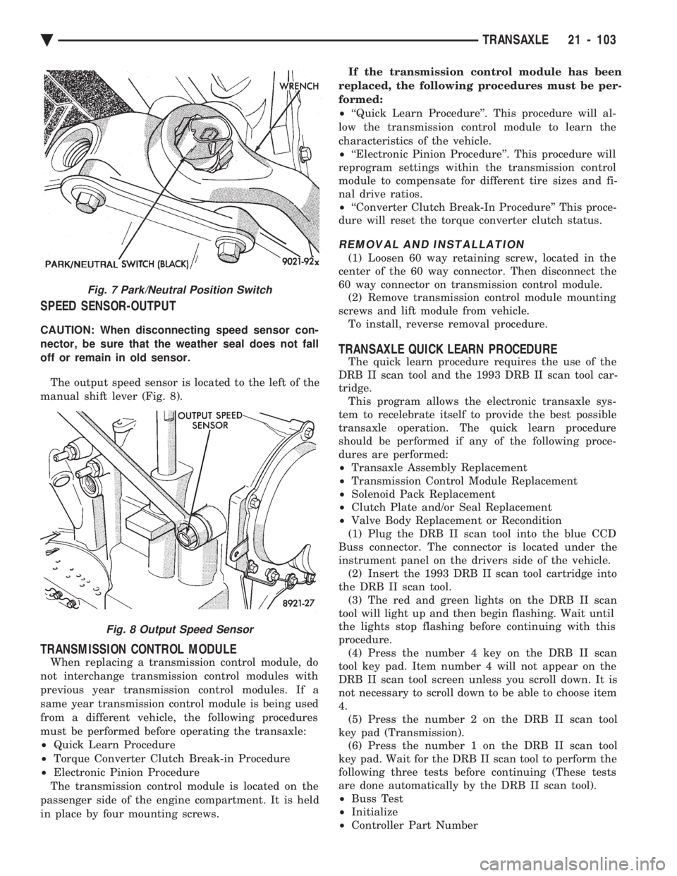
off or remain in old sensor. The output speed sensor is located to the left of the
manual shift lever (Fig. 8).
TRANSMISSION CONTROL MODULE
When replacing a transmission control module, do
not interchange transmission control modules with
previous year transmission control modules. If a
same year transmission control module is being used
from a different vehicle, the following procedures
must be performed before operating the transaxle:
² Quick Learn Procedure
² Torque Converter Clutch Break-in Procedure
² Electronic Pinion Procedure
The transmission control module is located on the
passenger side of the engine compartment. It is held
in place by four mounting screws. If the transmission control module has been
replaced, the following procedures must be per-
formed:
² ``Quick Learn Procedure''. This procedure will al-
low the transmission control module to learn the
characteristics of the vehicle.
² ``Electronic Pinion Procedure''. This procedure will
reprogram settings within the transmission control
module to compensate for different tire sizes and fi-
nal drive ratios.
² ``Converter Clutch Break-In Procedure'' This proce-
dure will reset the torque converter clutch status.
REMOVAL AND INSTALLATION
(1) Loosen 60 way retaining screw, located in the
center of the 60 way connector. Then disconnect the
60 way connector on transmission control module. (2) Remove transmission control module mounting
screws and lift module from vehicle. To install, reverse removal procedure.
TRANSAXLE QUICK LEARN PROCEDURE
The quick learn procedure requires the use of the
DRB II scan tool and the 1993 DRB II scan tool car-
tridge. This program allows the electronic transaxle sys-
tem to recelebrate itself to provide the best possible
transaxle operation. The quick learn procedure
should be performed if any of the following proce-
dures are performed:
² Transaxle Assembly Replacement
² Transmission Control Module Replacement
² Solenoid Pack Replacement
² Clutch Plate and/or Seal Replacement
² Valve Body Replacement or Recondition
(1) Plug the DRB II scan tool into the blue CCD
Buss connector. The connector is located under the
instrument panel on the drivers side of the vehicle. (2) Insert the 1993 DRB II scan tool cartridge into
the DRB II scan tool. (3) The red and green lights on the DRB II scan
tool will light up and then begin flashing. Wait until
the lights stop flashing before continuing with this
procedure. (4) Press the number 4 key on the DRB II scan
tool key pad. Item number 4 will not appear on the
DRB II scan tool screen unless you scroll down. It is
not necessary to scroll down to be able to choose item
4. (5) Press the number 2 on the DRB II scan tool
key pad (Transmission). (6) Press the number 1 on the DRB II scan tool
key pad. Wait for the DRB II scan tool to perform the
following three tests before continuing (These tests
are done automatically by the DRB II scan tool).
² Buss Test
² Initialize
² Controller Part Number
Fig. 7 Park/Neutral Position Switch
Fig. 8 Output Speed Sensor
Ä TRANSAXLE 21 - 103
Page 2169 of 2438
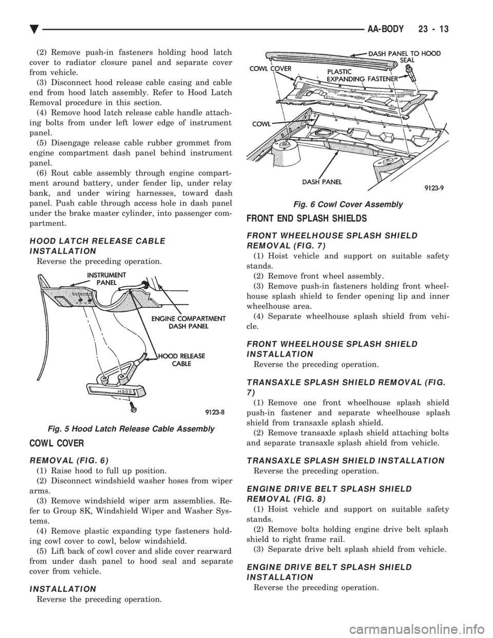
(2) Remove push-in fasteners holding hood latch
cover to radiator closure panel and separate cover
from vehicle. (3) Disconnect hood release cable casing and cable
end from hood latch assembly. Refer to Hood Latch
Removal procedure in this section. (4) Remove hood latch release cable handle attach-
ing bolts from under left lower edge of instrument
panel. (5) Disengage release cable rubber grommet from
engine compartment dash panel behind instrument
panel. (6) Rout cable assembly through engine compart-
ment around battery, under fender lip, under relay
bank, and under wiring harnesses, toward dash
panel. Push cable through access hole in dash panel
under the brake master cylinder, into passenger com-
partment.
HOOD LATCH RELEASE CABLE INSTALLATION
Reverse the preceding operation.
COWL COVER
REMOVAL (FIG. 6)
(1) Raise hood to full up position.
(2) Disconnect windshield washer hoses from wiper
arms. (3) Remove windshield wiper arm assemblies. Re-
fer to Group 8K, Windshield Wiper and Washer Sys-
tems. (4) Remove plastic expanding type fasteners hold-
ing cowl cover to cowl, below windshield. (5) Lift back of cowl cover and slide cover rearward
from under dash panel to hood seal and separate
cover from vehicle.
INSTALLATION
Reverse the preceding operation.
FRONT END SPLASH SHIELDS
FRONT WHEELHOUSE SPLASH SHIELD REMOVAL (FIG. 7)
(1) Hoist vehicle and support on suitable safety
stands. (2) Remove front wheel assembly.
(3) Remove push-in fasteners holding front wheel-
house splash shield to fender opening lip and inner
wheelhouse area. (4) Separate wheelhouse splash shield from vehi-
cle.
FRONT WHEELHOUSE SPLASH SHIELD INSTALLATION
Reverse the preceding operation.
TRANSAXLE SPLASH SHIELD REMOVAL (FIG.7)
(1) Remove one front wheelhouse splash shield
push-in fastener and separate wheelhouse splash
shield from transaxle splash shield. (2) Remove transaxle splash shield attaching bolts
and separate transaxle splash shield from vehicle.
TRANSAXLE SPLASH SHIELD INSTALLATION
Reverse the preceding operation.
ENGINE DRIVE BELT SPLASH SHIELD REMOVAL (FIG. 8)
(1) Hoist vehicle and support on suitable safety
stands. (2) Remove bolts holding engine drive belt splash
shield to right frame rail. (3) Separate drive belt splash shield from vehicle.
ENGINE DRIVE BELT SPLASH SHIELDINSTALLATION
Reverse the preceding operation.
Fig. 5 Hood Latch Release Cable Assembly
Fig. 6 Cowl Cover Assembly
Ä AA-BODY 23 - 13
Page 2185 of 2438
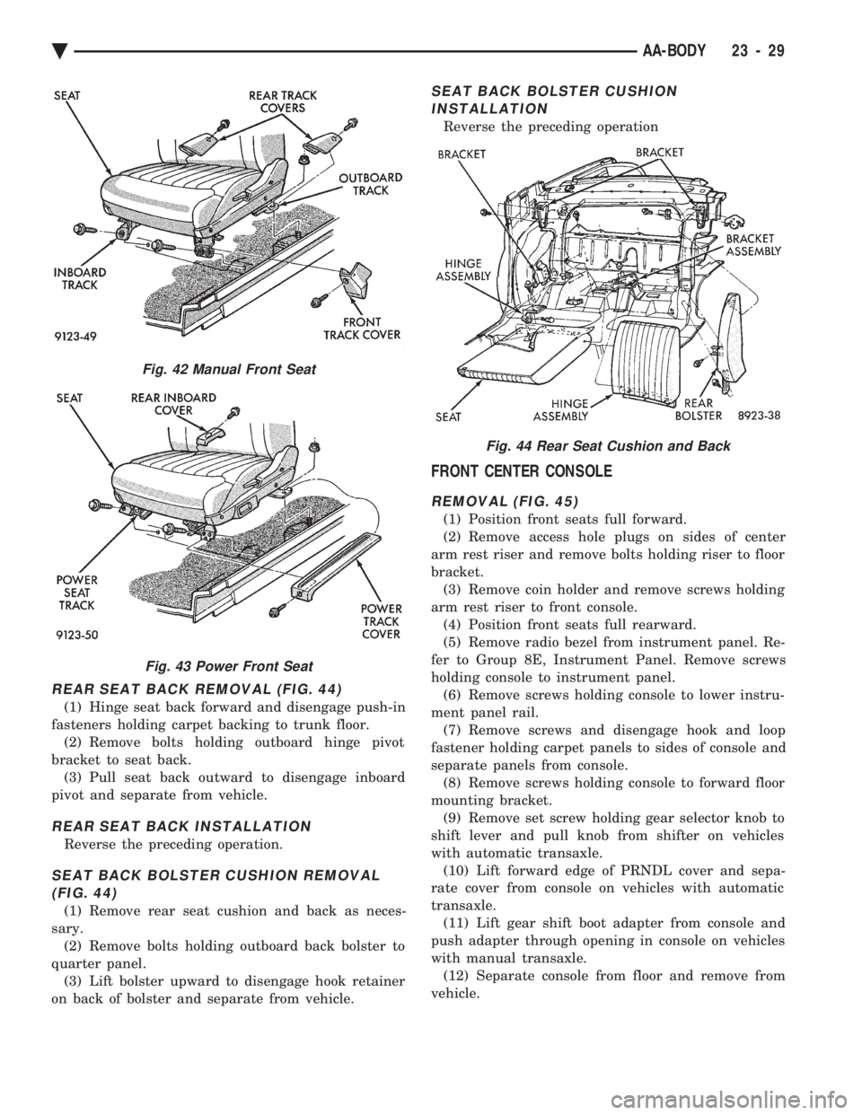
REAR SEAT BACK REMOVAL (FIG. 44)
(1) Hinge seat back forward and disengage push-in
fasteners holding carpet backing to trunk floor. (2) Remove bolts holding outboard hinge pivot
bracket to seat back. (3) Pull seat back outward to disengage inboard
pivot and separate from vehicle.
REAR SEAT BACK INSTALLATION
Reverse the preceding operation.
SEAT BACK BOLSTER CUSHION REMOVAL (FIG. 44)
(1) Remove rear seat cushion and back as neces-
sary. (2) Remove bolts holding outboard back bolster to
quarter panel. (3) Lift bolster upward to disengage hook retainer
on back of bolster and separate from vehicle.
SEAT BACK BOLSTER CUSHION INSTALLATION
Reverse the preceding operation
FRONT CENTER CONSOLE
REMOVAL (FIG. 45)
(1) Position front seats full forward.
(2) Remove access hole plugs on sides of center
arm rest riser and remove bolts holding riser to floor
bracket. (3) Remove coin holder and remove screws holding
arm rest riser to front console. (4) Position front seats full rearward.
(5) Remove radio bezel from instrument panel. Re-
fer to Group 8E, Instrument Panel. Remove screws
holding console to instrument panel. (6) Remove screws holding console to lower instru-
ment panel rail. (7) Remove screws and disengage hook and loop
fastener holding carpet panels to sides of console and
separate panels from console. (8) Remove screws holding console to forward floor
mounting bracket. (9) Remove set screw holding gear selector knob to
shift lever and pull knob from shifter on vehicles
with automatic transaxle. (10) Lift forward edge of PRNDL cover and sepa-
rate cover from console on vehicles with automatic
transaxle. (11) Lift gear shift boot adapter from console and
push adapter through opening in console on vehicles
with manual transaxle. (12) Separate console from floor and remove from
vehicle.
Fig. 42 Manual Front Seat
Fig. 43 Power Front Seat
Fig. 44 Rear Seat Cushion and Back
Ä AA-BODY 23 - 29
Page 2195 of 2438
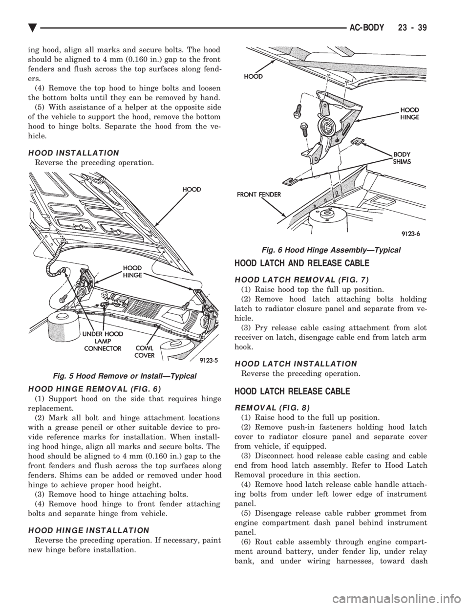
ing hood, align all marks and secure bolts. The hood
should be aligned to 4 mm (0.160 in.) gap to the front
fenders and flush across the top surfaces along fend-
ers.(4) Remove the top hood to hinge bolts and loosen
the bottom bolts until they can be removed by hand. (5) With assistance of a helper at the opposite side
of the vehicle to support the hood, remove the bottom
hood to hinge bolts. Separate the hood from the ve-
hicle.
HOOD INSTALLATION
Reverse the preceding operation.
HOOD HINGE REMOVAL (FIG. 6)
(1) Support hood on the side that requires hinge
replacement. (2) Mark all bolt and hinge attachment locations
with a grease pencil or other suitable device to pro-
vide reference marks for installation. When install-
ing hood hinge, align all marks and secure bolts. The
hood should be aligned to 4 mm (0.160 in.) gap to the
front fenders and flush across the top surfaces along
fenders. Shims can be added or removed under hood
hinge to achieve proper hood height. (3) Remove hood to hinge attaching bolts.
(4) Remove hood hinge to front fender attaching
bolts and separate hinge from vehicle.
HOOD HINGE INSTALLATION
Reverse the preceding operation. If necessary, paint
new hinge before installation.
HOOD LATCH AND RELEASE CABLE
HOOD LATCH REMOVAL (FIG. 7)
(1) Raise hood top the full up position.
(2) Remove hood latch attaching bolts holding
latch to radiator closure panel and separate from ve-
hicle. (3) Pry release cable casing attachment from slot
receiver on latch, disengage cable end from latch arm
hook.
HOOD LATCH INSTALLATION
Reverse the preceding operation.
HOOD LATCH RELEASE CABLE
REMOVAL (FIG. 8)
(1) Raise hood to the full up position.
(2) Remove push-in fasteners holding hood latch
cover to radiator closure panel and separate cover
from vehicle, if equipped. (3) Disconnect hood release cable casing and cable
end from hood latch assembly. Refer to Hood Latch
Removal procedure in this section. (4) Remove hood latch release cable handle attach-
ing bolts from under left lower edge of instrument
panel. (5) Disengage release cable rubber grommet from
engine compartment dash panel behind instrument
panel. (6) Rout cable assembly through engine compart-
ment around battery, under fender lip, under relay
bank, and under wiring harnesses, toward dash
Fig. 5 Hood Remove or InstallÐTypical
Fig. 6 Hood Hinge AssemblyÐTypical
Ä AC-BODY 23 - 39
Page 2210 of 2438
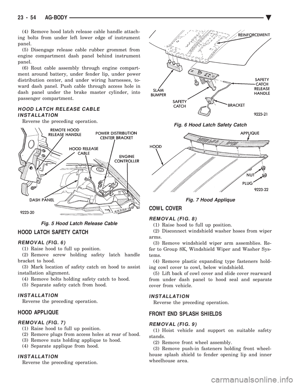
(4) Remove hood latch release cable handle attach-
ing bolts from under left lower edge of instrument
panel. (5) Disengage release cable rubber grommet from
engine compartment dash panel behind instrument
panel. (6) Rout cable assembly through engine compart-
ment around battery, under fender lip, under power
distribution center, and under wiring harnesses, to-
ward dash panel. Push cable through access hole in
dash panel under the brake master cylinder, into
passenger compartment.
HOOD LATCH RELEASE CABLE INSTALLATION
Reverse the preceding operation.
HOOD LATCH SAFETY CATCH
REMOVAL (FIG. 6)
(1) Raise hood to full up position.
(2) Remove screw holding safety latch handle
bracket to hood. (3) Mark location of safety catch on hood to assist
installation alignment. (4) Remove bolts holding safety catch to hood.
(5) Separate safety catch from hood.
INSTALLATION
Reverse the preceding operation.
HOOD APPLIQUE
REMOVAL (FIG. 7)
(1) Raise hood to full up position.
(2) Remove plugs from access holes at rear of hood.
(3) Remove nuts holding applique to hood.
(4) Separate applique from hood.
INSTALLATION
Reverse the preceding operation.
COWL COVER
REMOVAL (FIG. 8)
(1) Raise hood to full up position.
(2) Disconnect windshield washer hoses from wiper
arms. (3) Remove windshield wiper arm assemblies. Re-
fer to Group 8K, Windshield Wiper and Washer Sys-
tems. (4) Remove plastic expanding type fasteners hold-
ing cowl cover to cowl, below windshield. (5) Lift back of cowl cover and slide cover rearward
from under dash panel to hood seal and separate
cover from vehicle.
INSTALLATION
Reverse the preceding operation.
FRONT END SPLASH SHIELDS
REMOVAL (FIG. 9)
(1) Hoist vehicle and support on suitable safety
stands. (2) Remove front wheel assembly.
(3) Remove push-in fasteners holding front wheel-
house splash shield to fender opening lip and inner
wheelhouse area.
Fig. 5 Hood Latch Release Cable
Fig. 6 Hood Latch Safety Catch
Fig. 7 Hood Applique
23 - 54 AG-BODY Ä
Page 2220 of 2438
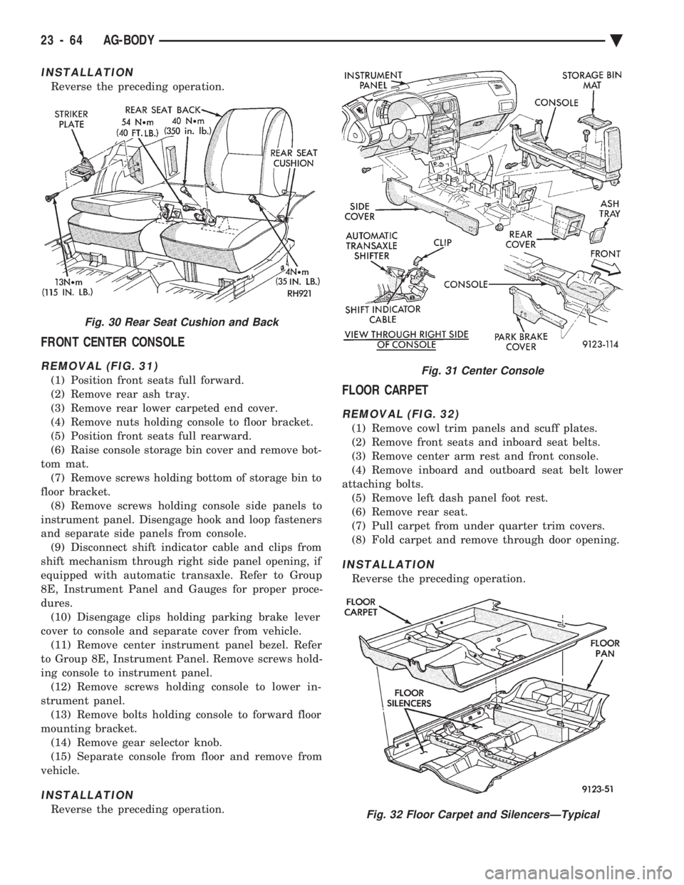
INSTALLATION
Reverse the preceding operation.
FRONT CENTER CONSOLE
REMOVAL (FIG. 31)
(1) Position front seats full forward.
(2) Remove rear ash tray.
(3) Remove rear lower carpeted end cover.
(4) Remove nuts holding console to floor bracket.
(5) Position front seats full rearward.
(6) Raise console storage bin cover and remove bot-
tom mat. (7) Remove screws holding bottom of storage bin to
floor bracket. (8) Remove screws holding console side panels to
instrument panel. Disengage hook and loop fasteners
and separate side panels from console. (9) Disconnect shift indicator cable and clips from
shift mechanism through right side panel opening, if
equipped with automatic transaxle. Refer to Group
8E, Instrument Panel and Gauges for proper proce-
dures. (10) Disengage clips holding parking brake lever
cover to console and separate cover from vehicle. (11) Remove center instrument panel bezel. Refer
to Group 8E, Instrument Panel. Remove screws hold-
ing console to instrument panel. (12) Remove screws holding console to lower in-
strument panel. (13) Remove bolts holding console to forward floor
mounting bracket. (14) Remove gear selector knob.
(15) Separate console from floor and remove from
vehicle.
INSTALLATION
Reverse the preceding operation.
FLOOR CARPET
REMOVAL (FIG. 32)
(1) Remove cowl trim panels and scuff plates.
(2) Remove front seats and inboard seat belts.
(3) Remove center arm rest and front console.
(4) Remove inboard and outboard seat belt lower
attaching bolts. (5) Remove left dash panel foot rest.
(6) Remove rear seat.
(7) Pull carpet from under quarter trim covers.
(8) Fold carpet and remove through door opening.
INSTALLATION
Reverse the preceding operation.
Fig. 30 Rear Seat Cushion and Back
Fig. 31 Center Console
Fig. 32 Floor Carpet and SilencersÐTypical
23 - 64 AG-BODY Ä
Page 2229 of 2438
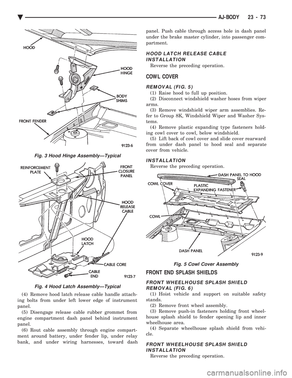
(4) Remove hood latch release cable handle attach-
ing bolts from under left lower edge of instrument
panel. (5) Disengage release cable rubber grommet from
engine compartment dash panel behind instrument
panel. (6) Rout cable assembly through engine compart-
ment around battery, under fender lip, under relay
bank, and under wiring harnesses, toward dash panel. Push cable through access hole in dash panel
under the brake master cylinder, into passenger com-
partment.
HOOD LATCH RELEASE CABLE INSTALLATION
Reverse the preceding operation.
COWL COVER
REMOVAL (FIG. 5)
(1) Raise hood to full up position.
(2) Disconnect windshield washer hoses from wiper
arms. (3) Remove windshield wiper arm assemblies. Re-
fer to Group 8K, Windshield Wiper and Washer Sys-
tems. (4) Remove plastic expanding type fasteners hold-
ing cowl cover to cowl, below windshield. (5) Lift back of cowl cover and slide cover rearward
from under dash panel to hood seal and separate
cover from vehicle.
INSTALLATION
Reverse the preceding operation.
FRONT END SPLASH SHIELDS
FRONT WHEELHOUSE SPLASH SHIELD REMOVAL (FIG. 6)
(1) Hoist vehicle and support on suitable safety
stands. (2) Remove front wheel assembly.
(3) Remove push-in fasteners holding front wheel-
house splash shield to fender opening lip and inner
wheelhouse area. (4) Separate wheelhouse splash shield from vehi-
cle.
FRONT WHEELHOUSE SPLASH SHIELD INSTALLATION
Reverse the preceding operation.
Fig. 3 Hood Hinge AssemblyÐTypical
Fig. 4 Hood Latch AssemblyÐTypical
Fig. 5 Cowl Cover Assembly
Ä AJ-BODY 23 - 73