1993 CHEVROLET PLYMOUTH ACCLAIM sunroof
[x] Cancel search: sunroofPage 31 of 2438
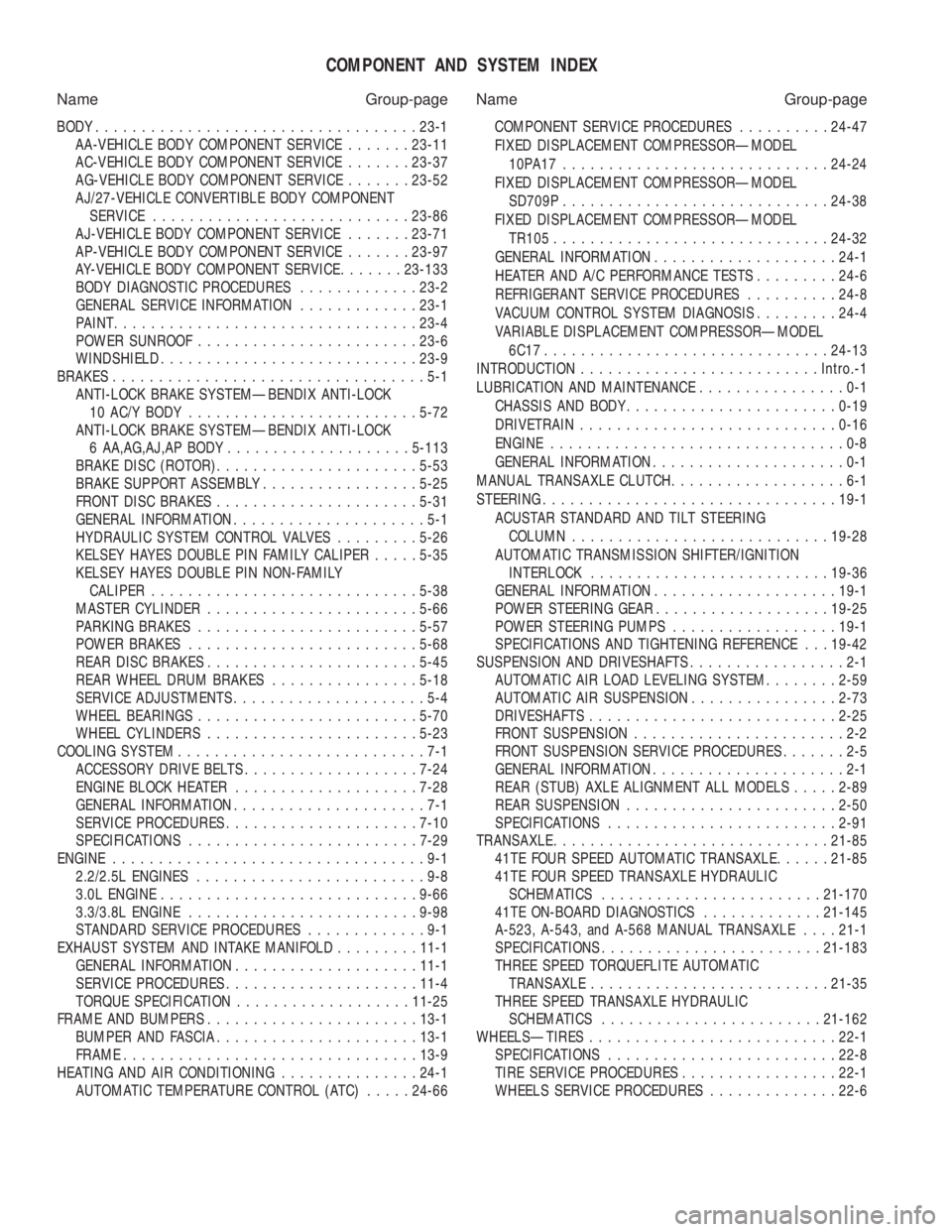
COMPONENT AND SYSTEM INDEX
Name Group-page Name Group-page
BODY ................................... 23-1
AA-VEHICLE BODY COMPONENT SERVICE .......23-11
AC-VEHICLE BODY COMPONENT SERVICE .......23-37
AG-VEHICLE BODY COMPONENT SERVICE .......23-52
AJ/27-VEHICLE CONVERTIBLE BODY COMPONENT SERVICE ............................ 23-86
AJ-VEHICLE BODY COMPONENT SERVICE .......23-71
AP-VEHICLE BODY COMPONENT SERVICE .......23-97
AY-VEHICLE BODY COMPONENT SERVICE .......23-133
BODY DIAGNOSTIC PROCEDURES .............23-2
GENERAL SERVICE INFORMATION .............23-1
PAINT ................................. 23-4
POWER SUNROOF ........................ 23-6
WINDSHIELD ............................ 23-9
BRAKES ..................................5-1
ANTI-LOCK BRAKE SYSTEMÐBENDIX ANTI-LOCK 10 AC/Y BODY ......................... 5-72
ANTI-LOCK BRAKE SYSTEMÐBENDIX ANTI-LOCK 6 AA,AG,AJ,AP BODY .................... 5-113
BRAKE DISC (ROTOR) ...................... 5-53
BRAKE SUPPORT ASSEMBLY .................5-25
FRONT DISC BRAKES ...................... 5-31
GENERAL INFORMATION .....................5-1
HYDRAULIC SYSTEM CONTROL VALVES .........5-26
KELSEY HAYES DOUBLE PIN FAMILY CALIPER .....5-35
KELSEY HAYES DOUBLE PIN NON-FAMILY CALIPER ............................. 5-38
MASTER CYLINDER ....................... 5-66
PARKING BRAKES ........................ 5-57
POWER BRAKES ......................... 5-68
REAR DISC BRAKES ....................... 5-45
REAR WHEEL DRUM BRAKES ................5-18
SERVICE ADJUSTMENTS .....................5-4
WHEEL BEARINGS ........................ 5-70
WHEEL CYLINDERS ....................... 5-23
COOLING SYSTEM ...........................7-1
ACCESSORY DRIVE BELTS ................... 7-24
ENGINE BLOCK HEATER .................... 7-28
GENERAL INFORMATION .....................7-1
SERVICE PROCEDURES ..................... 7-10
SPECIFICATIONS ......................... 7-29
ENGINE ..................................9-1
2.2/2.5L ENGINES .........................9-8
3.0L ENGINE ............................ 9-66
3.3/3.8L ENGINE ......................... 9-98
STANDARD SERVICE PROCEDURES .............9-1
EXHAUST SYSTEM AND INTAKE MANIFOLD .........11-1
GENERAL INFORMATION .................... 11-1
SERVICE PROCEDURES ..................... 11-4
TORQUE SPECIFICATION ................... 11-25
FRAME AND BUMPERS ....................... 13-1
BUMPER AND FASCIA ...................... 13-1
FRAME ................................ 13-9
HEATING AND AIR CONDITIONING ...............24-1
AUTOMATIC TEMPERATURE CONTROL (ATC) .....24-66 COMPONENT SERVICE PROCEDURES
..........24-47
FIXED DISPLACEMENT COMPRESSORÐMODEL 10PA17............................. 24-24
FIXED DISPLACEMENT COMPRESSORÐMODEL SD709P ............................. 24-38
FIXED DISPLACEMENT COMPRESSORÐMODEL TR105 .............................. 24-32
GENERAL INFORMATION .................... 24-1
HEATER AND A/C PERFORMANCE TESTS .........24-6
REFRIGERANT SERVICE PROCEDURES ..........24-8
VACUUM CONTROL SYSTEM DIAGNOSIS .........24-4
VARIABLE DISPLACEMENT COMPRESSORÐMODEL 6C17 ............................... 24-13
INTRODUCTION .......................... Intro.-1
LUBRICATION AND MAINTENANCE ................0-1
CHASSIS AND BODY ....................... 0-19
DRIVETRAIN ............................ 0-16
ENGINE ................................0-8
GENERAL INFORMATION .....................0-1
MANUAL TRANSAXLE CLUTCH ...................6-1
STEERING ................................ 19-1
ACUSTAR STANDARD AND TILT STEERING COLUMN ............................ 19-28
AUTOMATIC TRANSMISSION SHIFTER/IGNITION INTERLOCK .......................... 19-36
GENERAL INFORMATION .................... 19-1
POWER STEERING GEAR ................... 19-25
POWER STEERING PUMPS ..................19-1
SPECIFICATIONS AND TIGHTENING REFERENCE . . . 19-42
SUSPENSION AND DRIVESHAFTS .................2-1
AUTOMATIC AIR LOAD LEVELING SYSTEM ........2-59
AUTOMATIC AIR SUSPENSION ................2-73
DRIVESHAFTS ........................... 2-25
FRONT SUSPENSION .......................2-2
FRONT SUSPENSION SERVICE PROCEDURES .......2-5
GENERAL INFORMATION .....................2-1
REAR (STUB) AXLE ALIGNMENT ALL MODELS .....2-89
REAR SUSPENSION ....................... 2-50
SPECIFICATIONS ......................... 2-91
TRANSAXLE .............................. 21-85
41TE FOUR SPEED AUTOMATIC TRANSAXLE ......21-85
41TE FOUR SPEED TRANSAXLE HYDRAULIC SCHEMATICS ........................ 21-170
41TE ON-BOARD DIAGNOSTICS .............21-145
A-523, A-543, and A-568 MANUAL TRANSAXLE ....21-1
SPECIFICATIONS ........................ 21-183
THREE SPEED TORQUEFLITE AUTOMATIC TRANSAXLE .......................... 21-35
THREE SPEED TRANSAXLE HYDRAULIC SCHEMATICS ........................ 21-162
WHEELSÐTIRES ........................... 22-1
SPECIFICATIONS ......................... 22-8
TIRE SERVICE PROCEDURES .................22-1
WHEELS SERVICE PROCEDURES ..............22-6
Page 422 of 2438

COMPASS MODULE REPLACEMENT
(1) Remove overhead console.
(2) Using a small screwdriver, release the 2 snaps
at rear of compass module. (3) After releasing the 2 snaps, slide compass mod-
ule rearward until free of mounting bar. (4) For installation reverse above procedures.
AMBIENT TEMPERATURE SENSOR
(1) Raise and support vehicle on safety stands.
(2) From behind front bumper fascia, remove screw
attaching sensor to front lower crossmember (Fig. 7). (3) For installation, reverse above procedures.
AC AND AY BODY
INDEX
page page
Ambient Temperature Sensor ............... 12
Automatic Calibration Set Procedure ........... 8
Bezel/Button Switch Removal ............... 10
Bus Accessed Diagnostics .................. 10
Console Removal ........................ 10
Electronic Board Assembly Replacement ....... 10
Electronic Vehicle Information Center (EVIC) Overhead Console ....................... 6 Engine Compartment Node Removal
.......... 12
EVIC Self Check Diagnostics ................ 8
Manual Calibration Set Procedure ............. 8
Map Reading Lamps/Power Sunroof Switch Removal .............................. 11
Overhead Reading/Courtesy Lamp Console ..... 11
Wiring Harness Removal ................... 10
ELECTRONIC VEHICLE INFORMATION CENTER
(EVIC) OVERHEAD CONSOLE
The Electronic Vehicle Information Center is a
computer controlled warning system which, monitors
various sensors used on the vehicle. The system sup-
plements the warning indicators in 8the instrument
cluster. Visual warning messages are displayed by a
digital display in the overhead console (Fig. 1).
When a warning message has been activated, a
tone will sound to attract the driver's attention. The
warning message will then be displayed on the over-
head console until the condition is corrected or a new
display function is called up. A tone will announce each new warning condition.
For complete diagnostic procedures for the EVIC
systems, refer to the Body-Chassis Diagnostic Test
Procedures Manual. The EVIC has a 24 function system that provides
the driver with visual messages when a warning con-
dition exists. These messages are displayed on the
overhead console. For complete EVIC overhead console operating in-
structions, refer to the Owners Manual provided with
the vehicle.
EVIC BUTTON FUNCTIONS
TIME button will display:
² Time of day
² Day of week
² Day of month
² Month of year
The body controller is the source of this informa-
tion. The EVIC function buttons are used to reset
and display this data.
² To set HOURS, press TIME button and within four
seconds press the SET button. An arrow will appear
on the display and point to the hours. Press and hold
the SET button to advance the hours or INFO button
to set back the hours.
² To set MINUTES, press TIME button. The arrow
will point to the minutes. Press and hold the SET
button to advance the minutes or INFO button to set
back the minutes.
Fig. 7 Ambient Temperature Sensor
Fig. 1 EVIC Overhead Console
8C - 6 OVERHEAD CONSOLE Ä
Page 427 of 2438

MAP READING LAMPS/POWER SUNROOF SWITCH
REMOVAL
SWITCH REPLACEMENT
(1) Remove console, refer to Console Replacement.
(2) Disconnect switch wiring connector from re-
taining bracket. (3) Pry switch out of bezel snap tabs.
(4) Replace switch.
(5) For installation reverse above procedures.
LAMP/LENS REMOVAL
(1) Remove lens by inserting a flat blade tool into
slot located on the left side of lens. Pry lens to the
side and swing down as it unhooks from housing
(Fig. 4). (2) Replace lamp as necessary.
(3) Position lens with the center tabs on the left
side of lens snap into place. The lens are identified
with L and R on the reverse side. Do not reverse the
lens or it may damage the lens tabs.
POWER SUNROOF SWITCH/BEZEL REMOVAL
(1) Remove console, refer to Overhead Reading/
Courtesy Lamp Console Replacement. (2) Disconnect switch wiring connector from re-
taining bracket. (3) Pry switch out of bezel. Replace switch. If nec-
essary, push carefully at top closest to roof of bezel to
disengage trim bezel and pivot bezel out of housing. (4) Replace switch.
(5) For installation reverse above procedures.
OVERHEAD READING/COURTESY LAMP CONSOLE
The two reading/courtesy lamps are actuated by
pressing on the switch (Fig. 7):
² Courtesy lamps for when a door is opened
² Illuminated entry system is activated
² Headlamp switch is turned fully clockwise
The map lamp console also includes:
² A cubby storage bin. ²
Power sunroof switch, if equipped.
READING/COURTESY LAMP CONSOLE
REMOVAL
(1) Remove screws from visor tip-pin retainers.
(2) Slide console forward until free from retainer
bracket. (3) Disconnect wiring.
(4) For installation reverse above procedures. For
vehicles equipped with sunroof, avoid sliding console
to install. Install screws for console attachment and
push at rear of unit to snap over mounting bracket
for engagement.
LAMP/LENS REMOVAL
(1) Remove lens by inserting a flat blade tool be-
tween the round end of lamp lens and housing. Pry
lens from the housing. Pivot the lens and remove
(Fig. 7). (2) Replace lamp as necessary.
(3) Position lens into housing by locating lens
pivot and snap into place.
OVERHEAD CONSOLE WIRING HARNESS REMOVAL
(1) Remove console, refer to Overhead Reading/
Courtesy Lamp Console Removal. (2) Disconnect wiring connector from retaining
bracket. (3) Remove four screws attaching lamp housing to
console bezel. (4) Remove wiring and lamp housing.
(5) Remove lamp and replace assembly.
(6) For installation, reverse above procedures.
Fig. 6 EVIC Overhead Console Connector
Fig. 7 Reading/Courtesy Lamp Console
Ä OVERHEAD CONSOLE 8C - 11
Page 1067 of 2438
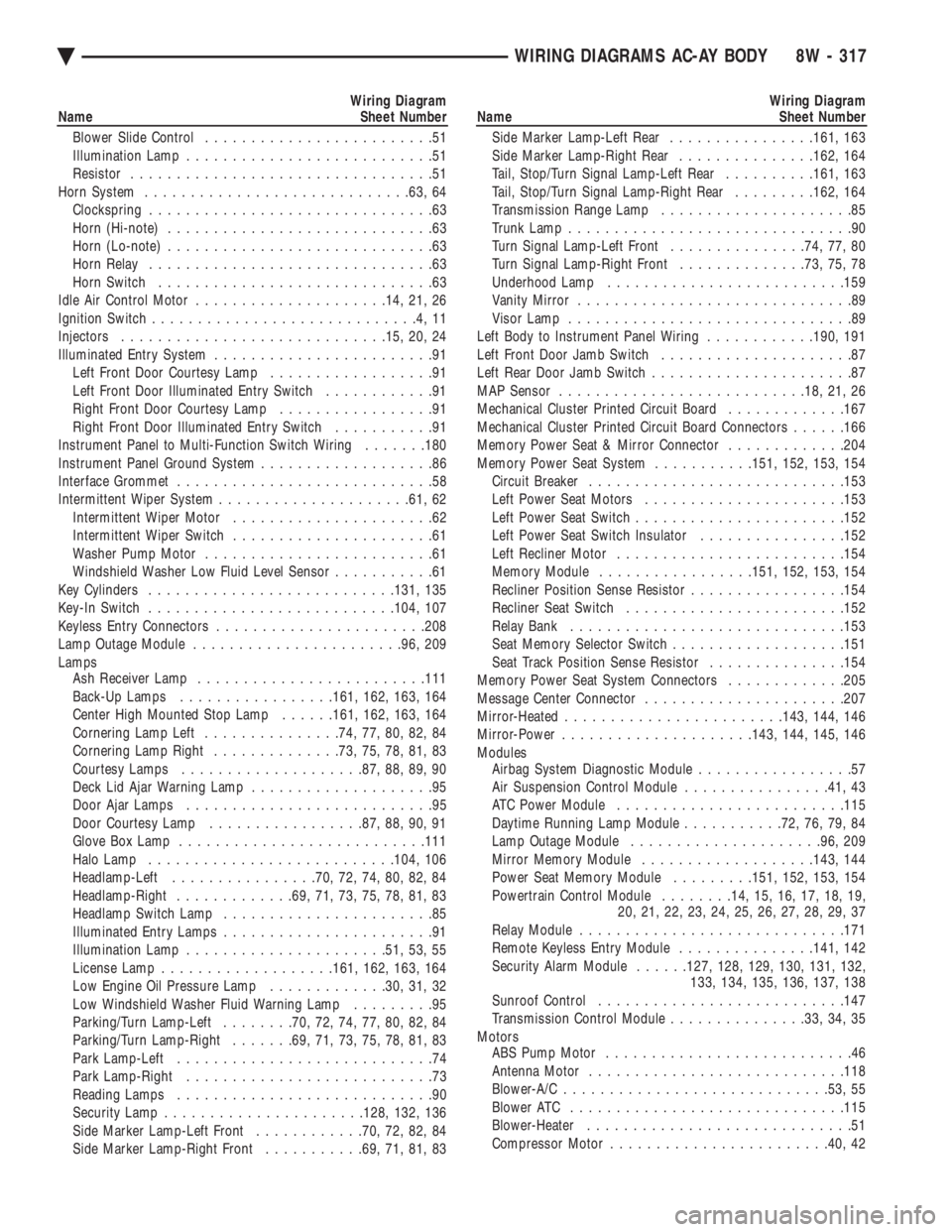
Wiring Diagram
Name Sheet Number
Blower Slide Control .........................51
Illumination Lamp ...........................51
Resistor .................................51
Horn System ............................ .63, 64
Clockspring ...............................63
Horn (Hi-note) .............................63
Horn (Lo-note) .............................63
Horn Relay ...............................63
Horn Switch ..............................63
Idle Air Control Motor .................... .14, 21, 26
Ignition Switch .............................4,11
Injectors ............................ .15, 20, 24
Illuminated Entry System ........................91
Left Front Door Courtesy Lamp ..................91
Left Front Door Illuminated Entry Switch ............91
Right Front Door Courtesy Lamp .................91
Right Front Door Illuminated Entry Switch ...........91
Instrument Panel to Multi-Function Switch Wiring .......180
Instrument Panel Ground System ...................86
Interface Grommet ............................58
Intermittent Wiper System .................... .61, 62
Intermittent Wiper Motor ......................62
Intermittent Wiper Switch ......................61
Washer Pump Motor .........................61
Windshield Washer Low Fluid Level Sensor ...........61
Key Cylinders .......................... .131, 135
Key-In Switch .......................... .104, 107
Keyless Entry Connectors ...................... .208
Lamp Outage Module ...................... .96, 209
Lamps Ash Receiver Lamp ........................ .111
Back-Up Lamps ................ .161, 162, 163, 164
Center High Mounted Stop Lamp ......161, 162, 163, 164
Cornering Lamp Left ...............74, 77, 80, 82, 84
Cornering Lamp Right ..............73, 75, 78, 81, 83
Courtesy Lamps ................... .87, 88, 89, 90
Deck Lid Ajar Warning Lamp ....................95
Door Ajar Lamps ...........................95
Door Courtesy Lamp ................ .87, 88, 90, 91
Glove Box Lamp .......................... .111
Halo Lamp .......................... .104, 106
Headlamp-Left ............... .70, 72, 74, 80, 82, 84
Headlamp-Right ............ .69, 71, 73, 75, 78, 81, 83
Headlamp Switch Lamp .......................85
Illuminated Entry Lamps .......................91
Illumination Lamp ..................... .51, 53, 55
License Lamp .................. .161, 162, 163, 164
Low Engine Oil Pressure Lamp .............30, 31, 32
Low Windshield Washer Fluid Warning Lamp .........95
Parking/Turn Lamp-Left ........70, 72, 74, 77, 80, 82, 84
Parking/Turn Lamp-Right .......69, 71, 73, 75, 78, 81, 83
Park Lamp-Left ............................74
Park Lamp-Right ...........................73
Reading Lamps ............................90
Security Lamp ..................... .128, 132, 136
Side Marker Lamp-Left Front ............70, 72, 82, 84
Side Marker Lamp-Right Front ...........69, 71, 81, 83Wiring Diagram
Name Sheet Number
Side Marker Lamp-Left Rear ................161, 163
Side Marker Lamp-Right Rear ...............162, 164
Tail, Stop/Turn Signal Lamp-Left Rear ..........161, 163
Tail, Stop/Turn Signal Lamp-Right Rear .........162, 164
Transmission Range Lamp .....................85
Trunk Lamp ...............................90
Turn Signal Lamp-Left Front ...............74, 77, 80
Turn Signal Lamp-Right Front ..............73, 75, 78
Underhood Lamp ......................... .159
Vanity Mirror ..............................89
Visor Lamp ...............................89
Left Body to Instrument Panel Wiring ............190, 191
Left Front Door Jamb Switch .....................87
Left Rear Door Jamb Switch ......................87
MAP Sensor .......................... .18, 21, 26
Mechanical Cluster Printed Circuit Board .............167
Mechanical Cluster Printed Circuit Board Connectors ......166
Memory Power Seat & Mirror Connector .............204
Memory Power Seat System ...........151, 152, 153, 154
Circuit Breaker ........................... .153
Left Power Seat Motors ..................... .153
Left Power Seat Switch ...................... .152
Left Power Seat Switch Insulator ................152
Left Recliner Motor ........................ .154
Memory Module ................ .151, 152, 153, 154
Recliner Position Sense Resistor .................154
Recliner Seat Switch ....................... .152
Relay Bank ............................. .153
Seat Memory Selector Switch ...................151
Seat Track Position Sense Resistor ...............154
Memory Power Seat System Connectors .............205
Message Center Connector ..................... .207
Mirror-Heated ....................... .143, 144, 146
Mirror-Power .................... .143, 144, 145, 146
Modules Airbag System Diagnostic Module .................57
Air Suspension Control Module ................41, 43
ATC Power Module ........................ .115
Daytime Running Lamp Module ...........72, 76, 79, 84
Lamp Outage Module .................... .96, 209
Mirror Memory Module .................. .143, 144
Power Seat Memory Module .........151, 152, 153, 154
Powertrain Control Module ........14, 15, 16, 17, 18, 19,
20, 21, 22, 23, 24, 25, 26, 27, 28, 29, 37
Relay Module ............................ .171
Remote Keyless Entry Module ...............141, 142
Security Alarm Module ......127, 128, 129, 130, 131, 132,
133, 134, 135, 136, 137, 138
Sunroof Control .......................... .147
Transmission Control Module ...............33, 34, 35
Motors ABS Pump Motor ...........................46
Antenna Motor ........................... .118
Blower-A/C ............................ .53, 55
Blower ATC ............................. .115
Blower-Heater .............................51
Compressor Motor ....................... .40, 42
Ä WIRING DIAGRAMS AC-AY BODY 8W - 317
Page 1068 of 2438
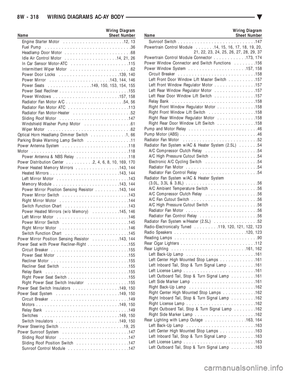
Wiring Diagram
Name Sheet Number
Engine Starter Motor ..................... .12, 13
Fuel Pump ...............................36
Headlamp Door Motor ........................68
Idle Air Control Motor .................. .14, 21, 26
In Car Sensor Motor-ATC .................... .115
Intermittent Wiper Motor ......................62
Power Door Locks ..................... .139, 140
Power Mirror ..................... .143, 144, 146
Power Seats ............... .149, 150, 153, 154, 155
Power Seat Recliner ........................ .155
Power Windows ....................... .157, 158
Radiator Fan Motor A/C .................... .54, 56
Radiator Fan Motor ATC ..................... .113
Radiator Fan Motor-Heater .....................52
Sliding Roof Motor ........................ .147
Windshield Washer Pump Motor .................61
Wiper Motor ..............................62
Optical Horn Headlamp Dimmer Switch .............1,66
Parking Brake Warning Lamp Switch ................11
Power Antenna System ....................... .118
Motor .................................. .118
Power Antenna & NBS Relay ...................118
Power Distribution Center ..........2,4,6,8,10, 169, 170
Power Heated Memory Mirrors ................143, 144
Heated Mirror s........................ .143, 144
Left Mirror Motor ......................... .143
Memory Module ....................... .143, 144
Power Mirror Position Sensing Resistor .........143, 144
Power Mirror Switch ....................... .143
Right Mirror Motor ........................ .144
Switch Function Chart ...................... .143
Power Heated Mirrors (w/o Memory) ..........145, 146
Left Mirror Motor ......................... .146
Power Mirror Switch ....................... .145
Right Mirror Motor ........................ .146
Switch Function Chart ...................... .145
Power Mirror Position Sensing Resistor ..........143, 144
Power Seat with Power Recliner-Right ...............155
Circuit Breaker ........................... .155
Power Seat Motor ......................... .155
Recliner Motor ........................... .155
Recliner Seat Switch ....................... .155
Relay Bank ............................. .155
Right Power Seat Switch ..................... .155
Right Power Seat Switch Insulator ...............155
Power Seat Switch Insulators .................149, 150
Power Seat System ...................... .149, 150
Circuit Breaker ........................... .149
Motors ............................. .149, 150
Relay Bank ............................. .149
Switches ........................... .149, 150
Switch Insulators ...................... .149, 150
Power Steering Switch ...................... .19, 25
Power Sunroof System ....................... .147
Sliding Roof Motor ........................ .147
Sliding Roof Position Switch ...................147
Sunroof Control Module ..................... .147Wiring Diagram
Name Sheet Number
Sunroof Switch ........................... .147
Powertrain Control Module .......14, 15, 16, 17, 18, 19, 20,
21, 22, 23, 24, 25, 26, 27, 28, 29, 37
Powertrain Control Module Connector ............173, 174
Power Window Connector and Switch Functions ........156
Power Window System .................... .157, 158
Circuit Breaker ........................... .158
Left Front Door Window Lift Master Switch ..........157
Left Front Window Regulator Motor ...............157
Left Rear Window Regulator Motor ...............157
Left Rear Door Window Lift Switch ...............157
Relay Bank ............................. .158
Right Front Window Regulator Motor ..............158
Right Front Window Lift Switch .................158
Right Rear Window Regulator Motor ..............158
Right Rear Door Window Lift Switch ..............158
Pump and Motor Relay .........................46
Pump Motor (ABS) ............................46
Radiator Fan Motor ...........................52
Radiator Fan System w/AC & Heater System (2.5L) .......54
A/C Compressor Clutch Relay ...................54
A/C High Pressure Cutout Switch .................54
Electronic A/C Cycling Switch ...................54
Radiator Fan Motor ..........................54
Radiator Fan Control Relay .....................54
Radiator Fan System w/AC & Heater System (3.0L, 3.3L & 3.8L) ..........................56
A/C Ambient Temperature Switch .................56
A/C Compressor Clutch Relay ...................56
A/C Fan Cutout Switch ........................56
A/C High Pressure Cutout Switch .................56
Radiator Fan Motor ..........................56
Radiator Fan Control Relay .....................56
Radiator Fan System w/Heater (2.5L) ................52
Radio-Electronically Tuned .........119, 120, 121, 122, 123
Radio Speakers ......................... .120, 123
Reading Lamps ..............................90
Rear Cigar Lighters .......................... .112
Rear Lighting .......................... .161, 162
Left Back-Up Lamp ........................ .161
Left Center High Mounted Stop Lamps .............161
Left Inboard Tail, Stop & Turn Signal Lamp ..........161
Left License Lamp ......................... .161
Left Outboard Tail, Stop & Turn Signal Lamp .........161
Left Side Marker Lamp ...................... .161
Right Back-Up Lamp ....................... .162
Right Center High Mounted Stop Lamps ............162
Right Inboard Tail, Stop & Turn Signal Lamp .........162
Right License Lamp ........................ .162
Right Outboard Tail, Stop & Turn Signal Lamp ........162
Right Side Marker Lamp ..................... .162
Rear Lighting with Lamp Outage ...............163, 164
Left Back-Up Lamp ........................ .163
Left Center High Mounted Stop Lamps .............163
Left Inboard Tail, Stop & Turn Signal Lamp ..........163
Left License Lamp ......................... .163
Left Outboard Tail, Stop & Turn Signal Lamp .........163
8W - 318 WIRING DIAGRAMS AC-AY BODY Ä
Page 1071 of 2438
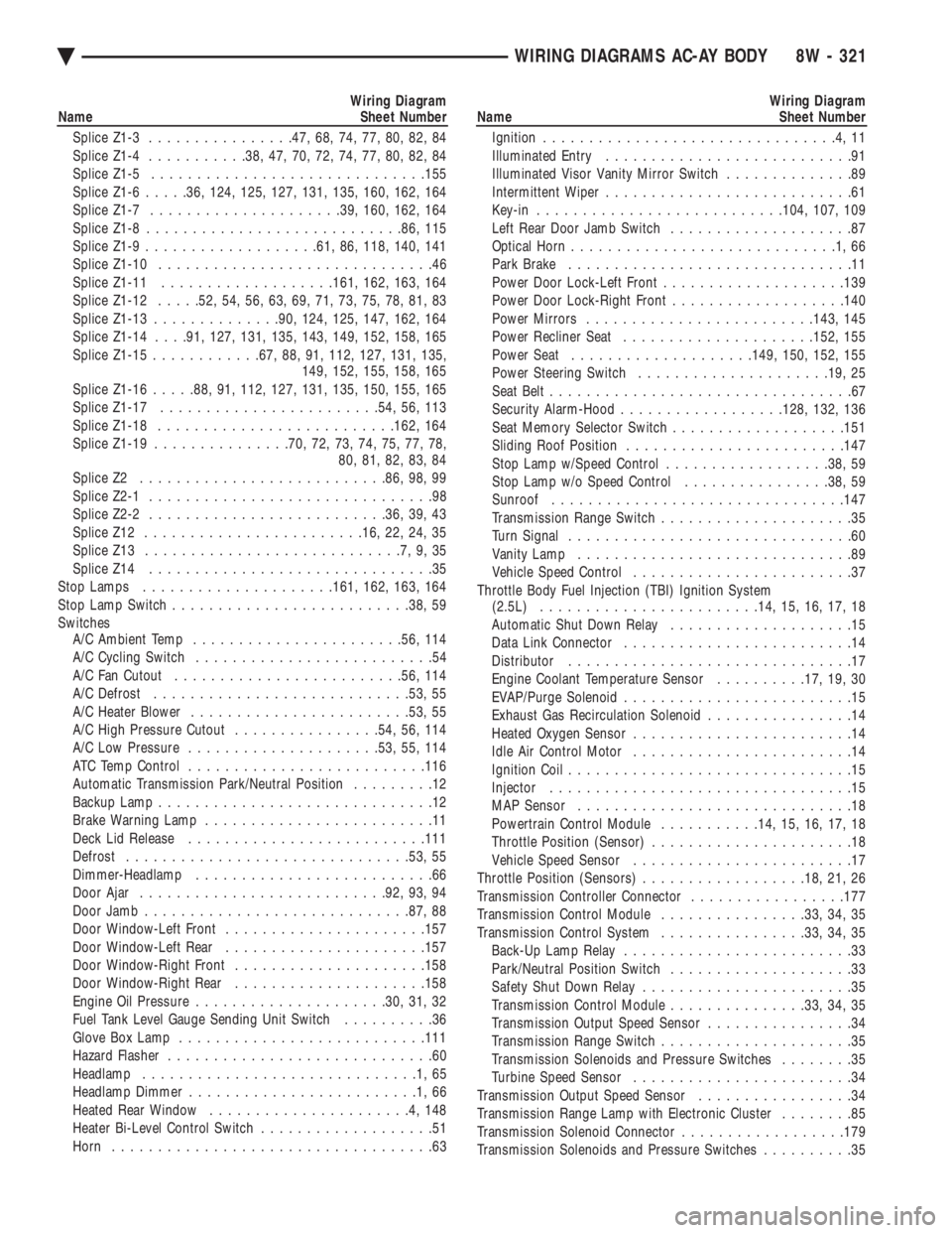
Wiring Diagram
Name Sheet Number
Splice Z1-3 ............... .47, 68, 74, 77, 80, 82, 84
Splice Z1-4 .......... .38, 47, 70, 72, 74, 77, 80, 82, 84
Splice Z1-5 ............................. .155
Splice Z1-6 .....36, 124, 125, 127, 131, 135, 160, 162, 164
Splice Z1-7 .................... .39, 160, 162, 164
Splice Z1-8 ........................... .86, 115
Splice Z1-9 .................. .61, 86, 118, 140, 141
Splice Z1-10 ..............................46
Splice Z1-11 .................. .161, 162, 163, 164
Splice Z1-12 .....52, 54, 56, 63, 69, 71, 73, 75, 78, 81, 83
Splice Z1-13 ............. .90, 124, 125, 147, 162, 164
Splice Z1-14 . . . .91, 127, 131, 135, 143, 149, 152, 158, 165
Splice Z1-15 ........... .67, 88, 91, 112, 127, 131, 135,
149, 152, 155, 158, 165
Splice Z1-16 .....88, 91, 112, 127, 131, 135, 150, 155, 165
Splice Z1-17 ....................... .54, 56, 113
Splice Z1-18 ......................... .162, 164
Splice Z1-19 .............. .70, 72, 73, 74, 75, 77, 78,
80, 81, 82, 83, 84
Splice Z2 .......................... .86, 98, 99
Splice Z2-1 ...............................98
Splice Z2-2 ......................... .36, 39, 43
Splice Z12 ....................... .16, 22, 24, 35
Splice Z13 ............................7,9,35
Splice Z14 ...............................35
Stop Lamps .................... .161, 162, 163, 164
Stop Lamp Switch ......................... .38, 59
Switches A/C Ambient Temp ...................... .56, 114
A/C Cycling Switch ..........................54
A/C Fan Cutout ........................ .56, 114
A/C Defrost ........................... .53, 55
A/C Heater Blower ....................... .53, 55
A/C High Pressure Cutout ................54, 56, 114
A/C Low Pressure .................... .53, 55, 114
ATC Temp Control ......................... .116
Automatic Transmission Park/Neutral Position .........12
Backup Lamp ..............................12
Brake Warning Lamp .........................11
Deck Lid Release ......................... .111
Defrost .............................. .53, 55
Dimmer-Headlamp ..........................66
Door Ajar .......................... .92, 93, 94
Door Jamb ............................ .87, 88
Door Window-Left Front ..................... .157
Door Window-Left Rear ..................... .157
Door Window-Right Front .................... .158
Door Window-Right Rear .................... .158
Engine Oil Pressure .................... .30, 31, 32
Fuel Tank Level Gauge Sending Unit Switch ..........36
Glove Box Lamp .......................... .111
Hazard Flasher .............................60
Headlamp ..............................1,65
Headlamp Dimmer .........................1,66
Heated Rear Window ......................4,148
Heater Bi-Level Control Switch ...................51
Horn ...................................63Wiring Diagram
Name Sheet Number
Ignition ................................4,11
Illuminated Entry ...........................91
Illuminated Visor Vanity Mirror Switch ..............89
Intermittent Wiper ...........................61
Key-in .......................... .104, 107, 109
Left Rear Door Jamb Switch ....................87
Optical Horn .............................1,66
Park Brake ...............................11
Power Door Lock-Left Front ................... .139
Power Door Lock-Right Front ...................140
Power Mirrors ........................ .143, 145
Power Recliner Seat .................... .152, 155
Power Seat ................... .149, 150, 152, 155
Power Steering Switch .................... .19, 25
Seat Belt .................................67
Security Alarm-Hood ................. .128, 132, 136
Seat Memory Selector Switch ...................151
Sliding Roof Position ....................... .147
Stop Lamp w/Speed Control ..................38, 59
Stop Lamp w/o Speed Control ................38, 59
Sunroof ............................... .147
Transmission Range Switch .....................35
Turn Signal ...............................60
Vanity Lamp ..............................89
Vehicle Speed Control ........................37
Throttle Body Fuel Injection (TBI) Ignition System (2.5L) ....................... .14, 15, 16, 17, 18
Automatic Shut Down Relay ....................15
Data Link Connector .........................14
Distributor ...............................17
Engine Coolant Temperature Sensor ..........17, 19, 30
EVAP/Purge Solenoid .........................15
Exhaust Gas Recirculation Solenoid ................14
Heated Oxygen Sensor ........................14
Idle Air Control Motor ........................14
Ignition Coil ...............................15
Injector .................................15
MAP Sensor ..............................18
Powertrain Control Module ...........14, 15, 16, 17, 18
Throttle Position (Sensor) ......................18
Vehicle Speed Sensor ........................17
Throttle Position (Sensors) ..................18, 21, 26
Transmission Controller Connector .................177
Transmission Control Module ................33, 34, 35
Transmission Control System ................33, 34, 35
Back-Up Lamp Relay .........................33
Park/Neutral Position Switch ....................33
Safety Shut Down Relay .......................35
Transmission Control Module ...............33, 34, 35
Transmission Output Speed Sensor ................34
Transmission Range Switch .....................35
Transmission Solenoids and Pressure Switches ........35
Turbine Speed Sensor ........................34
Transmission Output Speed Sensor .................34
Transmission Range Lamp with Electronic Cluster ........85
Transmission Solenoid Connector ..................179
Transmission Solenoids and Pressure Switches ..........35
Ä WIRING DIAGRAMS AC-AY BODY 8W - 321
Page 2157 of 2438
BODY
CONTENTS
page page
AA-VEHICLE BODY COMPONENT SERVICE . . . 11
AC-VEHICLE BODY COMPONENT SERVICE . . . 37
AG-VEHICLE BODY COMPONENT SERVICE . . . 52
AJ-VEHICLE BODY COMPONENT SERVICE . . . 71
AJ/27-VEHICLE CONVERTIBLE BODYCOMPONENT SERVICE ................. 86
AP-VEHICLE BODY COMPONENT SERVICE . . . 97
AP/17-VEHICLE CONVERTIBLE BODY COMPONENT SERVICE ................. 117 AY-VEHICLE BODY COMPONENT SERVICE . . 133
BODY DIAGNOSTIC PROCEDURES .......... 2
GENERAL SERVICE INFORMATION .......... 1
PAINT ................................. 4
POWER SUNROOF ....................... 6
WINDSHIELD ........................... 9
GENERAL SERVICE INFORMATION
VEHICLE IDENTIFICATION
Throughout this group, references to the Chrysler
Corporation vehicle family identification code is used
when describing a procedure that is unique to that
vehicle. Refer to Introduction Group of this manual for
detailed information on vehicle identification. If a
procedure is common to all vehicles covered in this
manual, no reference will be made to a vehicle family
code.
SAFETY PRECAUTIONS AND WARNINGS
WARNING: WHEN SERVICING A VEHICLE EQUIPPED
WITH AIRBAG RESTRAINT SYSTEM, REVIEW ALL
PRECAUTIONS IN GROUP 8M, RESTRAINT SYS-
TEMS. PERSONAL INJURY CAN RESULT. EYE PROTECTION SHOULD BE USED WHEN SER-
VICING GLASS COMPONENTS. PERSONAL INJURY
CAN RESULT. USE A BREATHING FILTER WHEN SPRAYING
PAINT OR SOLVENTS IN A CONFINED AREA. PER-
SONAL INJURY CAN RESULT. AVOID PROLONGED SKIN CONTACT WITH PETRO-
LEUM OR ALCOHOL BASED CLEANING SOLVENTS.
PERSONAL INJURY CAN RESULT. DO NOT VENTURE UNDER A HOISTED VEHICLE
THAT IS NOT PROPERLY SUPPORTED ON SAFETY
STANDS. PERSONAL INJURY CAN RESULT.
CAUTION: When holes must be drilled or punched in
a inner body panel, verify depth of space to the outer
body panel, electrical wiring, or other components.
Damage to vehicle can result. Do not use abrasive chemicals or compounds on
painted surfaces. Damage to finish can result. Do not use harsh alkaline based cleaning solvents
on painted or upholstered surfaces. Damage to finish
or color can result. Do not hammer or pound on plastic trim panel
attaching fasteners when servicing interior trim. Plas-
tic panel can break.
Chrysler Corporation uses many different types of
push-in fasteners to secure the interior and exterior
trim to the body . Most of these fasteners can be reused
to assemble the trim during various repair procedures.
At times a push-in fastener cannot be removed without
damaging the fastener or the component it is holding.
If it is not possible to remove a fastener without
damaging a component or body, cut or brake the
fastener and use a new one when installing the com-
ponent. Never pry or pound on a plastic or press-board
trim component. Using a suitable fork-type prying
device, pry the fastener from the retaining hole behind
the component being removed. When installing, verify
that fastener is aligned with the retaining hole, by
hand, push directly on or over the fastener until it
seats. Apply a low force pull to the panel to verify that
it is secure. When it is necessary to remove components to service
another, it should not be necessary to apply excessive
force or bend a component to remove it. Before damag-
ing a component to be reused, verify there is no hidden
fasteners or captured edges holding the component in.
Often a fastener is hidden by carpeting nap or trim
plugs.
Ä BODY 23 - 1
Page 2162 of 2438
POWER SUNROOF INDEX
page page
Adjustment Bracket ........................ 7
Drain Channel ............................ 7
Drive Cable Locators ....................... 7
Drive Cables ............................. 8
General Information ........................ 6
Glass Panel ............................. 7 Glass Vertical Height Adjustment
.............. 6
Guide Assembly .......................... 8
Motor and Drive Gears ..................... 7
Sunshade ............................... 8
Wind Deflector ........................... 6
GENERAL INFORMATION
All sunroofs are equipped with drain tubes that are
located in the A, B or C-pillars. The drain tubes
must be kept open to prevent water from entering
the passenger compartment.
LUBRICATION
(1) Lubricate cables with Lubriplate or equivalent
when cables are replaced. (2) Periodically clean dirt from guide rail covers.
DRAIN TUBES
² Inspect the drain holes, located in the trough
around the sunroof opening to verify they are clear.
Inspection should be performed at least once a year
or when problems are suspected. If drain hose or
tubes are plugged, use compressed air or blunt flexi-
ble wire to clear them. If tubes cannot be cleared,
they must be repaired.
² The lower ends of the rear drain tubes are located
in the rear quarter panel drop wells. To clear rear
drain tubes, use compressed air or blunt flexible wire
from the lower ends of the tubes.
GLASS VERTICAL HEIGHT ADJUSTMENT
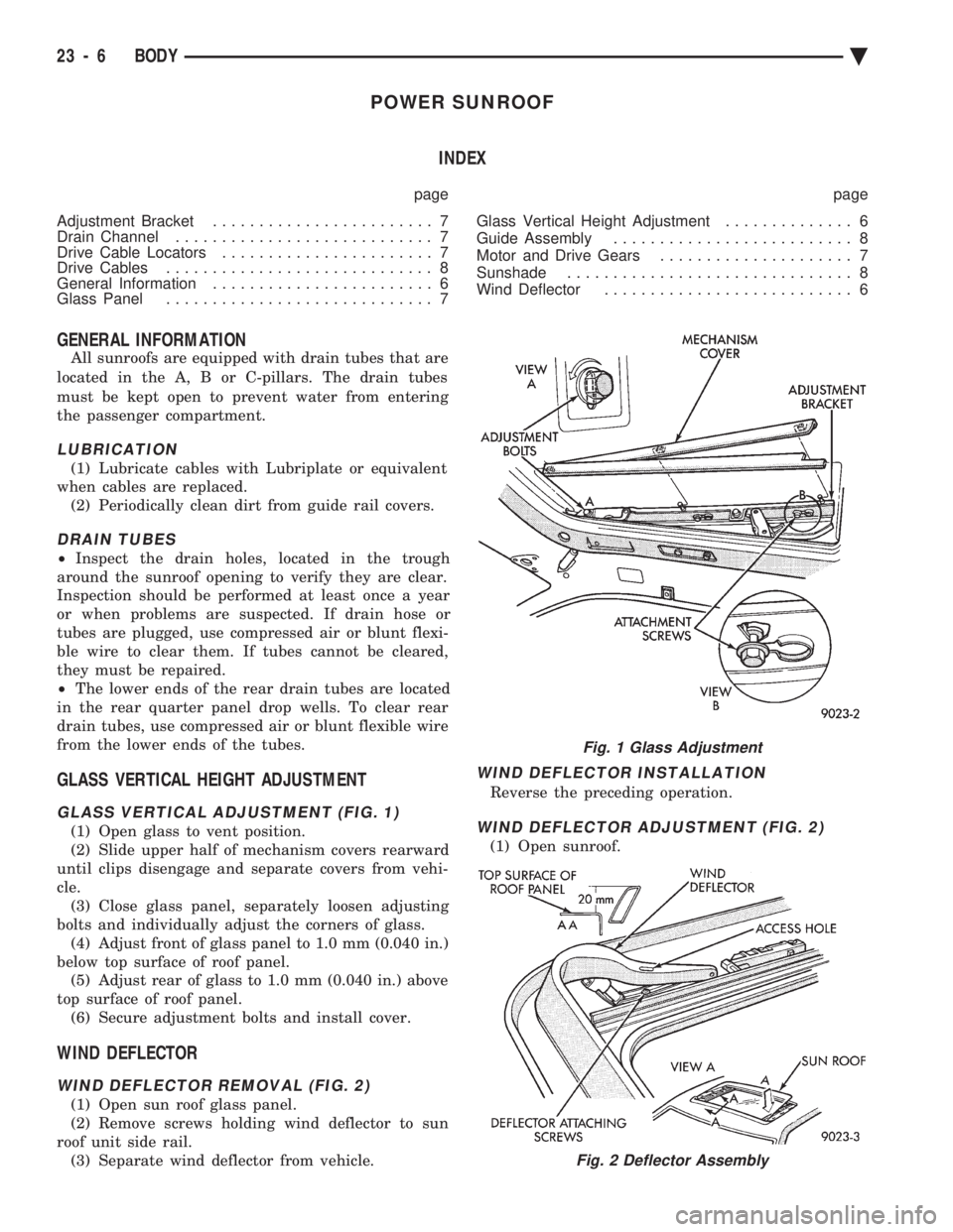
GLASS VERTICAL ADJUSTMENT (FIG. 1)
(1) Open glass to vent position.
(2) Slide upper half of mechanism covers rearward
until clips disengage and separate covers from vehi-
cle. (3) Close glass panel, separately loosen adjusting
bolts and individually adjust the corners of glass. (4) Adjust front of glass panel to 1.0 mm (0.040 in.)
below top surface of roof panel. (5) Adjust rear of glass to 1.0 mm (0.040 in.) above
top surface of roof panel. (6) Secure adjustment bolts and install cover.
WIND DEFLECTOR
WIND DEFLECTOR REMOVAL (FIG. 2)
(1) Open sun roof glass panel.
(2) Remove screws holding wind deflector to sun
roof unit side rail. (3) Separate wind deflector from vehicle.
WIND DEFLECTOR INSTALLATION
Reverse the preceding operation.
WIND DEFLECTOR ADJUSTMENT (FIG. 2)
(1) Open sunroof.
Fig. 1 Glass Adjustment
Fig. 2 Deflector Assembly
23 - 6 BODY Ä