1993 CHEVROLET PLYMOUTH ACCLAIM pc 194
[x] Cancel search: pc 194Page 680 of 2438

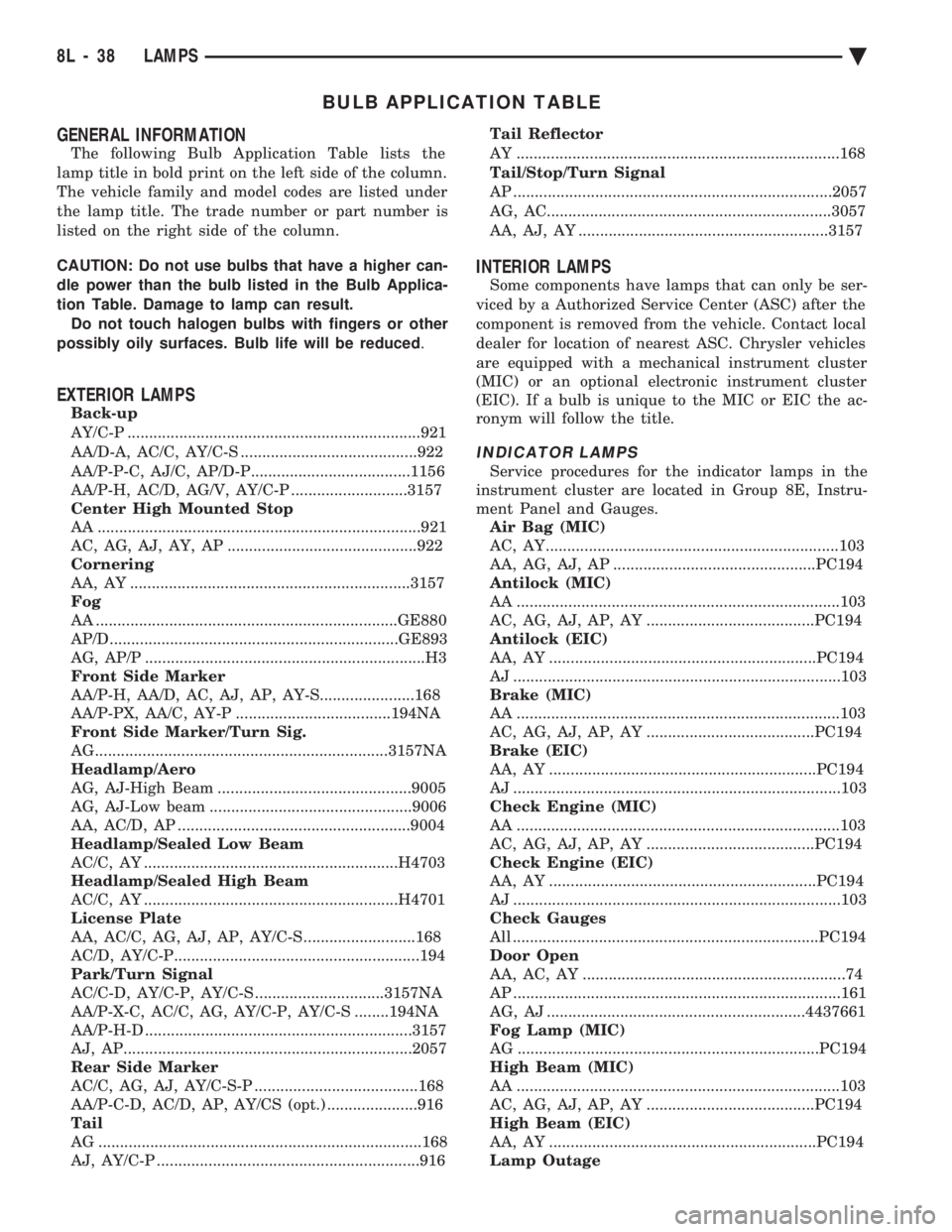
BULB APPLICATION TABLE
GENERAL INFORMATION
The following Bulb Application Table lists the
lamp title in bold print on the left side of the column.
The vehicle family and model codes are listed under
the lamp title. The trade number or part number is
listed on the right side of the column.
CAUTION: Do not use bulbs that have a higher can-
dle power than the bulb listed in the Bulb Applica-
tion Table. Damage to lamp can result. Do not touch halogen bulbs with fingers or other
possibly oily surfaces. Bulb life will be reduced .
EXTERIOR LAMPS
Back-up
AY/C-P ....................................................................921
AA/D-A, AC/C, AY/C-S .........................................922
AA/P-P-C, AJ/C, AP/D-P.....................................1156
AA/P-H, AC/D, AG/V, AY/C-P ...........................3157
Center High Mounted Stop
AA ...........................................................................921
AC, AG, AJ, AY, AP ............................................922
Cornering
AA, AY .................................................................3157
Fog
AA ......................................................................GE880
AP/D...................................................................GE893
AG, AP/P .................................................................H3
Front Side Marker
AA/P-H, AA/D, AC, AJ, AP, AY-S......................168
AA/P-PX, AA/C, AY-P ....................................194NA
Front Side Marker/Turn Sig.
AG....................................................................3157NA
Headlamp/Aero
AG, AJ-High Beam .............................................9005
AG, AJ-Low beam ...............................................9006
AA, AC/D, AP ......................................................9004
Headlamp/Sealed Low Beam
AC/C, AY ...........................................................H4703
Headlamp/Sealed High Beam
AC/C, AY ...........................................................H4701
License Plate
AA, AC/C, AG, AJ, AP, AY/C-S ..........................168
AC/D, AY/C-P.........................................................194
Park/Turn Signal
AC/C-D, AY/C-P, AY/C-S ..............................3157NA
AA/P-X-C, AC/C, AG, AY/C-P, AY/C-S ........194NA
AA/P-H-D ..............................................................3157
AJ, AP...................................................................2057
Rear Side Marker
AC/C, AG, AJ, AY/C-S-P ......................................168
AA/P-C-D, AC/D, AP, AY/CS (opt.) .....................916
Tail
AG ...........................................................................168
AJ, AY/C-P .............................................................916 Tail Reflector
AY ...........................................................................168
Tail/Stop/Turn Signal
AP ..........................................................................2057
AG, AC..................................................................3057
AA, AJ, AY ..........................................................3157
INTERIOR LAMPS
Some components have lamps that can only be ser-
viced by a Authorized Service Center (ASC) after the
component is removed from the vehicle. Contact local
dealer for location of nearest ASC. Chrysler vehicles
are equipped with a mechanical instrument cluster
(MIC) or an optional electronic instrument cluster
(EIC). If a bulb is unique to the MIC or EIC the ac-
ronym will follow the title.
INDICATOR LAMPS
Service procedures for the indicator lamps in the
instrument cluster are located in Group 8E, Instru-
ment Panel and Gauges. Air Bag (MIC)
AC, AY....................................................................103
AA, AG, AJ, AP ...............................................PC194
Antilock (MIC)
AA ...........................................................................103
AC, AG, AJ, AP, AY .......................................PC194
Antilock (EIC)
AA, AY ..............................................................PC194
AJ ............................................................................103
Brake (MIC)
AA ...........................................................................103
AC, AG, AJ, AP, AY .......................................PC194
Brake (EIC)
AA, AY ..............................................................PC194
AJ ............................................................................103
Check Engine (MIC)
AA ...........................................................................103
AC, AG, AJ, AP, AY .......................................PC194
Check Engine (EIC)
AA, AY ..............................................................PC194
AJ ............................................................................103
Check Gauges
All .......................................................................PC194
Door Open
AA, AC, AY .............................................................74
AP ............................................................................161
AG, AJ ............................................................4437661
Fog Lamp (MIC)
AG ......................................................................PC194
High Beam (MIC)
AA ...........................................................................103
AC, AG, AJ, AP, AY .......................................PC194
High Beam (EIC)
AA, AY ..............................................................PC194
Lamp Outage
8L - 38 LAMPS Ä
Page 681 of 2438

AA .............................................................................74
Low Fuel
AA ...........................................................................103
AP ............................................................................161
AC, AY...............................................................PC194
AG, AJ ............................................................5269245
Low Washer Fluid
AA, AC, AY .............................................................74
AP ............................................................................161
AG, AJ ............................................................4437661
Oil Pressure
All .......................................................................PC194
Trunk Open
AA, AC, AY .............................................................74
AP ............................................................................161
AG, AJ ............................................................4437661
Theft Alarm Set
AC, AY....................................................................168
AG, AJ ............................................................4437661
Turn Signal (MIC)
AA ...........................................................................103
AC, AG, AJ, AP, AY .......................................PC194
Turn Signal (EIC)
AA, AY ..............................................................PC194
Seat Belt (MIC)
AA ...........................................................................103
AC, AG, AJ, AP, AY .......................................PC194
Seat Belt (EIC)
AA, AY ..............................................................PC194
AJ ............................................................................103
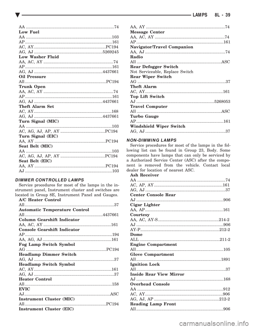
DIMMER CONTROLLED LAMPS
Service procedures for most of the lamps in the in-
strument panel, Instrument cluster and switches are
located in Group 8E, Instrument Panel and Gauges. A/C Heater Control
All ..............................................................................37
Automatic Temperature Control
All ....................................................................4437661
Column Gearshift Indicator
AA, AC, AY ...........................................................161
Console Gearshift Indicator
AP ............................................................................194
AA, AG, AJ ............................................................161
Fog Lamp Switch Symbol
AG ......................................................................PC194
Headlamp Dimmer Switch
AG, AJ ......................................................................37
Headlamp Switch Symbol
AC, AY....................................................................161
AG, AJ ......................................................................37
Heater Control
All ............................................................................158
EVIC
AJ...........................................................................ASC
Instrument Cluster (MIC)
All .......................................................................PC194
Instrument Cluster (EIC) AA, AY .....................................................................74
Message Center
AA, AC, AY .............................................................74
AP ............................................................................161
Navigator/Travel Companion
AA, AJ ......................................................................74
Radio
All ..........................................................................ASC
Rear Defogger Switch
Not Serviceable, Replace Switch
Rear Wiper Switch
AG .............................................................................37
Theft Alarm
AC, AY....................................................................161
Top Lift Switch
AJ ....................................................................5268053
Travel Computer
All ..........................................................................ASC
Turbo Gauge
AP ............................................................................161
Windshield Wiper Switch
AG, AJ ......................................................................37
NON-DIMMING LAMPS
Service procedures for most of the lamps in the fol-
lowing list can be found in Group 23, Body. Some
components have lamps that can only be serviced by
a Authorized Service Center (ASC) after the compo-
nent is removed from the vehicle. Contact local
dealer for location of nearest ASC. Ash Receiver
AA .............................................................................74
AC, AP, AY ............................................................161
AG, AJ ......................................................................37
Center Console Rear
AJ ............................................................................906
Cigar Lighter
AA, AP ....................................................................161
Courtesy
AA, AC, AY-S .....................................................214-2
AJ ............................................................................906
AY-P.....................................................................212-2
Dome
ALL ......................................................................211-2
Engine Compartment
All ............................................................................105
Glove Compartment
All ..........................................................................1891
Ignition Lock
All ..............................................................................37
Inside Rear View Mirror
AJ ............................................................................168
Overhead Console
AA ...........................................................................912
AC, AY....................................................................906
AG, AJ, AP .........................................................212-2
Reading Lamp Front
All ............................................................................906
Ä LAMPS 8L - 39
Page 745 of 2438

CHIME WARNING/REMINDER SYSTEM
CONTENTS
page page
BODY CONTROLLER REPLACEMENT ........ 5
CHIME MODULE REPLACEMENT AA and AP BODIES .............................. 5
CHIME SYSTEM DIAGNOSISÐAA AND AP BODIES .............................. 2
CHIME SYSTEM DIAGNOSISÐAC, AG, AJ AND AY BODIES ....................... 3
CHIME WARNING/REMINDER SYSTEM TEST . 1 GENERAL INFORMATION
.................. 1
HEADLAMP SWITCH REPLACEMENT ........ 5
KEY-IN SWITCH REPLACEMENT ............ 5
SEAT BELT BUCKLE REPLACEMENT ........ 5
SEAT BELT BUCKLE SWITCH TEST BUZZER SYSTEM .............................. 1
SERVICE PROCEDURES ................... 5
TIMED BUZZER-RELAY TESTÐAP BODY ..... 1
GENERAL INFORMATION
WARNING: ON VEHICLES EQUIPPED WITH AN AIR
BAG REFER TO THE AIR BAG PORTION OF THIS
SECTION FOR STEERING WHEEL OR SWITCH RE-
MOVAL AND INSTALLATION PROCEDURES.
BUZZER SYSTEM
The seat belt warning system uses both visual and
audible signals. A combined seat belt and key warn-
ing buzzer with a red light on the instrument panel. The system will always illuminate the seat belt
warning lamp for four to eight seconds when the ig-
nition switch is turned to the ON position. Also, only
if the driver does not fasten his seat belt, the buzzer
will sound during the same time interval. Passenger
belts are not connected to the system. A timed buzzer-relay is used to operate the system
for the time period. It consists of a time delay mech-
anism and buzzer assembly. Only the driver's seat
belt buckle has a switch that is connected to the sys-
tem.
CHIME WARNING/REMINDER SYSTEM
The chime warning/reminder system is similar in
operation to the buzzer system except for a more
pleasant sounding tone. This chime type tone sounds
for all three warning/reminder conditions; namely
headlamps left on, keys left in ignition and fasten
seat belt.
TIMED BUZZER-RELAY TESTÐAP BODY
PREPARATION
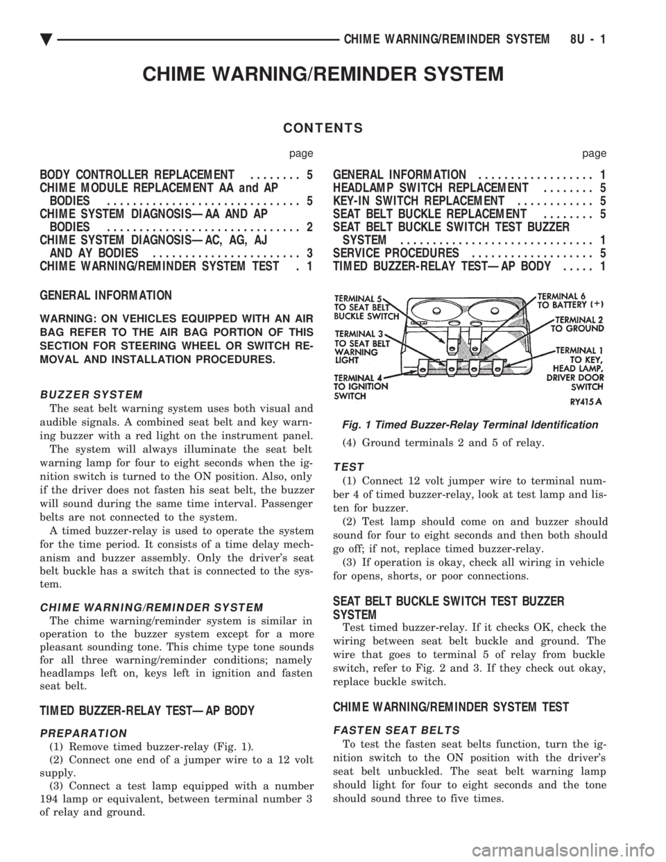
(1) Remove timed buzzer-relay (Fig. 1).
(2) Connect one end of a jumper wire to a 12 volt
supply. (3) Connect a test lamp equipped with a number
194 lamp or equivalent, between terminal number 3
of relay and ground. (4) Ground terminals 2 and 5 of relay.
TEST
(1) Connect 12 volt jumper wire to terminal num-
ber 4 of timed buzzer-relay, look at test lamp and lis-
ten for buzzer. (2) Test lamp should come on and buzzer should
sound for four to eight seconds and then both should
go off; if not, replace timed buzzer-relay. (3) If operation is okay, check all wiring in vehicle
for opens, shorts, or poor connections.
SEAT BELT BUCKLE SWITCH TEST BUZZER
SYSTEM
Test timed buzzer-relay. If it checks OK, check the
wiring between seat belt buckle and ground. The
wire that goes to terminal 5 of relay from buckle
switch, refer to Fig. 2 and 3. If they check out okay,
replace buckle switch.
CHIME WARNING/REMINDER SYSTEM TEST
FASTEN SEAT BELTS
To test the fasten seat belts function, turn the ig-
nition switch to the ON position with the driver's
seat belt unbuckled. The seat belt warning lamp
should light for four to eight seconds and the tone
should sound three to five times.
Fig. 1 Timed Buzzer-Relay Terminal Identification
Ä CHIME WARNING/REMINDER SYSTEM 8U - 1
Page 1063 of 2438

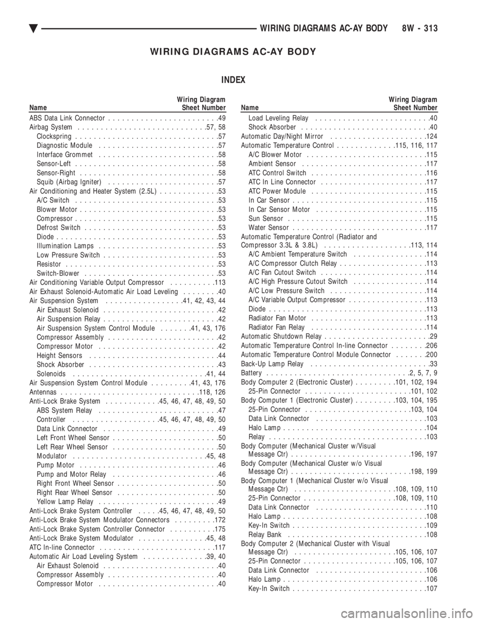
WIRING DIAGRAMS AC-AY BODY INDEX
Wiring Diagram
Name Sheet Number
ABS Data Link Connector ........................49
Airbag System ........................... .57, 58
Clockspring ...............................57
Diagnostic Module ..........................57
Interface Grommet ..........................58
Sensor-Left ...............................58
Sensor-Right ..............................58
Squib (Airbag Igniter) ........................57
Air Conditioning and Heater System (2.5L) .............53
A/C Switch ...............................53
Blower Motor ..............................53
Compressor ...............................53
Defrost Switch .............................53
Diode ...................................53
Illumination Lamps ..........................53
Low Pressure Switch .........................53
Resistor .................................53
Switch-Blower .............................53
Air Conditioning Variable Output Compressor ..........113
Air Exhaust Solenoid-Automatic Air Load Leveling ........40
Air Suspension System .................41, 42, 43, 44
Air Exhaust Solenoid .........................42
Air Suspension Relay .........................42
Air Suspension System Control Module .......41, 43, 176
Compressor Assembly ........................42
Compressor Motor ..........................42
Height Sensors ............................44
Shock Absorber ............................43
Solenoids ............................ .41, 44
Air Suspension System Control Module .........41, 43, 176
Antennas ............................. .118, 126
Anti-Lock Brake System ............45, 46, 47, 48, 49, 50
ABS System Relay ..........................47
Controller .................. .45, 46, 47, 48, 49, 50
Data Link Connector .........................49
Left Front Wheel Sensor .......................50
Left Rear Wheel Sensor .......................50
Modulator ............................ .45, 48
Pump Motor ..............................46
Pump and Motor Relay .......................46
Right Front Wheel Sensor ......................50
Right Rear Wheel Sensor ......................50
Yellow Lamp Relay ..........................49
Anti-Lock Brake System Controller .....45, 46, 47, 48, 49, 50
Anti-Lock Brake System Modulator Connectors .........172
Anti-Lock Brake System Controller Connector ..........175
Anti-Lock Brake System Modulator ...............45, 48
ATC In-line Connector ........................ .117
Automatic Air Load Leveling System ..............39, 40
Air Exhaust Solenoid .........................40
Compressor Assembly ........................40
Compressor Motor ..........................40Wiring Diagram
Name Sheet Number
Load Leveling Relay .........................40
Shock Absorber ............................40
Automatic Day/Night Mirror .................... .124
Automatic Temperature Control .............115, 116, 117
A/C Blower Motor ......................... .115
Ambient Sensor .......................... .117
ATC Control Switch ........................ .116
ATC In Line Connector ...................... .117
ATC Power Module ........................ .115
In Car Senso r............................ .115
In Car Sensor Motor ....................... .115
Sun Sensor ............................. .115
Water Sensor ............................ .117
Automatic Temperature Control (Radiator and
Compressor 3.3L & 3.8L) .................. .113, 114
A/C Ambient Temperature Switch ................114
A/C Compressor Clutch Relay ...................113
A/C Fan Cutout Switch ...................... .114
A/C High Pressure Cutout Switch ................114
A/C Low Pressure Switch .................... .114
A/C Variable Output Compressor .................113
Diode ................................. .113
Radiator Fan Motor ........................ .113
Radiator Fan Relay ........................ .114
Automatic Shutdown Relay .......................29
Automatic Temperature Control In-line Connector ........206
Automatic Temperature Control Module Connector .......200
Back-Up Lamp Relay ..........................33
Battery ...............................2,5,7,9
Body Computer 2 (Electronic Cluster) .........101, 102, 194
25-Pin Connector ...................... .101, 102
Body Computer 1 (Electronic Cluster) .........103, 104, 195
25-Pin Connector ...................... .103, 104
Data Link Connector ....................... .103
Halo Lamp .............................. .104
Relay ................................. .103
Body Computer (Mechanical Cluster w/Visual Message Ctr) ......................... .196, 197
Body Computer (Mechanical Cluster w/o Visual Message Ctr) ......................... .198, 199
Body Computer 1 (Mechanical Cluster w/o Visual Message Ctr) ..................... .108, 109, 110
25-Pin Connector ................... .108, 109, 110
Data Link Connector ....................... .110
Halo Lamp .............................. .108
Key-In Switch ............................ .109
Relay Bank ............................. .108
Body Computer 2 (Mechanical Cluster with Visual Message Ctr) ..................... .105, 106, 107
25-Pin Connector ................... .105, 106, 107
Data Link Connector ....................... .106
Halo Lamp .............................. .106
Key-In Switch ............................ .107
Ä WIRING DIAGRAMS AC-AY BODY 8W - 313