1993 CHEVROLET PLYMOUTH ACCLAIM roof rack
[x] Cancel search: roof rackPage 2221 of 2438
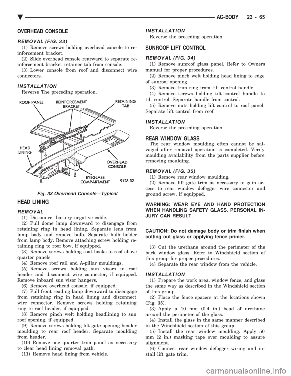
OVERHEAD CONSOLE
REMOVAL (FIG. 33)
(1) Remove screws holding overhead console to re-
inforcement bracket. (2) Slide overhead console rearward to separate re-
inforcement bracket retainer tab from console. (3) Lower console from roof and disconnect wire
connectors.
INSTALLATION
Reverse The preceding operation.
HEAD LINING
REMOVAL
(1) Disconnect battery negative cable.
(2) Pull dome lamp downward to disengage from
retaining ring in head lining. Separate lens from
lamp body and remove bulb. Separate bulb holder
from lamp body. Remove attaching screw holding re-
taining ring to roof bow, if equipped. (3) Remove screws holding coat hooks to roof above
quarter panels. (4) Remove roof rail and A-pillar mouldings.
(5) Remove screws holding sun visors to roof
header and disconnect wire connector, if equipped.
Remove inboard sun visor hangers. (6) Remove overhead console, if equipped.
(7) Pull front reading lamp downward to disengage
from retaining ring in head lining and disconnect
wire connector. Remove screws holding retaining
ring to roof header, if equipped. (8) Remove pinch welt holding headlining to sun
roof opening, if equipped. (9) Remove screws holding lift gate opening header
moulding to rear roof header. Separate moulding
from header. (10) Remove one quarter trim panel as necessary
to clear head lining removal path. (11) Remove head lining from vehicle.
INSTALLATION
Reverse the preceding operation.
SUNROOF LIFT CONTROL
REMOVAL (FIG. 34)
(1) Remove sunroof glass panel. Refer to Owners
manual for proper procedures. (2) Remove pinch welt holding head lining to edge
of sunroof opening. (3) Remove trim ring from tilt control handle.
(4) Remove screws holding tilt control handle to
tilt control. Separate handle from control. (5) Remove nuts holding lift control to roof panel.
Separate lift control from roof.
INSTALLATION
Reverse the preceding operation.
REAR WINDOW GLASS
The rear window moulding often cannot be sal-
vaged after removal operation is completed. Verify
moulding availability from the parts supplier before
removing moulding.
REMOVAL (FIG. 35)
(1) Remove rear window moulding.
(2) Remove lift gate trim as necessary to gain ac-
cess to rear window defogger wire connector and
ground screw, if equipped.
WARNING: WEAR EYE AND HAND PROTECTION
WHEN HANDLING SAFETY GLASS. PERSONAL IN-
JURY CAN RESULT.
CAUTION: Do not damage body or trim finish when
cutting out glass or applying fence primer.
(3) Cut the urethane around the perimeter of the
back window glass. Refer to Windshield section of
this group for proper procedures. (4) Separate the rear window from the vehicle.
INSTALLATION
(1) Prepare the work area, window fence, and glass
the same way as described in the Windshield section
of this group. (2) Place the fence spacers at the locations shown
(Fig. 35). (3) Apply a 10 mm (0.4 in.) bead of urethane
around the perimeter of the glass. (4) Install the glass in the same manner described
in the Windshield section of this group. (5) Install the rear window moulding. Apply 50
mm (2 in.) masking tape over moulding to assure
alignment. (6) Connect rear window defogger wiring and in-
stall lift gate trim.
Fig. 33 Overhead ConsoleÐTypical
Ä AG-BODY 23 - 65
Page 2227 of 2438
AJ-VEHICLE BODY COMPONENT SERVICE INDEX
page page
A-Pillar and Roof Rail Mouldings ............. 77
Cowl Cover ............................. 73
Cowl Panel Trim and Scuff Plates ............ 77
Door Glass ............................. 76
Door Glass Lift Plate and Guide Post ......... 76
Door Latch ............................. 75
Door Trim Panel ......................... 74
Floor Carpet ............................ 80
Front Center Console ..................... 79
Front Door and Hinge ..................... 75
Front Door Silencer and Water Shield ......... 74
Front End Splash Shields .................. 73
Front Seat Belts ......................... 78
Front Seats ............................. 78
Fuel Fill Door ........................... 84
Glass Run WeatherstripÐAJ-21 Body ......... 76
Grille .................................. 71
Grille Header Molding ..................... 71
Grille Opening Panel ...................... 71
Head Lining ............................. 81
Hood and Hinges ........................ 72
Hood Latch and Release Cable .............. 72
Inside Latch Release Handle ................ 76 Lower Grille
............................. 71
Outside Door Latch Release Handle .......... 76
Overhead Console ........................ 80
Power Door Lock Actuator .................. 76
Quarter Extension Trim Panel ............... 77
Quarter Glass Module ..................... 85
Quarter Trim Panel ....................... 77
Rear Seat Belts .......................... 78
Rear Seats ............................. 79
Rear Shelf Trim Panel ..................... 78
Rear Window Glass ...................... 81
Sun Roof Air Deflector .................... 81
Sun Roof Drain Tubes .................... 81
Sun Roof Weatherstrip .................... 81
Trunk Lid .............................. 82
Trunk Lid and Fuel Fill Door Release Cables . . . 83
Trunk Lid Hinge ......................... 82
Trunk Lid Latch .......................... 83
Trunk Lid Lock .......................... 83
Trunk Lid Luggage Rack ................... 83
Trunk Lid Torsion Bar ..................... 83
Trunk Opening Weatherstrip ................ 83
Window Regulator ........................ 75
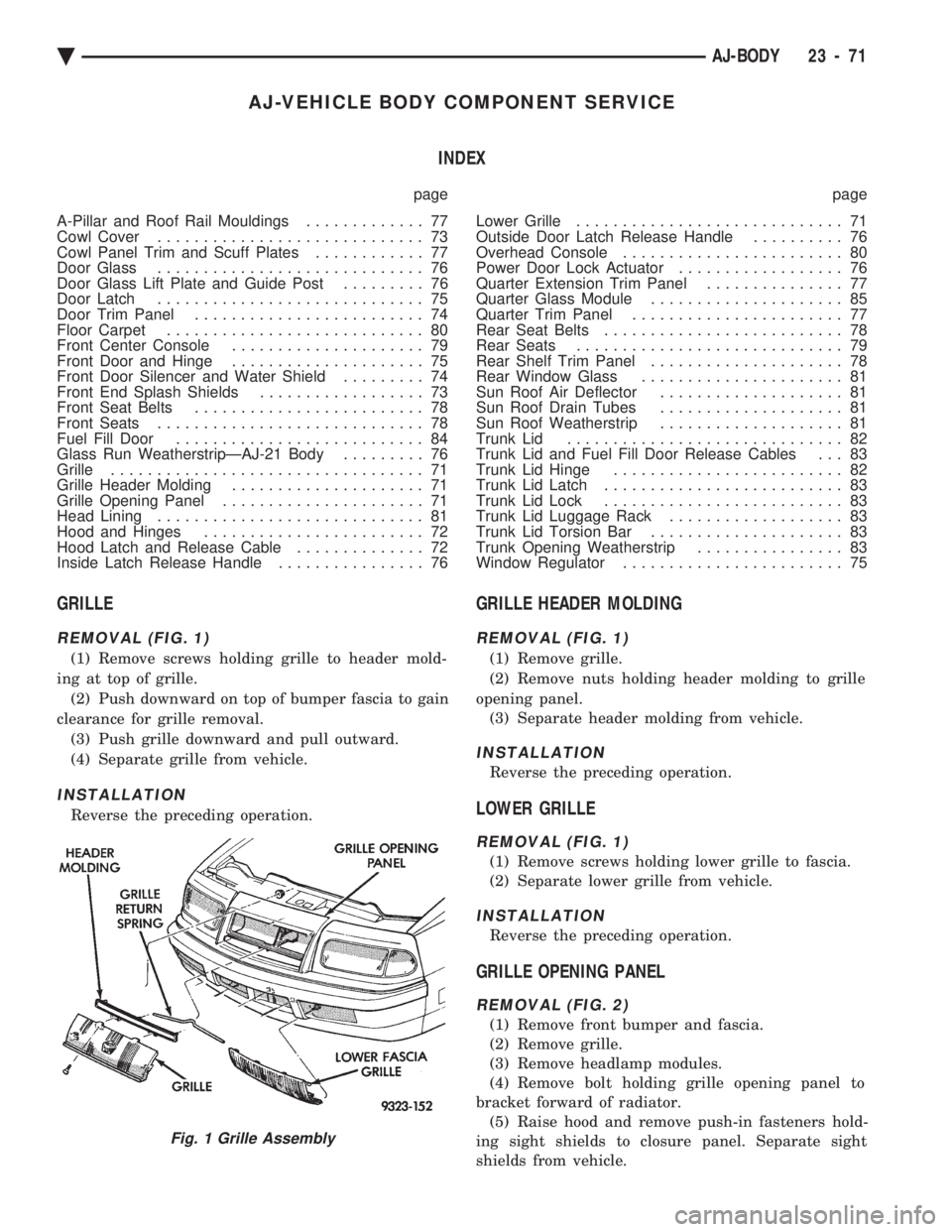
GRILLE
REMOVAL (FIG. 1)
(1) Remove screws holding grille to header mold-
ing at top of grille. (2) Push downward on top of bumper fascia to gain
clearance for grille removal. (3) Push grille downward and pull outward.
(4) Separate grille from vehicle.
INSTALLATION
Reverse the preceding operation.
GRILLE HEADER MOLDING
REMOVAL (FIG. 1)
(1) Remove grille.
(2) Remove nuts holding header molding to grille
opening panel. (3) Separate header molding from vehicle.
INSTALLATION
Reverse the preceding operation.
LOWER GRILLE
REMOVAL (FIG. 1)
(1) Remove screws holding lower grille to fascia.
(2) Separate lower grille from vehicle.
INSTALLATION
Reverse the preceding operation.
GRILLE OPENING PANEL
REMOVAL (FIG. 2)
(1) Remove front bumper and fascia.
(2) Remove grille.
(3) Remove headlamp modules.
(4) Remove bolt holding grille opening panel to
bracket forward of radiator. (5) Raise hood and remove push-in fasteners hold-
ing sight shields to closure panel. Separate sight
shields from vehicle.
Fig. 1 Grille Assembly
Ä AJ-BODY 23 - 71
Page 2236 of 2438
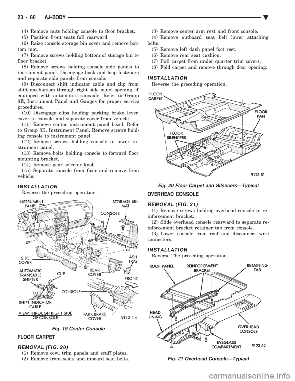
(4) Remove nuts holding console to floor bracket.
(5) Position front seats full rearward.
(6) Raise console storage bin cover and remove bot-
tom mat. (7) Remove screws holding bottom of storage bin to
floor bracket. (8) Remove screws holding console side panels to
instrument panel. Disengage hook and loop fasteners
and separate side panels from console. (9) Disconnect shift indicator cable and clip from
shift mechanism through right side panel opening, if
equipped with automatic transaxle. Refer to Group
8E, Instrument Panel and Gauges for proper service
procedures. (10) Disengage clips holding parking brake lever
cover to console and separate cover from vehicle. (11) Remove center instrument panel bezel. Refer
to Group 8E, Instrument Panel. Remove screws hold-
ing console to instrument panel. (12) Remove screws holding console to lower in-
strument panel. (13) Remove bolts holding console to forward floor
mounting bracket. (14) Remove gear selector knob.
(15) Separate console from floor and remove from
vehicle.
INSTALLATION
Reverse the preceding operation.
FLOOR CARPET
REMOVAL (FIG. 20)
(1) Remove cowl trim panels and scuff plates.
(2) Remove front seats and inboard seat belts. (3) Remove center arm rest and front console.
(4) Remove outboard seat belt lower attaching
bolts. (5) Remove left dash panel foot rest.
(6) Remove rear seat cushion.
(7) Pull carpet from under quarter trim covers.
(8) Fold carpet and remove through door opening.
INSTALLATION
Reverse the preceding operation.
OVERHEAD CONSOLE
REMOVAL (FIG. 21)
(1) Remove screws holding overhead console to re-
inforcement bracket. (2) Slide overhead console rearward to separate re-
inforcement bracket retainer tab from console. (3) Lower console from roof and disconnect wire
connectors.
INSTALLATION
Reverse The preceding operation.
Fig. 19 Center Console
Fig. 20 Floor Carpet and SilencersÐTypical
Fig. 21 Overhead ConsoleÐTypical
23 - 80 AJ-BODY Ä
Page 2243 of 2438
QUARTER WINDOW
REMOVAL
(1) Disengage snaps holding sling well to rear deck
panel. (2) From each side of vehicle, Disengage clips hold-
ing sling well to belt reinforcement brace. Drape
sling well over rear seat back into passenger com-
partment. (3) Remove screw holding quarter trim panel and
door weatherstrip to door opening. (4) Remove the cowl trim and scuff plate covers.
(5) Remove the rear seat cushion.
(6) Disconnect rear speaker wire connectors.
(7) Remove screws holding seat back to floor
brackets and rear shoulder belt retractors (Fig. 1).
Separate rear seat back from vehicle. (8) Remove screws holding quarter trim to quarter
panel at the boot latches. (9) Remove screws holding quarter trim to floor
pan kick up. (10) Separate quarter trim from rear reinforce-
ment. Position trim panel out of quarter window re-
moval path (Fig. 3). (11) Raise quarter window approximately 100 mm
(4 in.) from the down position. (12) Remove bolt holding glass stabilizer bumper
to top of quarter panel opening. (13) Disconnect power window motor wire connec-
tor. (14) Remove bolts holding quarter window assem-
bly to quarter panel and lift the assembly through
the opening at the top of the quarter panel.
INSTALLATION
Reverse the preceding operation. Align the quarter
glass to have adequate pressure on the weatherstrips
for proper sealing. Insert sling well drain tubes into
the holes in the floor pan.
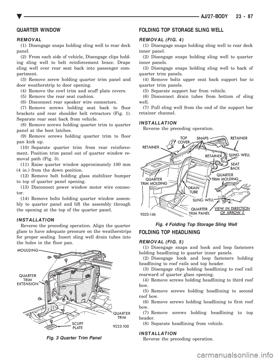
FOLDING TOP STORAGE SLING WELL
REMOVAL (FIG. 4)
(1) Disengage snaps holding sling well to rear deck
inner panel. (2) Disengage snaps holding sling well to quarter
inner panels. (3) Disengage snaps holding sling well to back of
quarter trim panels. (4) Remove bolts upper seat back support bar to
quarter trim panels. (5) Separate support bar from vehicle.
(6) Disconnect drain tubes from bottom of sling
well. (7) Pull sling well from the end of the support bar
retainer channel.
INSTALLATION
Reverse the preceding operation.
FOLDING TOP HEADLINING
REMOVAL (FIG. 5)
(1) Disengage snaps and hook and loop fasteners
holding headlining to quarter inner panels. (2) Disengage hook and loop fasteners holding
headlining to roof rails and top header. (3) Disengage clips holding headlining to roof rail
rearward of quarter glass opening. (4) Remove screws holding headlining to third roof
bow. (5) Remove screws holding headlining to second
roof bow. (6) Remove screws holding headlining to first roof
bow. (7) Remove screws holding headlining to top
header. (8) Separate headlining from vehicle.
INSTALLATION
Reverse the preceding operation.Fig. 3 Quarter Trim Panel
Fig. 4 Folding Top Storage Sling Well
Ä AJ/27-BODY 23 - 87
Page 2253 of 2438
AP-VEHICLE BODY COMPONENT SERVICE INDEX
page page
A-Pillar and Roof Rail Mouldings ............ 109
B-Pillar Trim PanelÐAP-44 Body ............ 109
Body Side Moulding and Applique ........... 108
Cowl Panel Trim and Scuff Plates ........... 109
Door Opening Weatherstrips ............... 107
Floor Carpet ........................... 113
Front Center Console .................... 113
Front Door and Hinge .................... 100
Front Door Belt Moulding and Weatherstrip .... 102
Front Door Glass ........................ 101
Front Door Glass Channel and Run Weatherstrip .......................... 103
Front Door Glass Run Lower Channels ....... 103
Front Door Latch ........................ 101
Front Door Side View Mirror ............... 101
Front Door Trim PanelÐAP-24/44 Body ....... 99
Front Door Water Shield .................. 100
Front Door Window Regulator/Manual ........ 103
Front Door Window Regulator/Power ......... 104
Front End Splash Shields .................. 99
Front Power Door Lock Actuator ............ 102
Front Seat BeltsÐAP-24 Body .............. 110
Front Seat BeltsÐAP-44 Body .............. 110
Front Seats ............................ 111
Grille .................................. 97
Grille Opening Panel ...................... 97
Head Lining ............................ 114
Hood and Hinges ........................ 97 Hood Latch and Release Cable
.............. 98
Lift Gate Luggage Rack ................... 116
Lift Gate Remote Release Cable ............ 115
Lower Quarter Trim PanelÐAP-44 Body ...... 109
Outside Front Door Latch Release Handle ..... 101
Outside Rear Door Latch Release Handle ..... 105
Overhead Console ....................... 113
Quarter Glass Weatherstrip ................ 108
Quarter Glass Window ................... 108
Quarter Trim PanelÐAP-44 Body ........... 109
Rear Door and Hinge .................... 104
Rear Door Belt Moulding and Weatherstrip .... 106
Rear Door Glass ........................ 106
Rear Door Glass Run Weatherstrip .......... 107
Rear Door Latch ........................ 105
Rear Door Silencer and Water Shield ........ 104
Rear Door Stationary Glass ................ 107
Rear Door Trim Panel .................... 104
Rear Door Window Regulator/Manual ........ 107
Rear Door Window Regulator/Power ......... 107
Rear Power Door Lock Actuator ............ 106
Rear Seat Belts ......................... 111
Rear Seats ............................ 112
Rear Window Glass ...................... 115
Sun Roof Air Deflector ................... 114
Sun Roof Drain Tubes .................... 115
Sun Roof Weatherstrip ................... 114
Upper Quarter Trim PanelÐAP-44 Body ...... 109
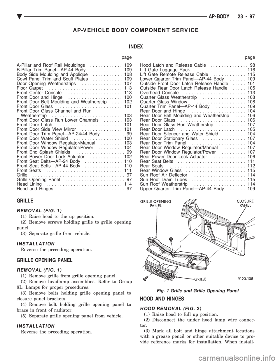
GRILLE
REMOVAL (FIG. 1)
(1) Raise hood to the up position.
(2) Remove screws holding grille to grille opening
panel. (3) Separate grille from vehicle.
INSTALLATION
Reverse the preceding operation.
GRILLE OPENING PANEL
REMOVAL (FIG. 1)
(1) Remove grille from grille opening panel.
(2) Remove headlamp assemblies. Refer to Group
8L. Lamps for proper procedures. (3) Remove bolts holding grille opening panel to
closure panel brackets. (4) Remove bolt holding grille opening panel to
brace in front of radiator. (5) Separate grille opening panel from vehicle.
INSTALLATION
Reverse the preceding operation.
HOOD AND HINGES
HOOD REMOVAL (FIG. 2)
(1) Raise hood to full up position.
(2) Disconnect the under hood lamp wire connec-
tor. (3) Mark all bolt and hinge attachment locations
with a grease pencil or other suitable device to pro-
vide reference marks for installation. When install-
Fig. 1 Grille and Grille Opening Panel
Ä AP-BODY 23 - 97
Page 2269 of 2438
REAR SEAT BACK INSTALLATION
Reverse the preceding operation.
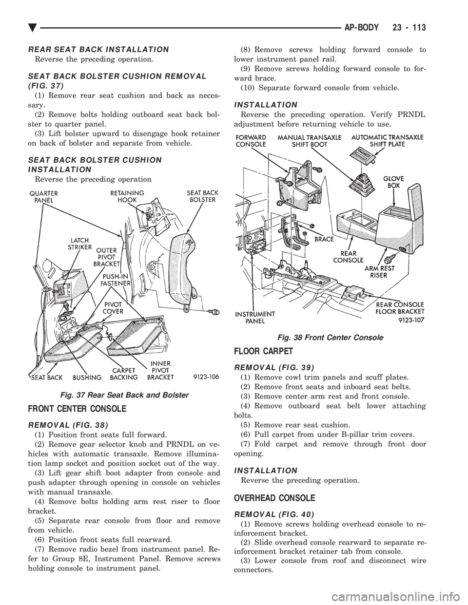
SEAT BACK BOLSTER CUSHION REMOVAL (FIG. 37)
(1) Remove rear seat cushion and back as neces-
sary. (2) Remove bolts holding outboard seat back bol-
ster to quarter panel. (3) Lift bolster upward to disengage hook retainer
on back of bolster and separate from vehicle.
SEAT BACK BOLSTER CUSHION INSTALLATION
Reverse the preceding operation
FRONT CENTER CONSOLE
REMOVAL (FIG. 38)
(1) Position front seats full forward.
(2) Remove gear selector knob and PRNDL on ve-
hicles with automatic transaxle. Remove illumina-
tion lamp socket and position socket out of the way. (3) Lift gear shift boot adapter from console and
push adapter through opening in console on vehicles
with manual transaxle. (4) Remove bolts holding arm rest riser to floor
bracket. (5) Separate rear console from floor and remove
from vehicle. (6) Position front seats full rearward.
(7) Remove radio bezel from instrument panel. Re-
fer to Group 8E, Instrument Panel. Remove screws
holding console to instrument panel. (8) Remove screws holding forward console to
lower instrument panel rail. (9) Remove screws holding forward console to for-
ward brace. (10) Separate forward console from vehicle.
INSTALLATION
Reverse the preceding operation. Verify PRNDL
adjustment before returning vehicle to use.
FLOOR CARPET
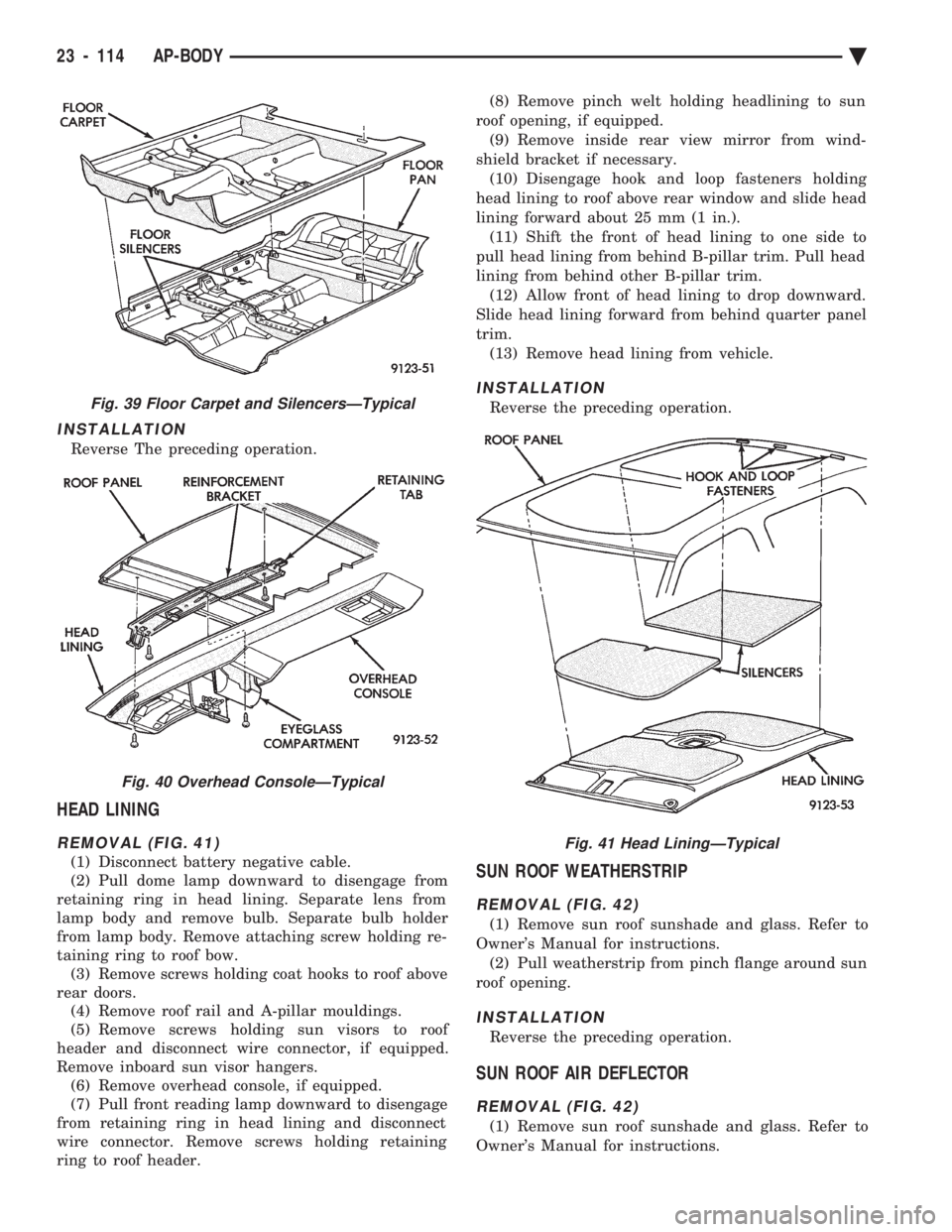
REMOVAL (FIG. 39)
(1) Remove cowl trim panels and scuff plates.
(2) Remove front seats and inboard seat belts.
(3) Remove center arm rest and front console.
(4) Remove outboard seat belt lower attaching
bolts. (5) Remove rear seat cushion.
(6) Pull carpet from under B-pillar trim covers.
(7) Fold carpet and remove through front door
opening.
INSTALLATION
Reverse the preceding operation.
OVERHEAD CONSOLE
REMOVAL (FIG. 40)
(1) Remove screws holding overhead console to re-
inforcement bracket. (2) Slide overhead console rearward to separate re-
inforcement bracket retainer tab from console. (3) Lower console from roof and disconnect wire
connectors.
Fig. 37 Rear Seat Back and Bolster
Fig. 38 Front Center Console
Ä AP-BODY 23 - 113
Page 2270 of 2438
INSTALLATION
Reverse The preceding operation.
HEAD LINING
REMOVAL (FIG. 41)
(1) Disconnect battery negative cable.
(2) Pull dome lamp downward to disengage from
retaining ring in head lining. Separate lens from
lamp body and remove bulb. Separate bulb holder
from lamp body. Remove attaching screw holding re-
taining ring to roof bow. (3) Remove screws holding coat hooks to roof above
rear doors. (4) Remove roof rail and A-pillar mouldings.
(5) Remove screws holding sun visors to roof
header and disconnect wire connector, if equipped.
Remove inboard sun visor hangers. (6) Remove overhead console, if equipped.
(7) Pull front reading lamp downward to disengage
from retaining ring in head lining and disconnect
wire connector. Remove screws holding retaining
ring to roof header. (8) Remove pinch welt holding headlining to sun
roof opening, if equipped. (9) Remove inside rear view mirror from wind-
shield bracket if necessary. (10) Disengage hook and loop fasteners holding
head lining to roof above rear window and slide head
lining forward about 25 mm (1 in.). (11) Shift the front of head lining to one side to
pull head lining from behind B-pillar trim. Pull head
lining from behind other B-pillar trim. (12) Allow front of head lining to drop downward.
Slide head lining forward from behind quarter panel
trim. (13) Remove head lining from vehicle.
INSTALLATION
Reverse the preceding operation.
SUN ROOF WEATHERSTRIP
REMOVAL (FIG. 42)
(1) Remove sun roof sunshade and glass. Refer to
Owner's Manual for instructions. (2) Pull weatherstrip from pinch flange around sun
roof opening.
INSTALLATION
Reverse the preceding operation.
SUN ROOF AIR DEFLECTOR
REMOVAL (FIG. 42)
(1) Remove sun roof sunshade and glass. Refer to
Owner's Manual for instructions.
Fig. 39 Floor Carpet and SilencersÐTypical
Fig. 40 Overhead ConsoleÐTypical
Fig. 41 Head LiningÐTypical
23 - 114 AP-BODY Ä
Page 2273 of 2438
AP/27-VEHICLE CONVERTIBLE BODY COMPONENT SERVICE INDEX
page page
A-Pillar and Windshield Header Weatherstrip . . . 117
Convertible Top Adjustments ............... 131
Convertible Top Header ................... 118
Convertible Top Latch Hooks ............... 131
Door Glass Alignment .................... 131
Door Glass Rear Channel ................. 127
Door Striker Guide ...................... 128
Forward Roof Rail ....................... 121
Fourth Roof Bow and Slat ................. 120
Fourth Roof Bow Slat .................... 132
Front Door Belt Moulding and Weatherstrip .... 127
Front Door Glass ........................ 125
Front Door Stationary Glass and Division Channel ............................. 126
Front Door Stationary Glass Channel Weatherstrip .......................... 126
Front Door Striker Guide Socket ............ 127
Front Seat Belt Retractor .................. 128
General Information ...................... 117
Quarter Glass and Roller Bracket ........... 132
Quarter Panel Belt Moulding ............... 129
Quarter Trim Panel ...................... 128
Rear Roof Rail ......................... 121
Rear Seat Back ......................... 128 Rear Seat Belt Retractor
.................. 129
Rear Tensioner Plate ..................... 132
Rear Window .......................... 122
Roof Linkage ........................... 121
Roof Rail Weatherstrip ................... 118
Roof Rail Weatherstrip Retainer ............. 131
Second Roof Bow and Linkage ............. 119
Sling-Well ............................. 124
Stationary Quarter Glass and Weatherstrip .... 121
Third Roof Bow ......................... 120
Top Cover ............................. 124
Top Frame ............................ 125
Top Header Trim Cover ................... 118
Top Latch ............................. 118
Top Lift Assist Cylinder ................... 122
Top Stack Down-Stop .................... 132
Top Stack Up-Stop ...................... 132
Trunk Hinge Lid ........................ 130
Trunk Lid .............................. 130
Trunk Lid Applique ...................... 130
Trunk Lid Lining ........................ 129
Trunk Opening Weatherstrip ............... 130
Windshield Header Lining ................. 117
Windshield Header Moulding ............... 117
GENERAL INFORMATION
This section will cover components that are unique
to the AP-vehicle convertible. All components that
are common to the AP-vehicle two door hardtop are
covered in the AP-Vehicle Body Components section.
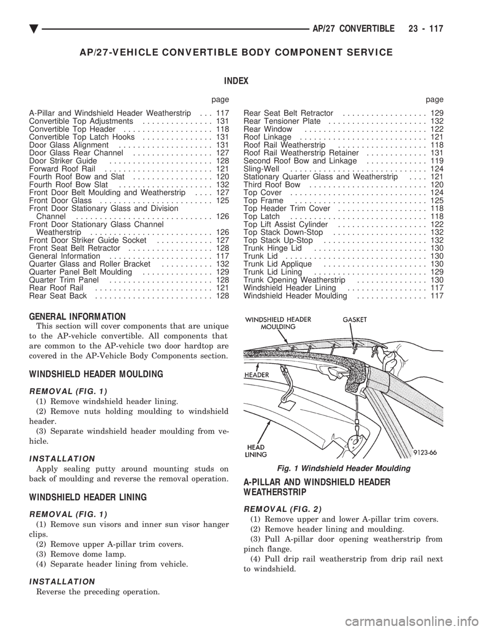
WINDSHIELD HEADER MOULDING
REMOVAL (FIG. 1)
(1) Remove windshield header lining.
(2) Remove nuts holding moulding to windshield
header. (3) Separate windshield header moulding from ve-
hicle.
INSTALLATION
Apply sealing putty around mounting studs on
back of moulding and reverse the removal operation.
WINDSHIELD HEADER LINING
REMOVAL (FIG. 1)
(1) Remove sun visors and inner sun visor hanger
clips. (2) Remove upper A-pillar trim covers.
(3) Remove dome lamp.
(4) Separate header lining from vehicle.
INSTALLATION
Reverse the preceding operation.
A-PILLAR AND WINDSHIELD HEADER
WEATHERSTRIP
REMOVAL (FIG. 2)
(1) Remove upper and lower A-pillar trim covers.
(2) Remove header lining and moulding.
(3) Pull A-pillar door opening weatherstrip from
pinch flange. (4) Pull drip rail weatherstrip from drip rail next
to windshield.
Fig. 1 Windshield Header Moulding
Ä AP/27 CONVERTIBLE 23 - 117