1993 CHEVROLET PLYMOUTH ACCLAIM air filter
[x] Cancel search: air filterPage 249 of 2438

(7) Install high pressure hose to hydraulic assem-
bly (Fig. 7). Tighten the hose, to hydraulic assembly
fitting to 16 N Im (145 in. lbs)
(8) Fill hydraulic assembly brake fluid reservoir to
top of screen on the reservoir filter/strainer Fig. 9.
(9) Connect all electrical connectors to the hydrau-
lic assembly. (10) Bleed the entire brake system, see Bleeding
Brake System in this section of the Service Manual. (11) Replace all fresh air intake ducts, air cleaner
and washer bottle. (12) Check that the brake fluid in the hydraulic
assembly is at the correct level before moving vehicle
(Fig. 9). (See Checking Brake Fluid Level in this sec-
tion of the service manual).
BRAKE FLUID RESERVOIR
REMOVE
(1) Fully de-pressurize the hydraulic accumulator
by pumping brake pedal a minimum of 40 times. Use
procedure described in De-Pressurizing Hydraulic Ac-
cumulator listed earlier in this section.
WARNING: FAILURE TO DE-PRESSURIZE HYDRAU-
LIC ACCUMULATOR, BEFORE PERFORMING THIS
OPERATION, MAY RESULT IN PERSONAL INJURY
AND/OR DAMAGE TO PAINTED SURFACES.
(2) Remove as much brake fluid as possible from
the fluid reservoir, using a syringe or equivalent
method. (3) Using Oil Filter Band Wrench, Special Tool
C-4065 or equivalent loosen bladder accumulator. Then remove the bladder accumulator and brake
fluid spray shield from the hydraulic assembly (Fig.
10). Remove high pressure banjo fitting from hydrau-
lic assembly.
(4) Using needle nose pliers, remove the three
fluid reservoir retaining pins from the hydraulic as-
sembly (Fig. 11). Compress the barb on the opposite
side of retaining pin to prevent pin from breaking.
(5) Remove reservoir from hydraulic assembly by
CAREFULLY prying between reservoir and hydrau-
Fig. 9 ABS Fill Level On Filter/Strainer
Fig. 10 Removing Bladder Accumulator
Fig. 11 Remove Reservoir Retaining Pins
Ä ANTI-LOCK 10 BRAKE SYSTEM 5 - 99
Page 252 of 2438
WARNING: FAILURE TO DE-PRESSURIZE HYDRAU-
LIC ASSEMBLY/ACCUMULATOR PRIOR PERFORM-
ING THIS OPERATION. MAY RESULT IN PERSONAL
INJURY AND/OR DAMAGE TO PAINTED SURFACES
OF THE VEHICLE.
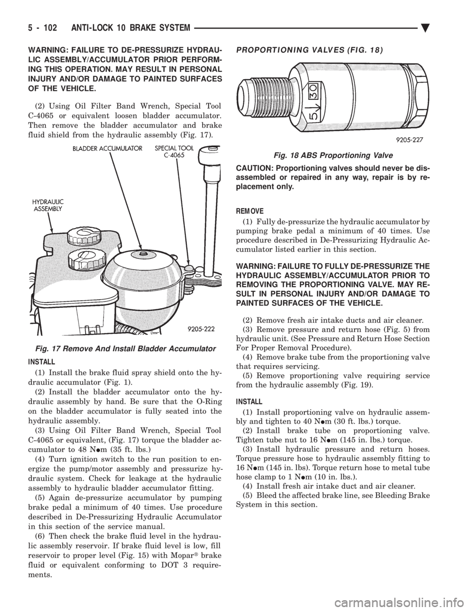
(2) Using Oil Filter Band Wrench, Special Tool
C-4065 or equivalent loosen bladder accumulator.
Then remove the bladder accumulator and brake
fluid shield from the hydraulic assembly (Fig. 17).
INSTALL
(1) Install the brake fluid spray shield onto the hy-
draulic accumulator (Fig. 1). (2) Install the bladder accumulator onto the hy-
draulic assembly by hand. Be sure that the O-Ring
on the bladder accumulator is fully seated into the
hydraulic assembly. (3) Using Oil Filter Band Wrench, Special Tool
C-4065 or equivalent, (Fig. 17) torque the bladder ac-
cumulator to 48 N Im (35 ft. lbs.)
(4) Turn ignition switch to the run position to en-
ergize the pump/motor assembly and pressurize hy-
draulic system. Check for leakage at the hydraulic
assembly to hydraulic bladder accumulator fitting. (5) Again de-pressurize accumulator by pumping
brake pedal a minimum of 40 times. Use procedure
described in De-Pressurizing Hydraulic Accumulator
in this section of the service manual. (6) Then check the brake fluid level in the hydrau-
lic assembly reservoir. If brake fluid level is low, fill
reservoir to proper level (Fig. 15) with Mopar tbrake
fluid or equivalent conforming to DOT 3 require-
ments.PROPORTIONING VALVES (FIG. 18)
CAUTION: Proportioning valves should never be dis-
assembled or repaired in any way, repair is by re-
placement only.
REMOVE (1) Fully de-pressurize the hydraulic accumulator by
pumping brake pedal a minimum of 40 times. Use
procedure described in De-Pressurizing Hydraulic Ac-
cumulator listed earlier in this section.
WARNING: FAILURE TO FULLY DE-PRESSURIZE THE
HYDRAULIC ASSEMBLY/ACCUMULATOR PRIOR TO
REMOVING THE PROPORTIONING VALVE. MAY RE-
SULT IN PERSONAL INJURY AND/OR DAMAGE TO
PAINTED SURFACES OF THE VEHICLE.
(2) Remove fresh air intake ducts and air cleaner.
(3) Remove pressure and return hose (Fig. 5) from
hydraulic unit. (See Pressure and Return Hose Section
For Proper Removal Procedure). (4) Remove brake tube from the proportioning valve
that requires servicing. (5) Remove proportioning valve requiring service
from the hydraulic assembly (Fig. 19).
INSTALL (1) Install proportioning valve on hydraulic assem-
bly and tighten to 40 N Im (30 ft. lbs.) torque.
(2) Install brake tube on proportioning valve.
Tighten tube nut to 16 N Im (145 in. lbs.) torque.
(3) Install hydraulic pressure and return hoses.
Torque pressure hose to hydraulic assembly fitting to
16 N Im (145 in. lbs). Torque return hose to metal tube
hose clamp to 1 N Im (10 in. lbs.).
(4) Install fresh air intake duct and air cleaner.
(5) Bleed the affected brake line, see Bleeding Brake
System in this section.
Fig. 17 Remove And Install Bladder Accumulator
Fig. 18 ABS Proportioning Valve
5 - 102 ANTI-LOCK 10 BRAKE SYSTEM Ä
Page 258 of 2438

CAUTION: Do not insert dual function pressure
switch into hydraulic assembly using the socket
and ratchet. Cross threading of the switch may oc-
cur. (1) Install the dual function pressure switch into
the hydraulic assembly by hand until the O-ring
seals are seated. (2) Using Socket, Special Tool 6607, (Fig. 10)
torque the dual function pressure switch into the hy-
draulic assembly to 12 N Im (9 ft. lbs.).
(3) Connect the wiring harness connectors (Fig. 9)
onto the dual function pressure switch and the boost
pressure transducer. Be sure the locking tabs on the
connectors are fully engaged on the switches. (4) Lower the vehicle.
(5) Turn the ignition switch to the on position and
let the system pressurize. Check for any leaks at the
dual function pressure switch. (6) Fully de-pressurize the hydraulic assembly a
second time. This will purge any air out that may
have entered hydraulic assembly when the switch
was removed. Turn the ignition switch to the on po-
sition and let the system pressurize again. (7) Road test vehicle to insure that the brake sys-
tem is performing correctly.
PRIMARY PRESSURE TRANSDUCER
REMOVE
WARNING: FAILURE TO FULLY DE-PRESSURIZE
THE HYDRAULIC BLADDER ACCUMULATOR PRIOR
TO REMOVING PRIMARY PRESSURE TRANS-
DUCER. WILL RESULT IN PERSONAL INJURY
AND/OR DAMAGE TO PAINTED SURFACES OF THE
VEHICLE.
To remove primary pressure transducer (Fig. 11),
from hydraulic assembly, removal of hydraulic as-
sembly from vehicle is notrequired.
(1) Fully de-pressurize the hydraulic accumulator
by pumping brake pedal a minimum of 40 times. Use
procedure described in De-Pressurizing Hydraulic Ac-
cumulator listed earlier in this section. (2) Remove as much brake fluid as possible from
the brake fluid reservoir, using a syringe or equiva-
lent method. (3) Using oil filter band wrench, Special Tool
C-4065 or equivalent, (Fig. 12) loosen bladder accu-
mulator. Then remove bladder accumulator and
brake fluid spray shield from hydraulic assembly. (4) Remove high pressure banjo fitting (Fig. 13)
from hydraulic assembly. (5) Using needle nose pliers, remove the 3 fluid
reservoir retaining pins from the hydraulic assembly
(Fig. 14). Compress barb on opposite side of retaining
pin, to prevent pin from breaking. CAUTION: Be extremely careful during the following
procedure to avoid damaging or puncturing brake
fluid reservoir during its removal.
(6) Remove brake fluid reservoir from hydraulic
assembly by carefullyprying between reservoir and
hydraulic assembly using a blunt pry bar (Fig. 15).
Use a rocking motion to help disengage reservoir
from grommets while prying. (7) Remove brake fluid level sensor from reservoir
and remove fluid reservoir from vehicle. (8) Remove hydraulic assembly wiring harness
connector from the primary pressure transducer (Fig.
16).
Fig. 11 Primary Pressure Transducer Location On Hydraulic Assembly
Fig. 12 Removing Bladder Accumulator
5 - 108 ANTI-LOCK 10 BRAKE SYSTEM Ä
Page 261 of 2438

INSTALL (1) Install differential pressure switch into hydrau-
lic assembly by hand, until fully threaded into hy-
draulic assembly. Then torque differential pressure
switch, into hydraulic assembly, using Socket, Spe-
cial Tool 6684, to 1.5 N Im (13 in. lbs.).
(2) Lower vehicle
(3) Connect differential pressure switch wiring
harness connector into hydraulic assembly wiring
harness (Fig. 19). (4) Connect the hydraulic assembly wiring harness
connector into the primary pressure transducer (Fig.
19). (5) Turn the ignition switch to the on position and
let the system pressurize. Check for any signs of
leakage at the differential pressure switch. (6) Fully de-pressurize the hydraulic assembly a
second time to purge any air out that may have en-
tered hydraulic assembly when the differential pres-
sure switch was removed. Turn the ignition switch to
the on position and let the system pressurize again. (7) Fill hydraulic assembly fluid reservoir to the
top of the screen on the filter rainer. Use only fresh
clean brake fluid conforming to DOT 3 requirements,
such as Mopar tor equivalent.
(8) Road test vehicle to insure that the brake sys-
tem is performing correctly.
BOOST PRESSURE TRANSDUCER
REMOVE
WARNING: FAILURE TO FULLY DE-PRESSURIZE
THE HYDRAULIC BLADDER ACCUMULATOR PRIOR
TO REMOVING BOOST PRESSURE TRANSDUCER.
MAY RESULT IN PERSONAL INJURY AND/OR DAM-
AGE TO PAINTED SURFACES OF THE VEHICLE. To remove the boost pressure transducer (Fig. 21),
from the hydraulic assembly, removal of the hydrau-
lic assembly from the vehicle is notrequired.
(1) De-pressurize hydraulic bladder accumulator on
hydraulic assembly by pumping the brake pedal a
minimum of 40 times. Refer to the procedure as de-
scribed in De-Pressurizing Hydraulic Accumulator
listed earlier in this section. (2) Raise vehicle on a frame contact type hoist. See
Hoisting in the Lubrication And Maintenance section
of this manual, for the required lifting procedure to
be used for this vehicle. (3) Disconnect hydraulic assembly wiring harness
connectors from the dual function pressure switch
and boost pressure transducer (Fig. 21). (4) Using a long extension and Socket, Special Tool
6607, remove dual function pressure switch from bot-
tom of hydraulic assembly (Fig. 22)
(5) Remove boost pressure transducer from hydrau-
lic assembly, from under vehicle using a long exten-
sion and Socket, Special Tool 6684 (Fig. 23).
Fig. 20 Differential Pressure Switch Removal And Replacement
Fig. 21 Boost Pressure Transducer Location
Fig. 22 Remove And Install Dual Function Pressure Switch
Ä ANTI-LOCK 10 BRAKE SYSTEM 5 - 111
Page 262 of 2438
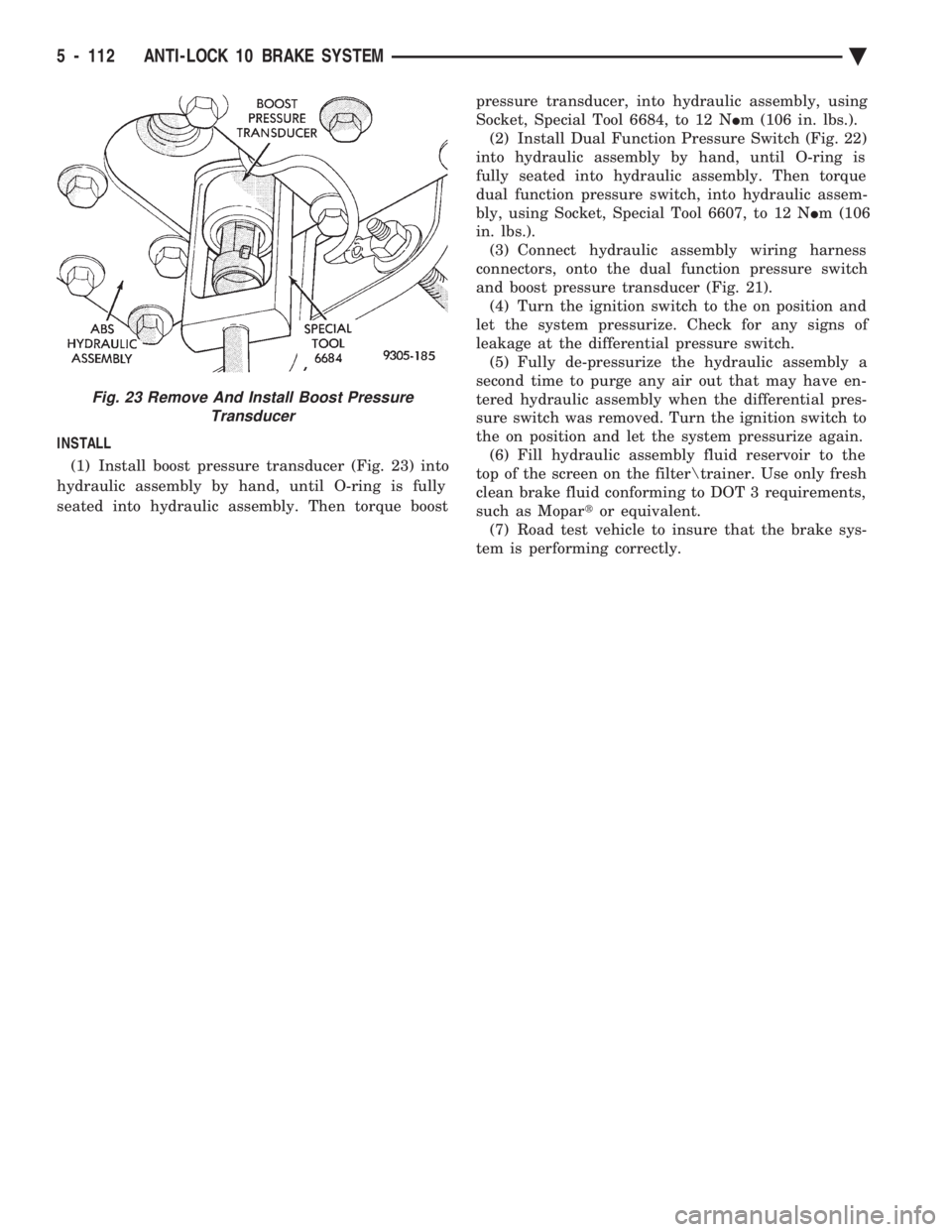
INSTALL (1) Install boost pressure transducer (Fig. 23) into
hydraulic assembly by hand, until O-ring is fully
seated into hydraulic assembly. Then torque boost pressure transducer, into hydraulic assembly, using
Socket, Special Tool 6684, to 12 N Im (106 in. lbs.).
(2) Install Dual Function Pressure Switch (Fig. 22)
into hydraulic assembly by hand, until O-ring is
fully seated into hydraulic assembly. Then torque
dual function pressure switch, into hydraulic assem-
bly, using Socket, Special Tool 6607, to 12 N Im (106
in. lbs.). (3) Connect hydraulic assembly wiring harness
connectors, onto the dual function pressure switch
and boost pressure transducer (Fig. 21). (4) Turn the ignition switch to the on position and
let the system pressurize. Check for any signs of
leakage at the differential pressure switch. (5) Fully de-pressurize the hydraulic assembly a
second time to purge any air out that may have en-
tered hydraulic assembly when the differential pres-
sure switch was removed. Turn the ignition switch to
the on position and let the system pressurize again. (6) Fill hydraulic assembly fluid reservoir to the
top of the screen on the filter rainer. Use only fresh
clean brake fluid conforming to DOT 3 requirements,
such as Mopar tor equivalent.
(7) Road test vehicle to insure that the brake sys-
tem is performing correctly.
Fig. 23 Remove And Install Boost Pressure Transducer
5 - 112 ANTI-LOCK 10 BRAKE SYSTEM Ä
Page 1568 of 2438
The MOPAR Silicone Rubber Adhesive Sealant
gasket material or equivalent should be applied in a
continuous bead approximately 3mm (0.120 inch) in
diameter. All mounting holes must be circled. For
corner sealing, a 3.17 or 6.35 mm (1/8 or 1/4 inch.)
drop is placed in the center of the gasket contact
area. Uncured sealant may be removed with a shop
towels. Components should be torqued in place while
the sealant is still wet to the touch (within 10 min-
utes). The usage of a locating dowel is recommended
during assembly to prevent smearing of material off
location.
CRANKSHAFT SPROCKET BOLT ACCESS PLUG
An Access plug is located in the right inner fender
shield. Remove the plug and insert proper size
socket, extension and rachet, when crankshaft rota-
tion is necessary.
ENGINE PERFORMANCE
If a loss of performance is noticed, ignition timing
should be checked. If ignition timing is retarded by
9, 18 or 27É indicating 1, 2 or 3 (timing belt or chain)
teeth may have skipped, then, camshaft and acces-
sory shaft timing with the crankshaft should be
checked. Refer to Engine Timing Sprockets and Oil
Seals of the Engine Section. To provide best vehicle performance and lowest ve-
hicle emissions, it is most important that the tune-up
be done accurately. Use the specifications listed on
the Vehicle Emission Control Information label
found in the engine compartment. (1) Test cranking amperage draw. See Starting
Motor Cranking Amperage Draw Electrical Section
of this manual. (2) Tighten the intake manifold bolts to specifica-
tions. (3) Perform cylinder compression test.(a) Check engine oil level and add oil if neces-
sary. (b) Drive the vehicle until engine reaches normal
operating temperature. (c) Select a route free from traffic and other
forms of congestion, observe all traffic laws, and ac-
celerate through the gears several times briskly.
CAUTION: Do not overspeed the engine. The higher
engine speed may help clean out valve seat deposits
which can prevent accurate compression readings.
(d) Remove all spark plugs from engine. As
spark plugs are being removed, check electrodes for
abnormal firing indicators fouled, hot, oily, etc.
Record cylinder number of spark plug for future
reference. (e) Disconnect coil wire from distributor and se-
cure to good ground to prevent a spark from start- ing a fire (Conventional Ignition System). For Direct
Ignition System DIS disconnect the coil connector. (f) Be sure throttle blade is fully open during the
compression check. (g) Insert compression gage adaptor into the #1
spark plug hole in cylinder head. Crank engine until
maximum pressure is reached on gage. Record this
pressure as #1 cylinder pressure. (h) Repeat Step G for all remaining cylinders.
(i) Compression should not be less than (689kPa)
100 psi and not vary more than 25 percent from
cylinder to cylinder. (j) If one or more cylinders have abnormally low
compression pressures, repeat steps 3b through 3h. (k) If the same cylinder or cylinders repeat an
abnormally low reading on the second compression
test, it could indicate the existence of a problem in
the cylinder in question.
The recommended compression pressures are
to be used only as a guide to diagnosing engine
problems. An engine should not be disassembled
to determine the cause of low compression un-
less some malfunction is present. (4) Clean or replace spark plugs as necessary and
adjust gap as specified in Electrical Group 8. Tighten to
specifications. (5) Test resistance of spark plug cables. Refer to
Ignition System Secondary Circuit Inspection Electri-
cal Section Group 8. (6) Inspect the primary wire. Test coil output volt-
age, primary and secondary resistance. Replace parts
as necessary. Refer to Ignition System and make nec-
essary adjustment. (7) Ignition timing should be set to specifications.
(See Specification Label in engine compartment). (8) Test fuel pump for pressure and vacuum. Refer to
Fuel System Group 14, Specifications. (9) The air filter elements should be replaced as
specified in Lubrication and Maintenance, Group 0. (10) Inspect crankcase ventilation system as out
lined in Lubrication and Maintenance, Group 0. For
emission controls see Emission Controls Group 25 for
service procedures. (11) Inspect and adjust accessory belt drives refer-
ring to Accessory Belt Drive in Cooling System, Group
7 for proper adjustments. (12) Road test vehicle as a final test.
HONING CYLINDER BORES
Before honing, stuff plenty of clean shop towels
under the bores, over the crankshaft to keep abrasive
materials from entering crankcase area. (1) Used carefully, the cylinder bore resizing hone
C-823 equipped with 220 grit stones, is the best tool for
this job. In addition to deglazing, it will reduce taper
and out-of-round as well as removing light
9 - 2 ENGINE Ä
Page 1571 of 2438
CAUTION: Be sure that the tapped holes maintain
the original centerline.
Heli-Coil tools and inserts are readily available
from automotive parts jobbers.
HYDROSTATIC LOCKED ENGINE
When an engine is suspected to be hydrostaticly
locked, regardless of what caused the problem, these
steps should be used.
CAUTION: Do Not Use Starter Motor To Rotate En-
gine, severe damage may occur.
(1) Inspect air cleaner, induction system and in-
take manifold to insure system is dry and clear of
foreign material. (2) Remove negative battery cable.
(3) Place a shop towel around the spark plugs
when removing them from the engine. This will
catch any fluid that may possibly be in the cylinder
under pressure. (4) With all spark plugs removed, rotate engine
crankshaft using a breaker bar and socket. (5) Identify the fluid in the cylinder(s) (i.e., cool-
ant, fuel, oil or other). (6) Make sure all fluid has been removed from the
cylinders. Inspect engine for damage (i.e., Connecting
Rods, Pistons, Valves etc.) (7) Repair engine or components as necessary to
prevent this problem from occurring again.
CAUTION: Squirt approximately 1 teaspoon of oil
into cylinders, rotate engine to lubricate the cylin-
der walls to prevent damage on restart.
(8) Install new spark plugs.
(9) Drain engine oil and remove oil filter.
(10) Fill engine with specified amount of approved
oil and install new oil filter. (11) Connect negative battery cable.
(12) Start engine and check for any leaks.
Ä ENGINE 9 - 5
Page 1579 of 2438
² Drive shaft distress: See Driveshafts in Suspension,
Group 2.
² Any front end structural damage (after repair).
² Insulator replacement.
ENGINE MOUNT INSULATOR ADJUSTMENT
(1) Remove the load on the engine motor mounts by
carefully supporting the engine and transmission as-
sembly with a floor jack. (2) Loosen the right engine mount insulator vertical
fasteners, and the front engine mount bracket to front
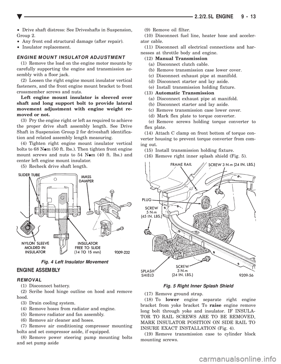
crossmember screws and nuts. Left engine mount insulator is sleeved over
shaft and long support bolt to provide lateral
movement adjustment with engine weight re-
moved or not. (3) Pry the engine right or left as required to achieve
the proper drive shaft assembly length. See Drive
Shaft in Suspension Group 2 for driveshaft identifica-
tion and related assembly length measuring. (4) Tighten right engine mount insulator vertical
bolts to 68 N Im (50 ft. lbs.). Then tighten front engine
mount screws and nuts to 54 N Im (40 ft. lbs.) and
center left engine mount insulator. (5) Recheck drive shaft length.
ENGINE ASSEMBLY
REMOVAL
(1) Disconnect battery.
(2) Scribe hood hinge outline on hood and remove
hood. (3) Drain cooling system.
(4) Remove hoses from radiator and engine.
(5) Remove radiator and fan assembly.
(6) Remove air cleaner and hoses.
(7) Remove air conditioning compressor mounting
bolts and set compressor aside, if equipped. (8) Remove power steering pump mounting bolts
and set pump aside (9) Remove oil filter.
(10) Disconnect fuel line, heater hose and acceler-
ator cable. (11) Disconnect all electrical connections and har-
nesses at throttle body and engine. (12) Manual Transmission
(a) Disconnect clutch cable.
(b) Remove transmission case lower cover.
(c) Disconnect exhaust pipe at manifold.
(d) Disconnect starter and lay aside.
(e) Install transmission holding fixture.
(13) Automatic Transmission
(a) Disconnect exhaust pipe at manifold.
(b) Disconnect starter and lay aside.
(c) Remove transmission case lower cover.
(d) Mark flex plate to torque converter.
(e) Remove screws holding torque converter to
flex plate.
(14) Attach C clamp on front bottom of torque con-
verter housing to prevent torque converter from com-
ing out. (15) Install transmission holding fixture.
(16) Remove right inner splash shield (Fig. 5).
(17) Remove ground strap.
(18) To lowerengine separate right engine
bracket from yoke bracket To raiseengine remove
long bolt through yoke and insulator. IF INSULA-
TOR TO RAIL SCREWS ARE TO BE REMOVED,
MARK INSULATOR POSITION ON SIDE RAIL TO
INSURE EXACT INSTALLATION (Fig. 4). (19) Remove transmission case to cylinder block
mounting screws.Fig. 5 Right Inner Splash Shield
Fig. 4 Left Insulator Movement
Ä 2.2/2.5L ENGINE 9 - 13