1993 CHEVROLET PLYMOUTH ACCLAIM rear view mirror
[x] Cancel search: rear view mirrorPage 2282 of 2438
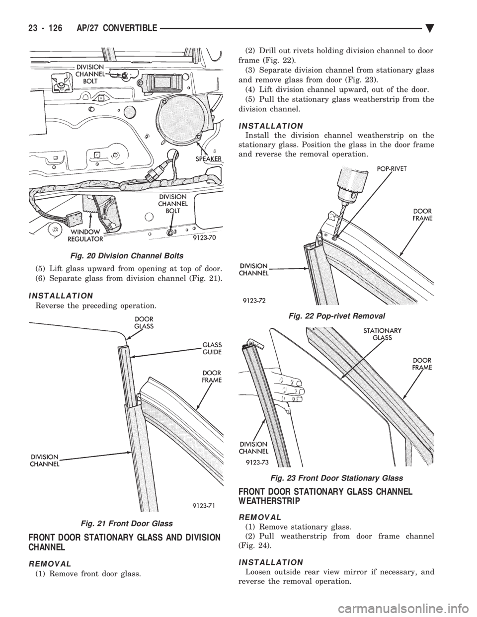
(5) Lift glass upward from opening at top of door.
(6) Separate glass from division channel (Fig. 21).
INSTALLATION
Reverse the preceding operation.
FRONT DOOR STATIONARY GLASS AND DIVISION
CHANNEL
REMOVAL
(1) Remove front door glass. (2) Drill out rivets holding division channel to door
frame (Fig. 22). (3) Separate division channel from stationary glass
and remove glass from door (Fig. 23). (4) Lift division channel upward, out of the door.
(5) Pull the stationary glass weatherstrip from the
division channel.
INSTALLATION
Install the division channel weatherstrip on the
stationary glass. Position the glass in the door frame
and reverse the removal operation.
FRONT DOOR STATIONARY GLASS CHANNEL
WEATHERSTRIP
REMOVAL
(1) Remove stationary glass.
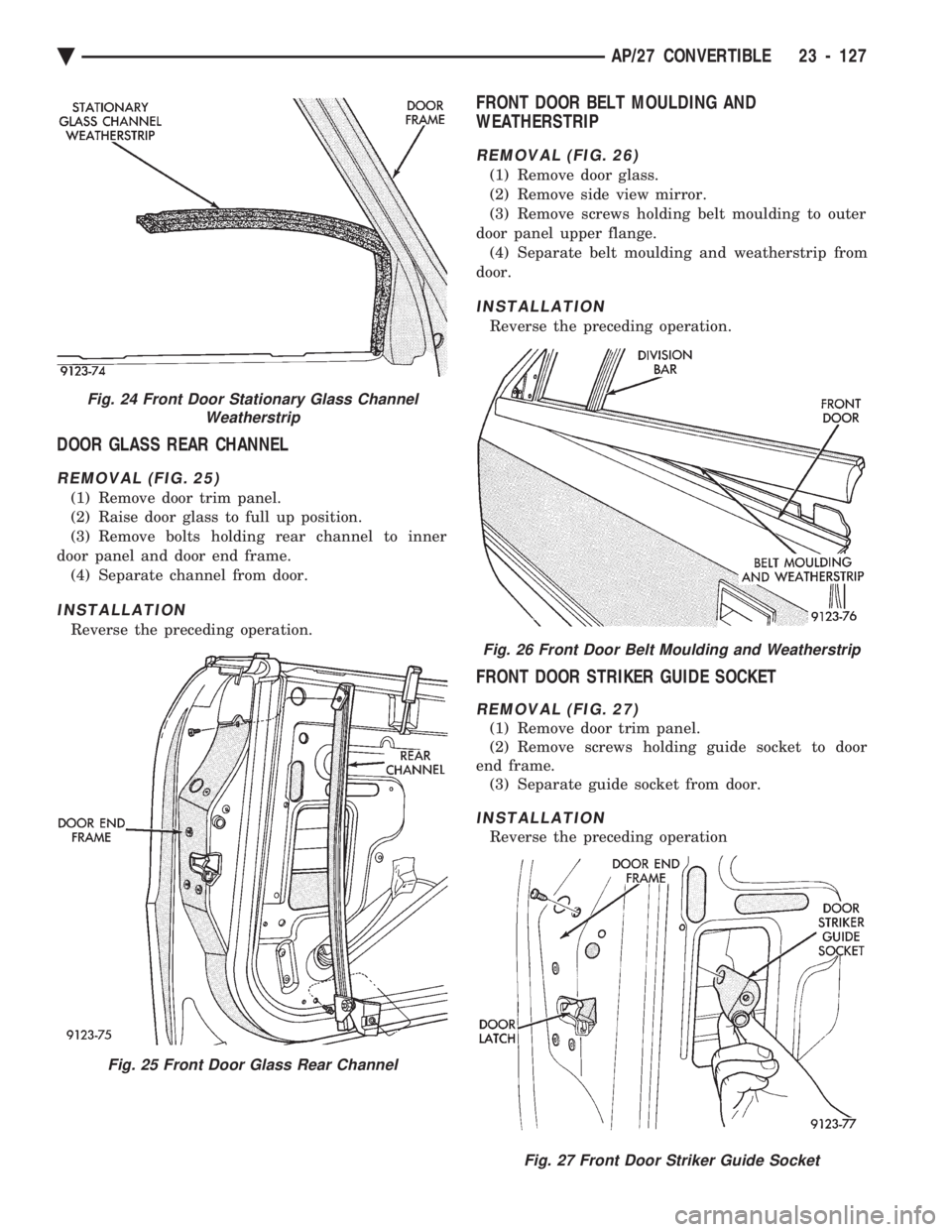
(2) Pull weatherstrip from door frame channel
(Fig. 24).
INSTALLATION
Loosen outside rear view mirror if necessary, and
reverse the removal operation.
Fig. 20 Division Channel Bolts
Fig. 21 Front Door Glass
Fig. 22 Pop-rivet Removal
Fig. 23 Front Door Stationary Glass
23 - 126 AP/27 CONVERTIBLE Ä
Page 2283 of 2438
DOOR GLASS REAR CHANNEL
REMOVAL (FIG. 25)
(1) Remove door trim panel.
(2) Raise door glass to full up position.
(3) Remove bolts holding rear channel to inner
door panel and door end frame. (4) Separate channel from door.
INSTALLATION
Reverse the preceding operation.
FRONT DOOR BELT MOULDING AND
WEATHERSTRIP
REMOVAL (FIG. 26)
(1) Remove door glass.
(2) Remove side view mirror.
(3) Remove screws holding belt moulding to outer
door panel upper flange. (4) Separate belt moulding and weatherstrip from
door.
INSTALLATION
Reverse the preceding operation.
FRONT DOOR STRIKER GUIDE SOCKET
REMOVAL (FIG. 27)
(1) Remove door trim panel.
(2) Remove screws holding guide socket to door
end frame. (3) Separate guide socket from door.
INSTALLATION
Reverse the preceding operation
Fig. 24 Front Door Stationary Glass Channel Weatherstrip
Fig. 25 Front Door Glass Rear Channel
Fig. 26 Front Door Belt Moulding and Weatherstrip
Fig. 27 Front Door Striker Guide Socket
Ä AP/27 CONVERTIBLE 23 - 127
Page 2289 of 2438
AY-VEHICLE BODY COMPONENT SERVICE INDEX
page page
A-Pillar and Roof Rail Mouldings ............ 143
B-Pillar Trim Panel ...................... 143
Body Mouldings ......................... 146
Cowl Panel Trim and Scuff Plates ........... 143
Door Frame Trim Moulding ................ 137
Front Door and Hinge .................... 137
Front Door Glass ........................ 139
Front Door Latch ........................ 138
Front Door Silencer and Water Shield ........ 137
Front Door Trim Panel .................... 136
Front Door Window Regulator .............. 138
Front End Splash Shields ................. 136
Front Seat Belts ........................ 144
Front Seats ............................ 145
Grille AY/P Body ........................ 133
Grille AY/S Body ........................ 133
Grille Opening Panel AY/P Body ............ 134
Grille Opening Panel AY/S Body ............ 134
Head Lining ............................ 142
Hood and Hinges ....................... 134
Hood Latch and Release Cable ............. 135
Hood Ornament AY/P-S .................. 134
Outside Door Handle ..................... 138
Overhead Console ....................... 142 Quarter Trim Panel
...................... 143
Rear Deck Filler Panel ................... 146
Rear Door and Hinge .................... 140
Rear Door Fixed Glass Outer Cover ÐAY-S Body ......................... 141
Rear Door Fixed Window Module ........... 142
Rear Door Frame Trim Moulding ............ 139
Rear Door Glass ........................ 141
Rear Door Glass Lift Plate and Guide Bar ..... 141
Rear Door Latch ........................ 140
Rear Door Outer CoverÐAY-P Body ......... 141
Rear Door Outside Handle ................ 140
Rear Door Silencer and Water Shield ........ 140
Rear Door Trim Panel .................... 139
Rear Door Window Regulator .............. 141
Rear Seat Belts ......................... 144
Rear Seats ............................ 145
Rear Shelf Trim Panel .................... 144
Rear Window Glass ...................... 147
Side View Mirror Trim Cover ............... 137
Trunk Lid .............................. 147
Trunk Lid Hinge ........................ 147
Trunk Lid Torsion Bar .................... 148
Vinyl Roof Bonnet ....................... 146
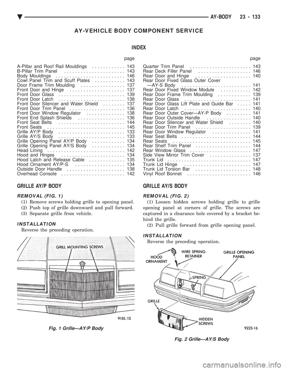
GRILLE AY/P BODY
REMOVAL (FIG. 1)
(1) Remove screws holding grille to opening panel.
(2) Push top of grille downward and pull forward.
(3) Separate grille from vehicle.
INSTALLATION
Reverse the preceding operation.
GRILLE AY/S BODY
REMOVAL (FIG. 2)
(1) Loosen hidden screws holding grille to grille
opening panel at corners of grille. The screws are
captured in a clearance hole covered by a bracket be-
hind the grille. (2) Pull grille forward from grille opening panel.
INSTALLATION
Reverse the preceding operation.
Fig. 1 GrilleÐAY/P Body
Fig. 2 GrilleÐAY/S Body
Ä AY-BODY 23 - 133
Page 2295 of 2438
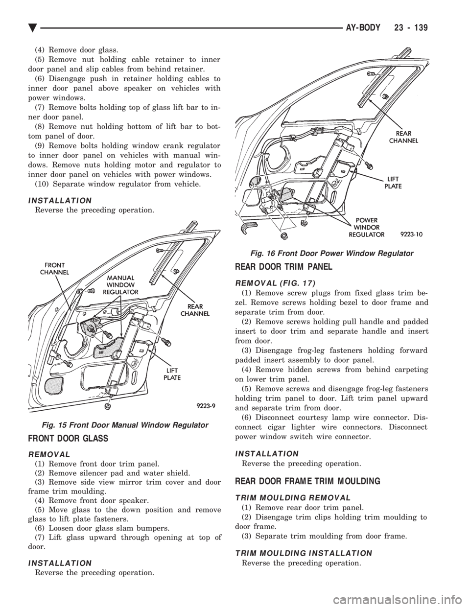
(4) Remove door glass.
(5) Remove nut holding cable retainer to inner
door panel and slip cables from behind retainer. (6) Disengage push in retainer holding cables to
inner door panel above speaker on vehicles with
power windows. (7) Remove bolts holding top of glass lift bar to in-
ner door panel. (8) Remove nut holding bottom of lift bar to bot-
tom panel of door. (9) Remove bolts holding window crank regulator
to inner door panel on vehicles with manual win-
dows. Remove nuts holding motor and regulator to
inner door panel on vehicles with power windows. (10) Separate window regulator from vehicle.
INSTALLATION
Reverse the preceding operation.
FRONT DOOR GLASS
REMOVAL
(1) Remove front door trim panel.
(2) Remove silencer pad and water shield.
(3) Remove side view mirror trim cover and door
frame trim moulding. (4) Remove front door speaker.
(5) Move glass to the down position and remove
glass to lift plate fasteners. (6) Loosen door glass slam bumpers.
(7) Lift glass upward through opening at top of
door.
INSTALLATION
Reverse the preceding operation.
REAR DOOR TRIM PANEL
REMOVAL (FIG. 17)
(1) Remove screw plugs from fixed glass trim be-
zel. Remove screws holding bezel to door frame and
separate trim from door. (2) Remove screws holding pull handle and padded
insert to door trim and separate handle and insert
from door. (3) Disengage frog-leg fasteners holding forward
padded insert assembly to door panel. (4) Remove hidden screws from behind carpeting
on lower trim panel. (5) Remove screws and disengage frog-leg fasteners
holding trim panel to door. Lift trim panel upward
and separate trim from door. (6) Disconnect courtesy lamp wire connector. Dis-
connect cigar lighter wire connectors. Disconnect
power window switch wire connector.
INSTALLATION
Reverse the preceding operation.
REAR DOOR FRAME TRIM MOULDING
TRIM MOULDING REMOVAL
(1) Remove rear door trim panel.
(2) Disengage trim clips holding trim moulding to
door frame. (3) Separate trim moulding from door frame.
TRIM MOULDING INSTALLATION
Reverse the preceding operation.
Fig. 15 Front Door Manual Window Regulator
Fig. 16 Front Door Power Window Regulator
Ä AY-BODY 23 - 139
Page 2298 of 2438
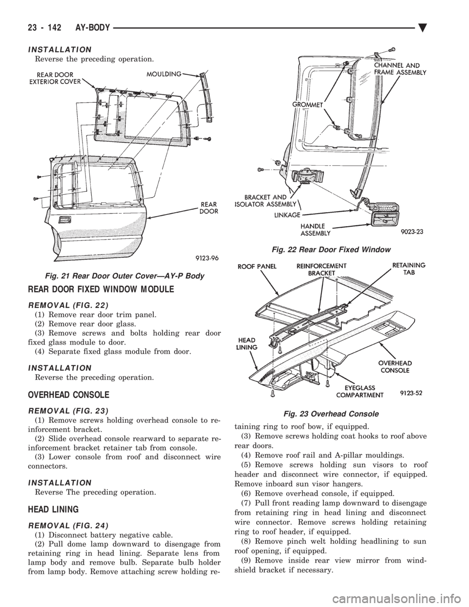
INSTALLATION
Reverse the preceding operation.
REAR DOOR FIXED WINDOW MODULE
REMOVAL (FIG. 22)
(1) Remove rear door trim panel.
(2) Remove rear door glass.
(3) Remove screws and bolts holding rear door
fixed glass module to door. (4) Separate fixed glass module from door.
INSTALLATION
Reverse the preceding operation.
OVERHEAD CONSOLE
REMOVAL (FIG. 23)
(1) Remove screws holding overhead console to re-
inforcement bracket. (2) Slide overhead console rearward to separate re-
inforcement bracket retainer tab from console. (3) Lower console from roof and disconnect wire
connectors.
INSTALLATION
Reverse The preceding operation.
HEAD LINING
REMOVAL (FIG. 24)
(1) Disconnect battery negative cable.
(2) Pull dome lamp downward to disengage from
retaining ring in head lining. Separate lens from
lamp body and remove bulb. Separate bulb holder
from lamp body. Remove attaching screw holding re- taining ring to roof bow, if equipped.
(3) Remove screws holding coat hooks to roof above
rear doors. (4) Remove roof rail and A-pillar mouldings.
(5) Remove screws holding sun visors to roof
header and disconnect wire connector, if equipped.
Remove inboard sun visor hangers. (6) Remove overhead console, if equipped.
(7) Pull front reading lamp downward to disengage
from retaining ring in head lining and disconnect
wire connector. Remove screws holding retaining
ring to roof header, if equipped. (8) Remove pinch welt holding headlining to sun
roof opening, if equipped. (9) Remove inside rear view mirror from wind-
shield bracket if necessary.
Fig. 21 Rear Door Outer CoverÐAY-P Body
Fig. 22 Rear Door Fixed Window
Fig. 23 Overhead Console
23 - 142 AY-BODY Ä