1993 CHEVROLET PLYMOUTH ACCLAIM run flat
[x] Cancel search: run flatPage 2154 of 2438

WHEELS SERVICE PROCEDURES INDEX
page page
General Information ........................ 6
Tire and Wheel Balance .................... 6
Tire and Wheel Run Out .................... 7 Wheel Installation
......................... 6
Wheel Replacement ....................... 6
GENERAL INFORMATION
Original equipment wheels are designed for proper
operation at all loads up to the maximum vehicle ca-
pacity. All models use steel or cast aluminum drop center
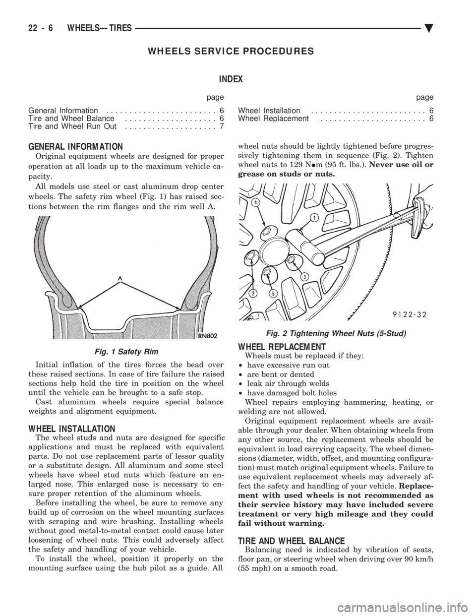
wheels. The safety rim wheel (Fig. 1) has raised sec-
tions between the rim flanges and the rim well A.
Initial inflation of the tires forces the bead over
these raised sections. In case of tire failure the raised
sections help hold the tire in position on the wheel
until the vehicle can be brought to a safe stop. Cast aluminum wheels require special balance
weights and alignment equipment.
WHEEL INSTALLATION
The wheel studs and nuts are designed for specific
applications and must be replaced with equivalent
parts. Do not use replacement parts of lessor quality
or a substitute design. All aluminum and some steel
wheels have wheel stud nuts which feature an en-
larged nose. This enlarged nose is necessary to en-
sure proper retention of the aluminum wheels. Before installing the wheel, be sure to remove any
build up of corrosion on the wheel mounting surfaces
with scraping and wire brushing. Installing wheels
without good metal-to-metal contact could cause later
loosening of wheel nuts. This could adversely affect
the safety and handling of your vehicle. To install the wheel, position it properly on the
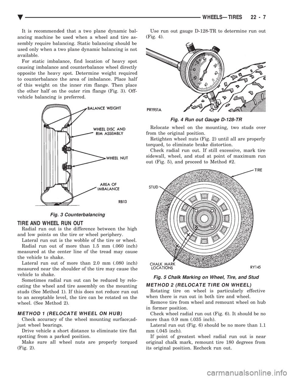
mounting surface using the hub pilot as a guide. All wheel nuts should be lightly tightened before progres-
sively tightening them in sequence (Fig. 2). Tighten
wheel nuts to 129 N Im (95 ft. lbs.). Never use oil or
grease on studs or nuts.
WHEEL REPLACEMENT
Wheels must be replaced if they:
² have excessive run out
² are bent or dented
² leak air through welds
² have damaged bolt holes
Wheel repairs employing hammering, heating, or
welding are not allowed. Original equipment replacement wheels are avail-
able through your dealer. When obtaining wheels from
any other source, the replacement wheels should be
equivalent in load carrying capacity. The wheel dimen-
sions (diameter, width, offset, and mounting configura-
tion) must match original equipment wheels. Failure to
use equivalent replacement wheels may adversely af-
fect the safety and handling of your vehicle. Replace-
ment with used wheels is not recommended as
their service history may have included severe
treatment or very high mileage and they could
fail without warning.
TIRE AND WHEEL BALANCE
Balancing need is indicated by vibration of seats,
floor pan, or steering wheel when driving over 90 km/h
(55 mph) on a smooth road.
Fig. 1 Safety Rim
Fig. 2 Tightening Wheel Nuts (5-Stud)
22 - 6 WHEELSÐTIRES Ä
Page 2155 of 2438

It is recommended that a two plane dynamic bal-
ancing machine be used when a wheel and tire as-
sembly require balancing. Static balancing should be
used only when a two plane dynamic balancing is not
available. For static imbalance, find location of heavy spot
causing imbalance and counterbalance wheel directly
opposite the heavy spot. Determine weight required
to counterbalance the area of imbalance. Place half
of this weight on the inner rim flange. Then place
the other half on the outer rim flange (Fig. 3). Off-
vehicle balancing is preferred.
TIRE AND WHEEL RUN OUT
Radial run out is the difference between the high
and low points on the tire or wheel periphery. Lateral run out is the wobble of the tire or wheel.
Radial run out of more than 1.5 mm (.060 inch)
measured at the center line of the tread may cause
the vehicle to shake. Lateral run out of more than 2.0 mm (.080 inch)
measured near the shoulder of the tire may cause the
vehicle to shake. Sometimes radial run out can be reduced by relo-
cating the wheel and tire assembly on the mounting
studs (See Method 1). If this does not reduce run out
to an acceptable level, the tire can be rotated on the
wheel. (See Method 2).
METHOD 1 (RELOCATE WHEEL ON HUB)
Check accuracy of the wheel mounting surface;ad-
just wheel bearings. Drive vehicle a short distance to eliminate tire flat
spotting from a parked position. Make sure all wheel nuts are properly torqued
(Fig. 2). Use run out gauge D-128-TR to determine run out
(Fig. 4).
Relocate wheel on the mounting, two studs over
from the original position. Retighten wheel nuts (Fig. 2) until all are properly
torqued, to eliminate brake distortion. Check radial run out. If still excessive, mark tire
sidewall, wheel, and stud at point of maximum run
out (Fig. 5), and proceed to Method #2.
METHOD 2 (RELOCATE TIRE ON WHEEL)
Rotating tire on wheel is particularly effective
when there is run out in both tire and wheel. Remove tire from wheel and remount wheel on hub
in former position. Check wheel radial run out (Fig. 6). It should be no
more than 0.9 mm (.035 inch). Lateral run out (Fig. 6) should be no more than 1.1
mm (.045 inch). If point of greatest wheel radial run out is near
original chalk mark, remount tire 180 degrees from
its original position. Recheck run out.
Fig. 3 Counterbalancing
Fig. 4 Run out Gauge D-128-TR
Fig. 5 Chalk Marking on Wheel, Tire, and Stud
Ä WHEELSÐTIRES 22 - 7
Page 2280 of 2438

(7) Install lower portion of rear window in position
on rear tack strip, align to the bottom center mark. (8) Staple the corners of the rear window valance
and carrier to the rear tack strip. Verify the edges
are even. (9) Position rear stay pads and suspender straps
over fourth roof bow and over the outboard ends of
the rear window fabric. (10) Stretch lower end of suspender straps to edge
of rear tack strip. (11) Staple lower end of suspender straps to rear
tack strip. (12) Staple lower end of rear stay pad to rear tack
strip. (13) Position top cover retainer channel on fourth
roof bow. (14) Rivet top cover retainer channel to fourth roof
bow with aluminum pop-rivets. (15) Position top cover over the fourth roof bow re-
tainer locating the centerline reference marks. (16) Slide feature strip insert into the fourth roof
bow retainer channel. (17) Position top cover on rear tack strip.
(18) Staple top cover to rear tack strip starting
from the outboard corner and stapling inward. (19) Position rear tack strip over the mounting
studs on inside of quarter panels. (20) Install nuts and bolts to hold rear tack strip to
the quarter panels an deck panel. (21) Install rear seat back.
(22) Remove protective materials that was applied
to the body during to removal operation.
TOP COVER
REMOVAL (FIG. 18)
(1) Open rear window and position glass, as flat as
possible, in the drop well. (2) Lower convertible top.
(3) Remove rear seat cushion and back.
(4) Remove quarter trim panels.
(5) Remove quarter glass assemblies.
(6) Raise top to mid-point.
(7) Remove screws holding cover retainer to top
header. Separate retainer from header. (8) Separate top cover from adhesive on top
header. (9) Open trunk lid. Remove screws holding rear
deck filler panel to rear deck below rear window.
Mark screw locations before removal to aid installa-
tion. The rear deck filler panel applies pressure to
top cover to eliminate wrinkles. (10) From in luggage compartment, remove nuts
and bolts holding lower top tack strip to deck and
quarter panels. Lift sling well upward to gain access
to fasteners. CAUTION: Do not damage painted surfaces when
separating tack strip from mounting locations.
(11) Separate tack strip from deck and quarter
panels and remove staples holding top cover. Leave
rear window skirt, pads and drop well attached to
tack strip. (12) Pull top cover from adhesive in quarter glass
weatherstrip channel. (13) Remove rivets holding top cover roof rail ten-
sion cables to top header. Pull tension cables from
rear of listing pockets on top cover. (14) Remove screws holding top cover fastener
strip to center roof bows. Separate top cover from
roof bows and pull retainers from listing pockets on
top cover. (15) Fold top cover so that all material is above
rear roof bow. Slide rear top cover retainer to one
side from rear roof bow channel. (16) Separate top cover from vehicle.
INSTALLATION
Reverse the preceding operation. Use contact adhe-
sive to secure top cover to header and quarter glass
weatherstrip channels. Fold replacement convertible
top along center line and mark with tailors chalk.
Measure and mark the center line of header, center
bow and tack strip. Install top cover from the center
line out. Do not over stretch top cover when remov-
ing wrinkles. Allow for some shrinkage. Water leak
and wind noise tests should be performed before re-
turning vehicle to use.
SLING-WELL
REMOVAL
(1) Remove rear seat cushion and back.
(2) Remove quarter trim panels.
(3) Remove rear shoulder harness turning loop cov-
ers. (4) Remove bolts holding shoulder harness turning
loops to seat back support. (5) Remove seat back support trim cover.
(6) Disengage wire hanger from hole in quarter
panel near front seat belt retractor. (7) Disengage convertible top header latches.
(8) From in luggage compartment, remove nuts
and bolts holding lower top tack strip to deck and
quarter panels. Lift sling well upward to gain access
to fasteners.
CAUTION: Do not damage painted surfaces when
separating tack strip from mounting locations.
(9) Separate tack strip from deck and quarter pan-
els and remove staples holding sling well and top
cover to tack strip. (10) Separate sling well from vehicle.
23 - 124 AP/27 CONVERTIBLE Ä
Page 2338 of 2438

(8) With the front clutch plate assembly tight
against the shims, measure the air gap between ar-
mature plate and rotor-pulley face with feeler gauges
(Fig. 4). The air gap should be between 0.35 and 0.65
mm (0.013 and 0.025 inch). If proper air gap is not
obtained, add or subtract shims until desired air gap
is obtained.
(9) Install compressor shaft nut. Tighten nut to
17.5 N Im (155 in. lbs.) torque.
Shims may compress after tightening shaft bolt.
Check air gap in four or more places to verify if air
gap is still correct. Spin pulley for final check. (10) Install the compressor onto the mount.
CLUTCH/COIL BREAK-IN
After a new clutch/coil has been installed, cycle the
A/C clutch 20 times (5 sec. on and 5 sec. off). During
this procedure, run engine at 1500-2000 rpm and set
the A/C on the HIGH mode. This procedure (burnish-
ing) will seat the opposing friction surfaces and pro-
vide a higher clutch torque capability.
THERMAL LIMITER SWITCH
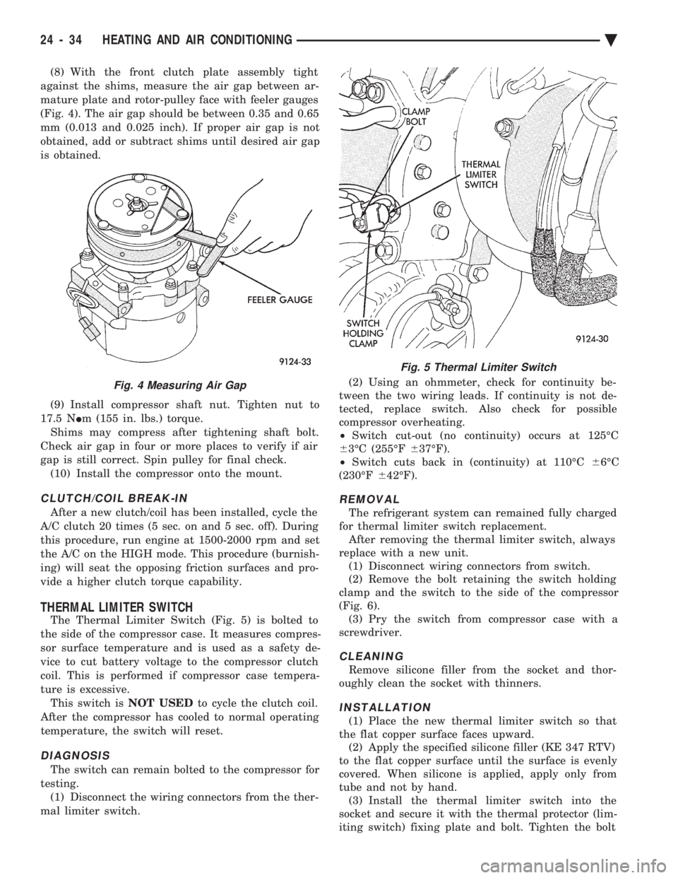
The Thermal Limiter Switch (Fig. 5) is bolted to
the side of the compressor case. It measures compres-
sor surface temperature and is used as a safety de-
vice to cut battery voltage to the compressor clutch
coil. This is performed if compressor case tempera-
ture is excessive. This switch is NOT USEDto cycle the clutch coil.
After the compressor has cooled to normal operating
temperature, the switch will reset.
DIAGNOSIS
The switch can remain bolted to the compressor for
testing. (1) Disconnect the wiring connectors from the ther-
mal limiter switch. (2) Using an ohmmeter, check for continuity be-
tween the two wiring leads. If continuity is not de-
tected, replace switch. Also check for possible
compressor overheating.
² Switch cut-out (no continuity) occurs at 125ÉC
6 3ÉC (255ÉF 637ÉF).
² Switch cuts back in (continuity) at 110ÉC 66ÉC
(230ÉF 642ÉF).
REMOVAL
The refrigerant system can remained fully charged
for thermal limiter switch replacement. After removing the thermal limiter switch, always
replace with a new unit. (1) Disconnect wiring connectors from switch.
(2) Remove the bolt retaining the switch holding
clamp and the switch to the side of the compressor
(Fig. 6). (3) Pry the switch from compressor case with a
screwdriver.
CLEANING
Remove silicone filler from the socket and thor-
oughly clean the socket with thinners.
INSTALLATION
(1) Place the new thermal limiter switch so that
the flat copper surface faces upward. (2) Apply the specified silicone filler (KE 347 RTV)
to the flat copper surface until the surface is evenly
covered. When silicone is applied, apply only from
tube and not by hand. (3) Install the thermal limiter switch into the
socket and secure it with the thermal protector (lim-
iting switch) fixing plate and bolt. Tighten the bolt
Fig. 4 Measuring Air Gap
Fig. 5 Thermal Limiter Switch
24 - 34 HEATING AND AIR CONDITIONING Ä