1993 CHEVROLET PLYMOUTH ACCLAIM run flat
[x] Cancel search: run flatPage 684 of 2438
FRONT IMPACT SENSORS
The driver air bag system is a safety device de-
signed to reduce the risk of fatality or serious injury,
caused by a frontal impact of the vehicle. The impact sensors provide verification of the di-
rection and severity of the impact. Three impact sen-
sors are used. One is called a safing sensor. It is
located inside the diagnostic module which is
mounted on the floor pan, just forward of the center
console. The other two sensors are mounted on the
upper crossmember of the radiator closure panel on
the left and right side of the vehicle under the hood. The impact sensors are threshold sensitive switches
that complete an electrical circuit when an impact
provides a sufficient G force to close the switch. The
sensors are calibrated for the specific vehicle and re-
act to the severity and direction of the impact.
CLOCKSPRING
The clockspring is mounted on the steering column
behind the steering wheel, and is used to maintain a
continuous electrical circuit between the wiring har-
ness and the driver's air bag module. This assembly
consists of a flat ribbon-like electrically conductive
tape which winds and unwinds with the steering
wheel rotation.
DIAGNOSTIC MODULE
The Air Bag System Diagnostic Module (ASDM)
contains the safing sensor and energy reserve capac-
itor. The ASDM monitors the system to determine
the system readiness. The ASDM will store sufficient
energy to deploy the air bag for only two minutes af-
ter the battery is disconnected. If both front impact
sensors are open the air bag could be deployed up to
9.5 minutes after the battery is disconnected. The
ASDM contains on-board diagnostics, and will illumi-
nate the AIR BAG warning lamp in the cluster when
a fault occurs.
STORAGE
The air bag module must be stored in its original
special container until used for service. Additionally,
it must be stored in a clean, dry environment, away
from sources of extreme heat, sparks, and sources of
high electrical energy. Always place or store the
module on a surface with the trim cover facing up to
minimize movement in case of accidental deploy-
ment.
HANDLING LIVE MODULE
At no time should any source of electricity be per-
mitted near the inflator on the back of the module.
When carrying a live module, the trim cover should
be pointed away from the body to minimize injury in
the event of accidental deployment. In addition, if
the module is placed on a bench or other surface, the plastic trim cover should be face up to minimize
movement in case of accidental deployment. When handling a steering column with an air bag
module attached, never place the column on the floor
or other surface with the steering wheel or module
face down.
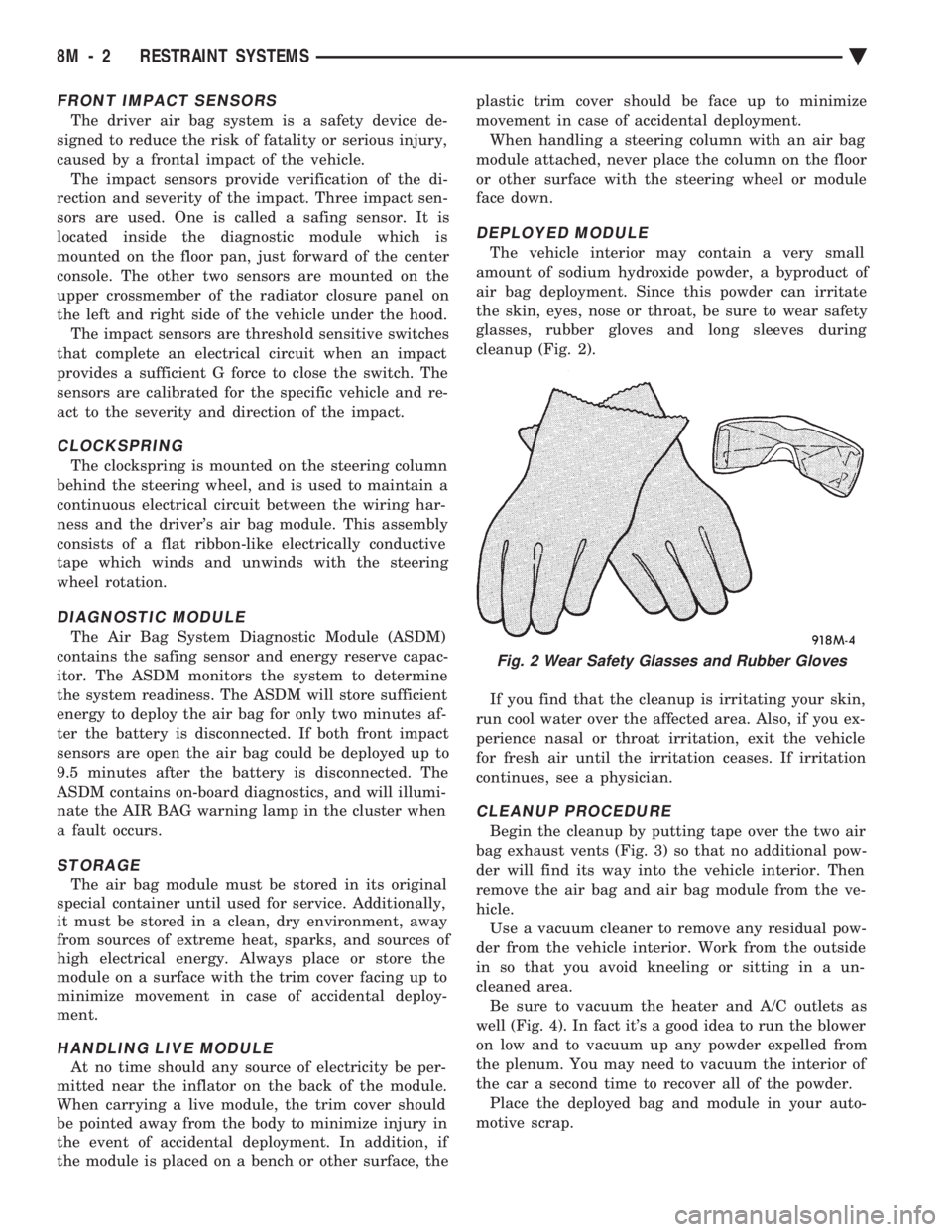
DEPLOYED MODULE
The vehicle interior may contain a very small
amount of sodium hydroxide powder, a byproduct of
air bag deployment. Since this powder can irritate
the skin, eyes, nose or throat, be sure to wear safety
glasses, rubber gloves and long sleeves during
cleanup (Fig. 2).
If you find that the cleanup is irritating your skin,
run cool water over the affected area. Also, if you ex-
perience nasal or throat irritation, exit the vehicle
for fresh air until the irritation ceases. If irritation
continues, see a physician.
CLEANUP PROCEDURE
Begin the cleanup by putting tape over the two air
bag exhaust vents (Fig. 3) so that no additional pow-
der will find its way into the vehicle interior. Then
remove the air bag and air bag module from the ve-
hicle. Use a vacuum cleaner to remove any residual pow-
der from the vehicle interior. Work from the outside
in so that you avoid kneeling or sitting in a un-
cleaned area. Be sure to vacuum the heater and A/C outlets as
well (Fig. 4). In fact it's a good idea to run the blower
on low and to vacuum up any powder expelled from
the plenum. You may need to vacuum the interior of
the car a second time to recover all of the powder. Place the deployed bag and module in your auto-
motive scrap.
Fig. 2 Wear Safety Glasses and Rubber Gloves
8M - 2 RESTRAINT SYSTEMS Ä
Page 1570 of 2438
REMOVE ALL SHIMS BEFORE REASSEM-
BLING ENGINE ALTERNATIVE METHOD Ð With the weight of
the crankshaft being supported by a jack under the
counterweight adjacent to the bearing being checked. (3) Place a piece of Plastigage across the entire
width of the bearing shell in the cap approximately
6.35 mm (1/4 inch) off center and away from the oil
holes (Fig. 2). (In addition, suspect areas can be
checked by placing the Plastigage in the suspect area).
Torque the bearing cap bolts of the bearing being
checked to the proper specifications. (4) Remove the bearing cap and compare the width
of the flattened Plastigage (Fig. 3) with the metric scale
provided on the package. Locate the band closest to the
same width. This band shows the amount of clearance
in thousandths of a millimeter. Differences in readings
between the ends indicate the amount of taper present.
Record all readings taken. Refer to Engine Specifica-
tions. Plastic-Gage generally is accompanied by
two scales. One scale is in inches, the other is a
metric scale. (5) Plastigage is available in a variety of clearance
ranges. The 0.025-0.076mm (.001-.003 inch) is usually
the most appropriate for checking engine bearing
proper specifications.
CONNECTING ROD BEARING CLEARANCE
Engine crankshaft bearing clearances can be deter-
mined by use of Plastigage or equivalent. The following
is the recommended procedure for the use of Plasti-
gage: (1) Rotate the crankshaft until the connecting rod to
be checked is at the bottom of its stroke. (2) Remove oil film from surface to be checked.
Plastigage is soluble in oil. (3) Place a piece of Plastigage across the entire
width of the bearing shell in the bearing cap approxi-
mately 6.35 mm (1/4 inch.) off center and away from
the oil hole (Fig. 2). In addition, suspect areas can be
checked by placing plastigage in the suspect area. (4) Before assembling the rod cap with Plastigage in
place, the crankshaft must be rotated until the con-
necting being checked starts moving toward the top of
the engine. Only then should the cap be assembled and
torqued to specifications. Do not rotate the crank-
shaft while assembling the cap or the Plastigage
may be smeared, giving inaccurate results. (5) Remove the bearing cap and compare the width
of the flattened Plastigage (Fig. 3) with the metric
scale provided on the package. Locate the band closest
to the same width. This band shows the amount
of clearance in thousandths of a millimeter. Differences
in readings between the ends indicate the amount
of taper present. Record all readings taken.
Refer to Engine Specifications. Plastigage generally is accompanied by two scales. One scale is in
inches, the other is a metric scale. (6) Plastigage is available in a variety of clearance
ranges. The 0.025-0.076mm (.001-.003 inch) is usually
the most appropriate for checking engine bearing
proper specifications.
LASH ADJUSTER (TAPPET) NOISE DIAGNOSIS
A tappet-like noise may be produced from several
items. Check the following items. (1) Engine oil level too high or too low. This may
cause aerated oil to enter the adjusters and cause them
to be spongy. (2) Insufficient running time after rebuilding cylin-
der head. Low speed running up to 1 hour may be
required. During this time, turn engine off and let set for a few
minutes before restarting. Repeat this several times
after engine has reached normal operating tempera-
ture. (3) Low oil pressure.
(4) The oil restrictor pressed into the vertical oil
passage to the cylinder head of Balance Shaft Engines
Only is plugged with debris. (5) Air ingested into oil due to broken or cracked oil
pump pick up. (6) Worn valve guides.
(7) Rocker arm ears contacting valve spring retainer
(2.2/2.5L engines). (8) Rocker arm loose, adjuster or tappet stuck or at
maximum extension and still leaves lash in the system. (9) Faulty lash adjuster or tappet.(a) Check for sponginess while still installed in
engine. Depress part of rocker arm just over adjuster
or pushrod . Normal adjusters should feel very firm.
Spongy adjusters can be depressed to the bottomed
position easily. (b) Remove suspected lash adjuster or tappet, pry
off retainer cap or snap ring and disassemble. Do
not reuse retainer caps . Do not interchange parts
and make sure that care and cleanliness is exercised
in the handling of parts. (c) Clean out dirt and varnish with solvent.
(d) Reassemble with engine oil.
(e) Check for sponginess.
(f) If still spongy, replace with new adjuster.
REPAIR OF DAMAGED OR WORN THREADS
Damaged or worn threads (including aluminum head
spark plug threads) can be repaired. Essentially, this
repair consists of drilling out worn or damaged
threads, tapping the hole with a special Heli-Coil (or
equivalent) Tap, and installing an insert into the
tapped hole. This brings the hole back to its original
thread size.
9 - 4 ENGINE Ä
Page 1665 of 2438
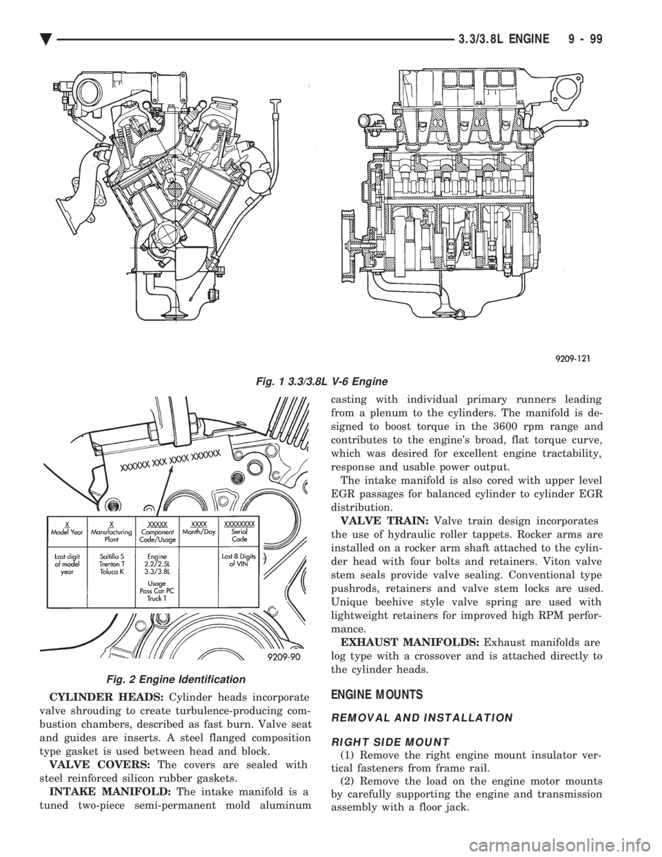
CYLINDER HEADS: Cylinder heads incorporate
valve shrouding to create turbulence-producing com-
bustion chambers, described as fast burn. Valve seat
and guides are inserts. A steel flanged composition
type gasket is used between head and block. VALVE COVERS: The covers are sealed with
steel reinforced silicon rubber gaskets. INTAKE MANIFOLD: The intake manifold is a
tuned two-piece semi-permanent mold aluminum casting with individual primary runners leading
from a plenum to the cylinders. The manifold is de-
signed to boost torque in the 3600 rpm range and
contributes to the engine's broad, flat torque curve,
which was desired for excellent engine tractability,
response and usable power output. The intake manifold is also cored with upper level
EGR passages for balanced cylinder to cylinder EGR
distribution. VALVE TRAIN: Valve train design incorporates
the use of hydraulic roller tappets. Rocker arms are
installed on a rocker arm shaft attached to the cylin-
der head with four bolts and retainers. Viton valve
stem seals provide valve sealing. Conventional type
pushrods, retainers and valve stem locks are used.
Unique beehive style valve spring are used with
lightweight retainers for improved high RPM perfor-
mance. EXHAUST MANIFOLDS: Exhaust manifolds are
log type with a crossover and is attached directly to
the cylinder heads.ENGINE MOUNTS
REMOVAL AND INSTALLATION
RIGHT SIDE MOUNT
(1) Remove the right engine mount insulator ver-
tical fasteners from frame rail. (2) Remove the load on the engine motor mounts
by carefully supporting the engine and transmission
assembly with a floor jack.
Fig. 1 3.3/3.8L V-6 Engine
Fig. 2 Engine Identification
Ä 3.3/3.8L ENGINE 9 - 99
Page 1674 of 2438
(15) Install rocker arm covers tighten screws to 14
N Im (120 in. lbs.) and connector to ignition coils.
(16) Install Intake Manifold; Refer to Intake Mani-
fold Installation 3.3/3.8L Engine, Group 11 Exhaust
System and Intake Manifold.
HYDRAULIC TAPPETS
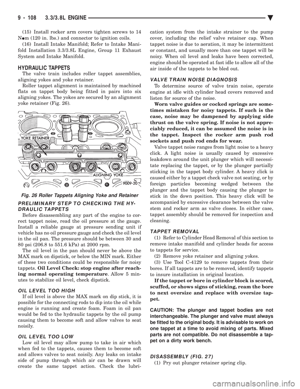
The valve train includes roller tappet assemblies,
aligning yokes and yoke retainer. Roller tappet alignment is maintained by machined
flats on tappet body being fitted in pairs into six
aligning yokes. The yokes are secured by an alignment
yoke retainer (Fig. 26).
PRELIMINARY STEP TO CHECKING THE HY- DRAULIC TAPPETS
Before disassembling any part of the engine to cor-
rect tappet noise, read the oil pressure at the gauge.
Install a reliable gauge at pressure sending unit if
vehicle has no oil pressure gauge and check the oil level
in the oil pan. The pressure should be between 30 and
80 psi (206.8 to 551.6 kPa) at 2000 rpm. The oil level in the pan should never be above the
MAX mark on dipstick, or below the MIN mark. Either
of these two conditions could be responsible for noisy
tappets. Oil Level Check: stop engine after reach-
ing normal operating temperature . Allow 5 min-
utes to stabilize oil level, check dipstick.
OIL LEVEL TOO HIGH
If oil level is above the MAX mark on dip stick, it is
possible for the connecting rods to dip into the oil while
engine is running and create foam. Foam in oil pan
would be fed to the hydraulic tappets by the oil pump
causing them to become soft and allow valves to seat
noisily.
OIL LEVEL TOO LOW
Low oil level may allow pump to take in air which
when fed to the tappets, causes them to become soft
and allows valves to seat noisily. Any leaks on intake
side of pump through which air can be drawn will
create the same tappet action. Check the lubri- cation system from the intake strainer to the pump
cover, including the relief valve retainer cap. When
tappet noise is due to aeration, it may be intermittent
or constant, and usually more than one tappet will be
noisy. When oil level and leaks have been corrected,
engine should be operated at fast idle to allow all of the
air inside of the tappets to be bled out.
VALVE TRAIN NOISE DIAGNOSIS
To determine source of valve train noise, operate
engine at idle with cylinder head covers removed and
listen for source of the noise. Worn valve guides or cocked springs are some-
times mistaken for noisy tappets. If such is the
case, noise may be dampened by applying side
thrust on the valve spring. If noise is not appre-
ciably reduced, it can be assumed the noise is in
the tappet. Inspect the rocker arm push rod
sockets and push rod ends for wear. Valve tappet noise ranges from light noise to a heavy
click. A light noise is usually caused by excessive
leakdown around the unit plunger which will necessi-
tate replacing the tappet, or by the plunger partially
sticking in the tappet body cylinder. A heavy click is
caused either by a tappet check valve not seating, or by
foreign particles becoming wedged between the
plunger and the tappet body causing the plunger to
stick in the down position. This heavy click will be
accompanied by excessive clearance between the valve
stem and rocker arm as valve closes. In either case,
tappet assembly should be removed for inspection and
cleaning.
TAPPET REMOVAL
(1) Refer to Cylinder Head Removal of this section to
remove intake manifold and cylinder heads for access
to tappets for service. (2) Remove yoke retainer and aligning yokes.
(3) Use Tool C-4129 to remove tappets from their
bores. If all tappets are to be removed, identify tappets
to insure installation in original location. If the tappet or bore in cylinder block is scored,
scuffed, or shows signs of sticking, ream the bore
to next oversize and replace with oversize tap-
pet.
CAUTION: The plunger and tappet bodies are not
interchangeable. The plunger and valve must always
be fitted to the original body. It is advisable to work on
one tappet at a time to avoid mixing of parts. Mixed
parts are not compatible. Do not disassemble a tap-
pet on a dirty work bench.
DISASSEMBLY (FIG. 27)
(1) Pry out plunger retainer spring clip.
Fig. 26 Roller Tappets Aligning Yoke and Retainer
9 - 108 3.3/3.8L ENGINE Ä
Page 1675 of 2438
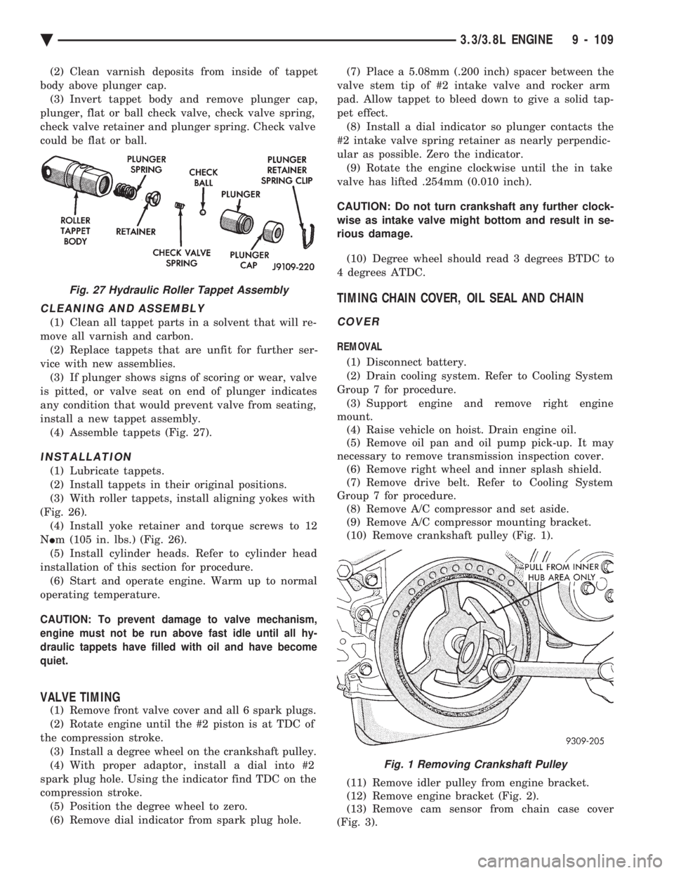
(2) Clean varnish deposits from inside of tappet
body above plunger cap. (3) Invert tappet body and remove plunger cap,
plunger, flat or ball check valve, check valve spring,
check valve retainer and plunger spring. Check valve
could be flat or ball.
CLEANING AND ASSEMBLY
(1) Clean all tappet parts in a solvent that will re-
move all varnish and carbon. (2) Replace tappets that are unfit for further ser-
vice with new assemblies. (3) If plunger shows signs of scoring or wear, valve
is pitted, or valve seat on end of plunger indicates
any condition that would prevent valve from seating,
install a new tappet assembly. (4) Assemble tappets (Fig. 27).
INSTALLATION
(1) Lubricate tappets.
(2) Install tappets in their original positions.
(3) With roller tappets, install aligning yokes with
(Fig. 26). (4) Install yoke retainer and torque screws to 12
N Im (105 in. lbs.) (Fig. 26).
(5) Install cylinder heads. Refer to cylinder head
installation of this section for procedure. (6) Start and operate engine. Warm up to normal
operating temperature.
CAUTION: To prevent damage to valve mechanism,
engine must not be run above fast idle until all hy-
draulic tappets have filled with oil and have become
quiet.
VALVE TIMING
(1) Remove front valve cover and all 6 spark plugs.
(2) Rotate engine until the #2 piston is at TDC of
the compression stroke. (3) Install a degree wheel on the crankshaft pulley.
(4) With proper adaptor, install a dial into #2
spark plug hole. Using the indicator find TDC on the
compression stroke. (5) Position the degree wheel to zero.
(6) Remove dial indicator from spark plug hole. (7) Place a 5.08mm (.200 inch) spacer between the
valve stem tip of #2 intake valve and rocker arm
pad. Allow tappet to bleed down to give a solid tap-
pet effect. (8) Install a dial indicator so plunger contacts the
#2 intake valve spring retainer as nearly perpendic-
ular as possible. Zero the indicator. (9) Rotate the engine clockwise until the in take
valve has lifted .254mm (0.010 inch).
CAUTION: Do not turn crankshaft any further clock-
wise as intake valve might bottom and result in se-
rious damage.
(10) Degree wheel should read 3 degrees BTDC to
4 degrees ATDC.
TIMING CHAIN COVER, OIL SEAL AND CHAIN
COVER
REMOVAL
(1) Disconnect battery.
(2) Drain cooling system. Refer to Cooling System
Group 7 for procedure. (3) Support engine and remove right engine
mount. (4) Raise vehicle on hoist. Drain engine oil.
(5) Remove oil pan and oil pump pick-up. It may
necessary to remove transmission inspection cover. (6) Remove right wheel and inner splash shield.
(7) Remove drive belt. Refer to Cooling System
Group 7 for procedure. (8) Remove A/C compressor and set aside.
(9) Remove A/C compressor mounting bracket.
(10) Remove crankshaft pulley (Fig. 1).
(11) Remove idler pulley from engine bracket.
(12) Remove engine bracket (Fig. 2).
(13) Remove cam sensor from chain case cover
(Fig. 3).
Fig. 27 Hydraulic Roller Tappet Assembly
Fig. 1 Removing Crankshaft Pulley
Ä 3.3/3.8L ENGINE 9 - 109
Page 1703 of 2438
CLEANING AND INSPECTION
(1) Discard gaskets and clean all gasket surfaces
on both manifolds and on cylinder head. (2) Test gasket surfaces of manifolds for flatness
with a straight edge. Surfaces must be flat within
0.15mm per 300mm (.006 in. per foot) of manifold
length. (3) Inspect manifolds for cracks and distortion.
INSTALLATION
(1) Install a new intake and exhaust manifold gas-
ket. Coat steel gasket lightly with Gasket Sealer on
manifold side. Do notcoat composition gasket with
(any) sealer. (2) Set exhaust manifold in place. Tighten retain-
ing nuts starting at center and progressing outward
in both directions to 23 N Im (200 in. lbs.) torque. Re-
peat this procedure until all nuts are at specified
torque. (3) Set intake manifold in place.
(4) Raise vehicle and tighten retaining screws
starting at center and progressing outward in both
directions to 23 N Im (200 in. lbs.) torque (Fig. 3). Re-
peat this procedure until all screws are at specified
torque. (5) Reverse removal procedures 1-9 for installation.
(6) With the DRBII Scan Tool use ASD Fuel Sys-
tem Test to pressurize system to check for leaks.
CAUTION: When using the ASD Fuel System Test,
the Auto Shutdown (ASD) relay will remain ener-
gized for 7 minutes or until the ignition switch is
turned to the OFF position, or Stop All Test is se-
lected.
INTAKE AND EXHAUST MANIFOLDSÐFLEXIBLE
FUEL ENGINE
INTAKE MANIFOLD
The manifold is die-cast aluminum with upper ple-
num and 4 tubes lower runners. These attach to the
cylinder head, with each runner leading directly to a
cylinder. The manifold is also machined for fuel rail attach-
ment and injector installation. The throttle body is
installed on the upper plenum of the manifold.
EXHAUST MANIFOLD
All high strength iron casting that intermesh with
the intake manifold. For standard engines a four
branch design collects and directs exhaust gases to
the conical (articulated joint connection) outlet.
INTAKE/EXHAUST MANIFOLDS
SERVICEÐFLEXIBLE FUEL ENGINES
Intake and exhaust manifolds use a one piece gas-
ket. Service procedures requiring removal and instal-
lation of either must include both manifolds.
SERVICE PRECAUTIONS
Methanol is more toxic than gasoline. Always re-
lease fuel system pressure before servicing fuel sys-
tem components and wear methanol resistant gloves
and eye protection. Avoid breathing methanol vapors or ingesting
methanol. Headaches, dizziness and even uncon-
sciousness could result from breathing these vapors.
Serious injury, blindness and even death could result
from ingesting methanol. Methanol vapors are extremely flammable and can
travel along the ground. Service vehicles in well ven-
tilated areas and avoid ignition sources. Never
smoke while servicing the vehicle. Do not allow methanol to contact skin. Prolonged
contact with methanol can cause dry skin or an al-
lergic skin reaction. Also, prolonged contact could re-
sult in absorption through the skin.
FUEL SYSTEM PRESSURE RELEASE PROCEDURE
WARNING: RELEASE FUEL SYSTEM PRESSURE
BEFORE SERVICING FUEL SYSTEM COMPONENTS.
WEAR METHANOL RESISTANT GLOVES AND EYE
PROTECTION WHILE SERVICING THE FUEL SYS-
TEM.
(a) Disconnect negative cable from battery.
(b) Remove fuel filler cap.
(c) Remove the protective cap from the fuel pres-
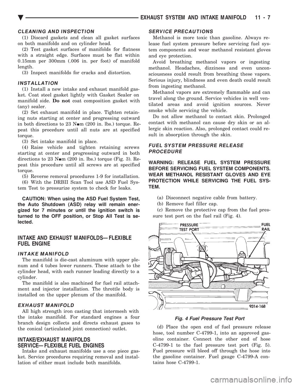
sure test port on the fuel rail (Fig. 4).
(d) Place the open end of fuel pressure release
hose, tool number C-4799-1, into an approved gas-
oline container. Connect the other end of hose
C-4799-1 to the fuel pressure test port (Fig. 5).
Fuel pressure will bleed off through the hose into
the gasoline container. Fuel gauge C-4799-A con-
tains hose C-4799-1.
Fig. 4 Fuel Pressure Test Port
Ä EXHAUST SYSTEM AND INTAKE MANIFOLD 11 - 7
Page 1856 of 2438
terrupted. This creates an alternating voltage in
each photo diode which is converted into on-off
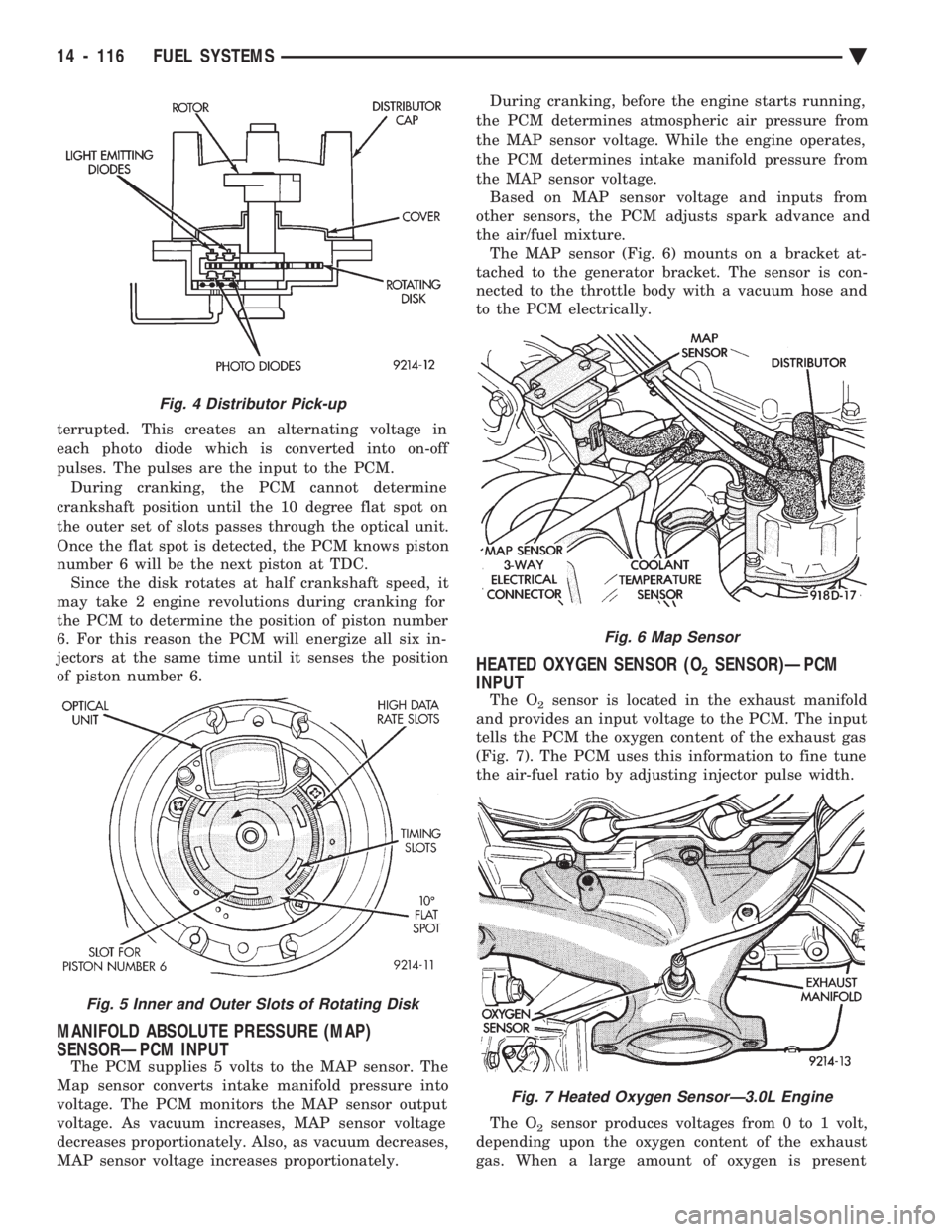
pulses. The pulses are the input to the PCM. During cranking, the PCM cannot determine
crankshaft position until the 10 degree flat spot on
the outer set of slots passes through the optical unit.
Once the flat spot is detected, the PCM knows piston
number 6 will be the next piston at TDC. Since the disk rotates at half crankshaft speed, it
may take 2 engine revolutions during cranking for
the PCM to determine the position of piston number
6. For this reason the PCM will energize all six in-
jectors at the same time until it senses the position
of piston number 6.
MANIFOLD ABSOLUTE PRESSURE (MAP)
SENSORÐPCM INPUT
The PCM supplies 5 volts to the MAP sensor. The
Map sensor converts intake manifold pressure into
voltage. The PCM monitors the MAP sensor output
voltage. As vacuum increases, MAP sensor voltage
decreases proportionately. Also, as vacuum decreases,
MAP sensor voltage increases proportionately. During cranking, before the engine starts running,
the PCM determines atmospheric air pressure from
the MAP sensor voltage. While the engine operates,
the PCM determines intake manifold pressure from
the MAP sensor voltage. Based on MAP sensor voltage and inputs from
other sensors, the PCM adjusts spark advance and
the air/fuel mixture. The MAP sensor (Fig. 6) mounts on a bracket at-
tached to the generator bracket. The sensor is con-
nected to the throttle body with a vacuum hose and
to the PCM electrically.
HEATED OXYGEN SENSOR (O2SENSOR)ÐPCM
INPUT
The O2sensor is located in the exhaust manifold
and provides an input voltage to the PCM. The input
tells the PCM the oxygen content of the exhaust gas
(Fig. 7). The PCM uses this information to fine tune
the air-fuel ratio by adjusting injector pulse width.
The O
2sensor produces voltages from 0 to 1 volt,
depending upon the oxygen content of the exhaust
gas. When a large amount of oxygen is present
Fig. 4 Distributor Pick-up
Fig. 5 Inner and Outer Slots of Rotating Disk
Fig. 6 Map Sensor
Fig. 7 Heated Oxygen SensorÐ3.0L Engine
14 - 116 FUEL SYSTEMS Ä
Page 2151 of 2438
ponents. Under extremes of suspension and steering
travel tire damage may occur.
WARNING: FAILURE TO EQUIP THE VEHICLE WITH
TIRES HAVING ADEQUATE SPEED RATING CAN
CAUSE SUDDEN TIRE FAILURE.
ROTATION
DIRECTIONAL TREAD PATTERN TIRES
Some vehicles are fitted with special high-perfor-
mance tires having a directional tread pattern de-
signed to improve traction on wet pavement. To obtain the full benefits of this design, the tires
must be installed so that they rotate in the correct
direction. This is indicated by arrows on the tire
sidewalls. When wheels and tires are being installed, extra
care is needed to ensure that this direction of rota-
tion is maintained. Refer to Owner's Manual for rotation schedule.
NONDIRECTIONAL TIRES
Tires on the front and rear axles of vehicles oper-
ate at different loads and perform different steering,
driving, and braking functions. For these reasons,
they wear at unequal rates, and tend to develop ir-
regular wear patterns. These effects can be reduced
by timely rotation of tires. Rotation will increase
tread life, help to maintain mud, snow, and wet trac-
tion levels, and contribute to a smooth, quiet ride. The suggested rotation method is the forward-cross
tire rotation method. This method takes advantage of
current tire industry practice which now allows cross
rotation of radial-ply tires. Refer to the owner's man-
ual (usually found in the glove box) for additional in-
formation. Other rotation methods may be used, but
may not have all the benefits of the recommended
method. Always check air pressure and wheel nut tightness
after rotation. Do NOT use oil or grease on studs
or nuts. Refer to Owner's Manual for rotation schedule.
TREAD WEAR INDICATORS
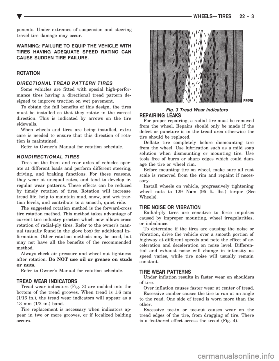
Tread wear indicators (Fig. 3) are molded into the
bottom of the tread grooves. When tread is 1.6 mm
(1/16 in.), the tread wear indicators will appear as a
13 mm (1/2 in.) band. Tire replacement is necessary when indicators ap-
pear in two or more grooves, or if localized balding
occurs.
REPAIRING LEAKS
For proper repairing, a radial tire must be removed
from the wheel. Repairs should only be made if the
defect or puncture is in the tread area otherwise the
tire should be replaced. Deflate tire completely before dismounting tire
from the wheel. Use lubrication such as a mild soap
solution when dismounting or mounting tire. Use
tools free of burrs or sharp edges which could dam-
age the tire or wheel rim. Before mounting tire on wheel, make sure all rust
scale is removed from the rim and repaint if neces-
sary. Install wheels on vehicle, progressively tightening
wheel nuts to 129 N Im (95 ft. lbs.) torque (See
Wheels).
TIRE NOISE OR VIBRATION
Radial-ply tires are sensitive to force impulses
caused by improper mounting, wheel irregularities,
or imbalance. To determine if the tires are causing the noise or
vibration, drive the vehicle over a smooth portion of
highway at different speeds and note the effect of ac-
celeration and deceleration on noise level. Differen-
tial and exhaust noise will change in intensity as
speed varies, while tire noise will usually remain
constant.
TIRE WEAR PATTERNS
Under inflation results in faster wear on shoulders
of tire. Over inflation causes faster wear at center of tread.
Excessive camber causes the tire to run at an angle
to the road. One side of tread is worn more than the
other. Excessive toe-in or toe-out causes wear on the
tread edges of the tire, from dragging of tire. There
is a feathered effect across the tread (Fig. 4).
Fig. 3 Tread Wear Indicators
Ä WHEELSÐTIRES 22 - 3