1993 CHEVROLET PLYMOUTH ACCLAIM clock
[x] Cancel search: clockPage 107 of 2438

mount have been loosened for any reason, or if vehicle
has experienced front structural damage, driveshaft
lengths must be checked and corrected, if required. A
shorter than required driveshaft length can result in ob-
jectionable noise. A longer than required driveshaft
length may result in potential damage.
Use of the following procedure will ensure satisfac-
tory driveshaft engagement under all normal vehicle
operating conditions. (1) The vehicle must be completely assembled.
Front wheels must be properly aligned and in the
straight ahead position. The vehicle must be in a po-
sition so that the full weight of the body is distrib-
uted to all four tires. A platform hoist, or front end
alignment rack, is recommended.
(2) Using a tape measure or other suitable measuring
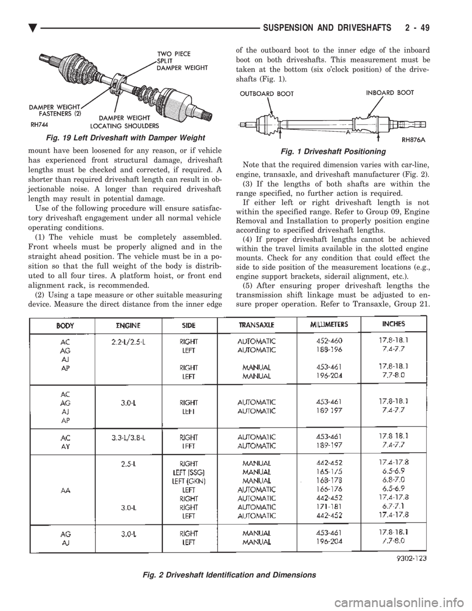
device. Measure the direct distance from the inner edge of the outboard boot to the inner edge of the inboard
boot on both driveshafts. This measurement must be
taken at the bottom (six o'clock position) of the drive-
shafts (Fig. 1).
Note that the required dimension varies with car-line,
engine, transaxle, and driveshaft manufacturer (Fig. 2).
(3) If the lengths of both shafts are within the
range specified, no further action is required. If either left or right driveshaft length is not
within the specified range. Refer to Group 09, Engine
Removal and Installation to properly position engine
according to specified driveshaft lengths.
(4) If proper driveshaft lengths cannot be achieved
within the travel limits available in the slotted engine
mounts. Check for any condition that could effect the
side to side position of the measurement locations (e.g.,
engine support brackets, siderail alignment, etc.).
(5) After ensuring proper driveshaft lengths the
transmission shift linkage must be adjusted to en-
sure proper operation. Refer to Transaxle, Group 21.
Fig. 2 Driveshaft Identification and Dimensions
Fig. 19 Left Driveshaft with Damper Weight
Fig. 1 Driveshaft Positioning
Ä SUSPENSION AND DRIVESHAFTS 2 - 49
Page 211 of 2438

WARNING: THE SELF ADJUSTING FEATURE OF THIS
PARKING BRAKE LEVER ASSEMBLY CONTAINS A
CLOCK SPRING LOADED TO APPROXIMATELY 30
POUNDS. CARE MUST BE TAKEN TO PREVENT EX-
CESSIVE JARRING OF THE ASSEMBLY. DO NOT
RELEASE THE SELF ADJUSTER LOCKOUT DEVICE
BEFORE INSTALLING CABLES INTO THE EQUAL-
IZER. KEEP HANDS OUT OF SELF ADJUSTER SEC-
TOR AND PAWL AREA. FAILURE TO OBSERVE CAU-
TION IN HANDLING THIS MECHANISM COULD LEAD
TO SERIOUS INJURY.
When repairs to the hand lever assembly or cable
system are required the self adjuster must be reloaded
and locked out.
SELF ADJUSTING PROCEDURES (AG & AJ BODY)
TO RELOAD SELF ADJUSTER
(1) Remove ash receiver or courtesy light from rear
of center console to gain access to self adjuster. Also,
remove carpet from sides of console. (2) Pull on equalizer/output cable to wind up sprin-
g(requires greater than 30 pounds effort). Continue
until self adjuster lockout pawl is positioned about
midway on the self adjuster sector (Fig. 6). Rotate
lockout pawl into self adjuster sector by turning allen
screw clockwise. Rotating lockout device requires
very little effort. Do not force or failure of lock-
out device will occur. (3) When repairs are complete, adjust rear brakes
before adjusting parking brake. On drum-in-hat type of
rear disc brake adjust shoe diameter to 171.5 mm (6.75
inch).
ADJUST PARKING BRAKE (AG & AJ BODY)
Be sure that the cables are properly assembled to the
equalizer bracket prior to cable adjustment. (1) Insert a 7/32 inch allen wrench into hex socket
and turn counter-clockwise through approximately 15É
of rotation (Fig. 4). In turning lockout device, self
adjuster release is a loud snapping noise followed by
reaching a more felt than heard detent. Very light
effort is required to seat lockout arm into detent.
Follow through to the detent is important in prevent-
ing the lockout rod from rattling. Note: The parking brake handle can be in any
position when releasing self adjuster. (2) Cycle lever to position cables. Rear wheels should
rotate freely without dragging.
REAR PARKING BRAKE CABLE REMOVAL (AA, AC,
AP, AY BODY)
The rear brake cables are attached to rear connec-
tors. Should it become necessary to remove either parking
brake cable for installation of a new cable, proceed as
follows: With vehicle jacked up on a suitable hoist, remove
wheel and tire assembly (Fig. 6). Back off cable adjusting nut to provide slack and
disconnect rear brake cable from connector.
DRUM BRAKES
(1) Disconnect park brake cable from park brake
lever in rear wheel brakes. (2) Using an aircraft type hose clamp compress re-
tainers on end of cable housing and start cable out of
retaining hole in the support plate. Remove clamp
when retainers are free of the mounting hole in the
support plate, (Fig. 6).
(3) Remove clip from brake cable at support
bracket and pull cable away from trailing arm as-
sembly (Figs. 3 and 4).
DISC BRAKES
(1) Remove disc brake caliper from adapter, and
brake disc (rotor) from rear hub.
Fig. 5 Self Adjusting Parking Brake Lever Assembly
Fig. 6 Removing Brake Cable from Support Plate
Ä BRAKES 5 - 61
Page 338 of 2438

(3) Clean the flywheel face with medium sandpa-
per (80-160 grade), then wipe the surface with min-
eral spirits. If the surface is severely scored, heat
checked, or warped, replace the flywheel.
CAUTION: Do not flat-machine the flywheel face.
The surface profile is tapered.
(4) The heavy side of the flywheel is indicated by a
daub of white paint near the outside diameter. To
minimize the effects of flywheel unbalance, perform
the following installation procedure: (a) Loose assemble the flywheel to the crank-
shaft. Use new flywheel attaching bolts which have
sealant on the threads. If new bolts are not avail-
able, apply Loctite sealant to the threads of the
original bolts. This sealant is required to prevent
engine oil leakage. (b) Rotate the flywheel and crankshaft until the
daub of white paint (heavy side) is at the 12 o'clock
position. (c) Torque flywheel attaching bolts to 95 N Im(70
ft. lbs.). Use a crisscross pattern when tightening
bolts.
(5) The disc assembly should be handled without
touching the facings. Replace disc if the facings show
evidence of grease or oil soakage, or wear to within
less than .38 mm (.015 inch) of the rivet heads. The
splines on the disc hub and transaxle input shaft
should be a snug fit without signs of excessive wear.
Metallic portions of disc assembly should be dry and
clean, and not been discolored from excessive heat.
Each of the arched springs between the facings
should not be broken and all rivets should be tight. (6) Wipe the friction surface of the pressure plate
with mineral spirits. (7) Using a straight edge, check clutch cover (pres-
sure plate) for flatness. The clutch cover (pressure
plate) friction area should be slightly concave, with
the inner diameter 0.02 mm to 0.1 mm (.0008 in. to
.0039 in.) below the outer diameter. It should also be
free from discoloration, burned areas, cracks,
grooves, or ridges. (8) Using a surface plate, test cover for flatness.
All sections around attaching bolt holes should be in
contact with surface plate within .015 inch. (9) The cover should be a snug fit on flywheel dow-
els. If the clutch assembly does not meet these re-
quirements, it should be replaced.
INSTALLATION
(1) Mount clutch assembly on flywheel,being care-
ful to properly align dowels and the alignment marks
made before removal. The flywheel side of the clutch
disc is marked for proper installation. If new clutch
or flywheel is installed, align cover balance spot as
close as possible to flywheel balance orange spot. Ap-
ply pressure to the alignment tool. Center the tip of the tool into the crankshaft and the sliding cone into
the clutch fingers. Tighten the clutch attaching bolts
sufficiently to hold the disc in position. (2) To avoid distortion of the clutch cover, bolts
should be tightened a few turns at a time, in a criss-
cross pattern, until they are all seated. Tighten bolts
to 28 N Im (250 in. lbs.) following a crisscross pattern
sequence. Remove clutch disc alignment tool. (3) Install transaxle. See group 21, Manual Tran-
saxle, for procedures.
RELEASE BEARING AND FORK
Remove the transaxle from the vehicle. See group
21 for removal and installation procedures.
REMOVAL AND INSTALLATION
(1) Remove clutch release shaft E-clip.
(2) Remove the clutch release shaft and then slide
the fork and bearing assembly off the bearing pilot. (3) Remove the fork from the bearing thrust plate.
(4) Examine the condition of the bearing. It is pre-
lubricated and sealed and should not be im-
mersed in oil or solvent. (5) The bearing should turn smoothly when held in
the hand under a light thrust load. A light drag
caused by the lubricant fill is normal. If the bearing
is noisy, rough, or dry, replace the complete bearing
assembly with a new bearing. (6) The bearing has a plastic sleeve pre-lubricated
at assembly. Wipe out the old grease. Refill the
sleeve cavities and coat the inner surface with mul-
tipurpose grease. If the liner is cracked or worn, re-
place the bearing assembly. (7) Check the condition of the spring clips. If the
clips are broken or distorted, replace the bearing as-
sembly. (8) Before assembling the fork, lubricate the
rounded thrust pads and the spring clip cavities with
multipurpose grease. (9) Assemble the fork to the bearing by sliding the
thrust pads under the spring clips. Be careful to
avoid distorting the spring clips. These clips prevent
the bearing thrust plate from rotating with the bear-
ing. (10) Slide the bearing and fork assembly onto the
input shaft bearing retainer. (11) Position the release shaft bushings in the
housing and install the release shaft. A small
amount of bearing grease between the release shaft
bushing and the shaft is beneficial but not required.
Install the retainer clip in the shaft groove near the
large bushing. (12) Install the release lever and retaining clip on
the outer end of the release shaft.
CLEANING PRECAUTIONS
Condensation from steam vapors tend to accumu-
late on the internal clutch mechanism when the ve-
6 - 6 MANUAL TRANSAXLE CLUTCH Ä
Page 360 of 2438

RADIATOR PRESSURE CAP
Radiators are equipped with a pressure cap which
releases pressure at some point within a range of
97-124 kPa (14-18 psi) (Fig. 7). The system will operate at higher than atmospheric
pressure which raises the coolant boiling point allow-
ing increased radiator cooling capacity. There is also a vent valve in the center of the cap that
allows a small coolant flow to the CRS tank. If valve is
stuck shut, the radiator hoses will be collapsed
on cool down. Clean the vent valve (Fig. 7) to
ensure proper sealing when boiling point is
reached.
There is also a gasket in the cap to seal to the top of
the filler neck so that vacuum can be maintained for
drawing coolant back into the radiator from the coolant
reserve system tank.
RADIATOR CAP TO FILLER NECK SEAL PRES- SURE RELIEF CHECK
The pressure cap upper gasket (seal) pressure relief
can be checked by removing the overflow hose at the
radiator filler neck nipple (Fig. 7). Attach the Radiator
Pressure Tool to the filler neck nipple and pump air
into the radiator. Pressure cap upper gasket should
relieve at 69-124 kPa (10-18 psi) and hold pressure at
55 kPa (8 psi) minimum.
WARNING: THE WARNING WORDS DO NOT OPEN
HOT ON THE RADIATOR PRESSURE CAP IS A
SAFETY PRECAUTION. WHEN HOT, PRESSURE
BUILDS UP IN COOLING SYSTEM. TO PREVENT
SCALDING OR INJURY, THE RADIATOR CAP
SHOULD NOT BE REMOVED WHILE THE SYSTEM IS
HOT AND/OR UNDER PRESSURE.
There is no need to remove the radiator cap at any
time except for the following purposes:
(1) Check and adjust antifreeze freeze point.
(2) Refill system with new antifreeze.
(3) Conducting service procedures.
(4) Checking for vacuum leaks.
WARNING: IF VEHICLE HAS BEEN RUN RECENTLY,
WAIT 15 MINUTES BEFORE REMOVING CAP. THEN PLACE A SHOP TOWEL OVER THE CAP AND WITH-
OUT PUSHING DOWN ROTATE IT COUNTER-
CLOCKWISE TO THE FIRST STOP. ALLOW FLUIDS
TO ESCAPE THROUGH THE OVERFLOW TUBE AND
WHEN THE SYSTEM STOPS PUSHING COOLANT
AND STEAM INTO THE CRS TANK AND PRESSURE
DROPS PUSH DOWN AND REMOVE THE CAP COM-
PLETELY. SQUEEZING THE RADIATOR INLET HOSE
WITH A SHOP TOWEL (TO CHECK PRESSURE) BE-
FORE AND AFTER TURNING TO THE FIRST STOP IS
RECOMMENDED.
PRESSURE TESTING RADIATOR CAPS
Dip the pressure cap in water, clean any deposits off
the vent valve or its seat and apply cap to end of
Radiator Pressure Tool. Working the plunger, bring the
pressure to 104 kPa (15 psi) on the gauge. If the
pressure cap fails to hold pressure of at least 97 kPa
(14 psi) replace cap. See CAUTION
If the pressure cap tests properly while positioned on
Radiator Pressure Tool, but will not hold pressure or
vacuum when positioned on the radiator. Inspect the
radiator filler neck and cap top gasket for irregularities
that may prevent the cap from sealing properly.
CAUTION: Radiator Pressure Tool is very sensitive to
small air leaks which will not cause cooling system
problems. A pressure cap that does not have a
history of coolant loss should not be replaced just
because it leaks slowly when tested with this tool.
Add water to the tool. Turn tool upside down and
recheck pressure cap to confirm that cap is bad.
INSPECTION
Hold the cap in hand, right side up(Fig. 7). The
vent valve at the bottom of the cap should open. If the
rubber gasket has swollen and prevents the valve from
opening, replace the cap. Hold the cleaned cap in hand upside down.If any
light can be seen between vent valve and rubber
gasket, replace cap. Do not use a replacement cap
that has a spring to hold the vent shut. Replacement cap must be of the type designed for
coolant reserve systems. This design assures coolant
return to radiator.
RADIATORS
The radiators are crossflow types (horizontal tubes)
with design features that provide greater strength as
well as sufficient heat transfer capabilities to keep the
engine satisfactorily cooled.
CAUTION: Plastic tanks, while stronger then brass
are subject to damage by impact, such as wrenches.
Fig. 7 Radiator Pressure Cap Filler Neck
7 - 18 COOLING SYSTEM Ä
Page 361 of 2438

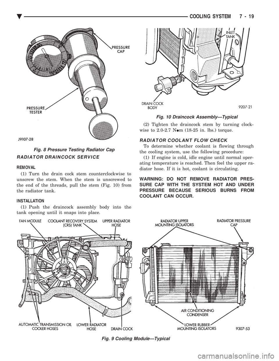
RADIATOR DRAINCOCK SERVICE
REMOVAL (1) Turn the drain cock stem counterclockwise to
unscrew the stem. When the stem is unscrewed to
the end of the threads, pull the stem (Fig. 10) from
the radiator tank.
INSTALLATION (1) Push the draincock assembly body into the
tank opening until it snaps into place. (2) Tighten the draincock stem by turning clock-
wise to 2.0-2.7 N Im (18-25 in. lbs.) torque.
RADIATOR COOLANT FLOW CHECK
To determine whether coolant is flowing through
the cooling system, use the following procedure: (1) If engine is cold, idle engine until normal oper-
ating temperature is reached. Then feel the upper ra-
diator hose. If it is hot, coolant is circulating.
WARNING: DO NOT REMOVE RADIATOR PRES-
SURE CAP WITH THE SYSTEM HOT AND UNDER
PRESSURE BECAUSE SERIOUS BURNS FROM
COOLANT CAN OCCUR.
Fig. 9 Cooling ModuleÐTypical
Fig. 8 Pressure Testing Radiator Cap
Fig. 10 Draincock AssemblyÐTypical
Ä COOLING SYSTEM 7 - 19
Page 368 of 2438

by tightening adjusting screw (Figs. 3 and 4 ).
Tighten pulley nut to 54 N Im (40 ft. lbs.) after ad-
justment.
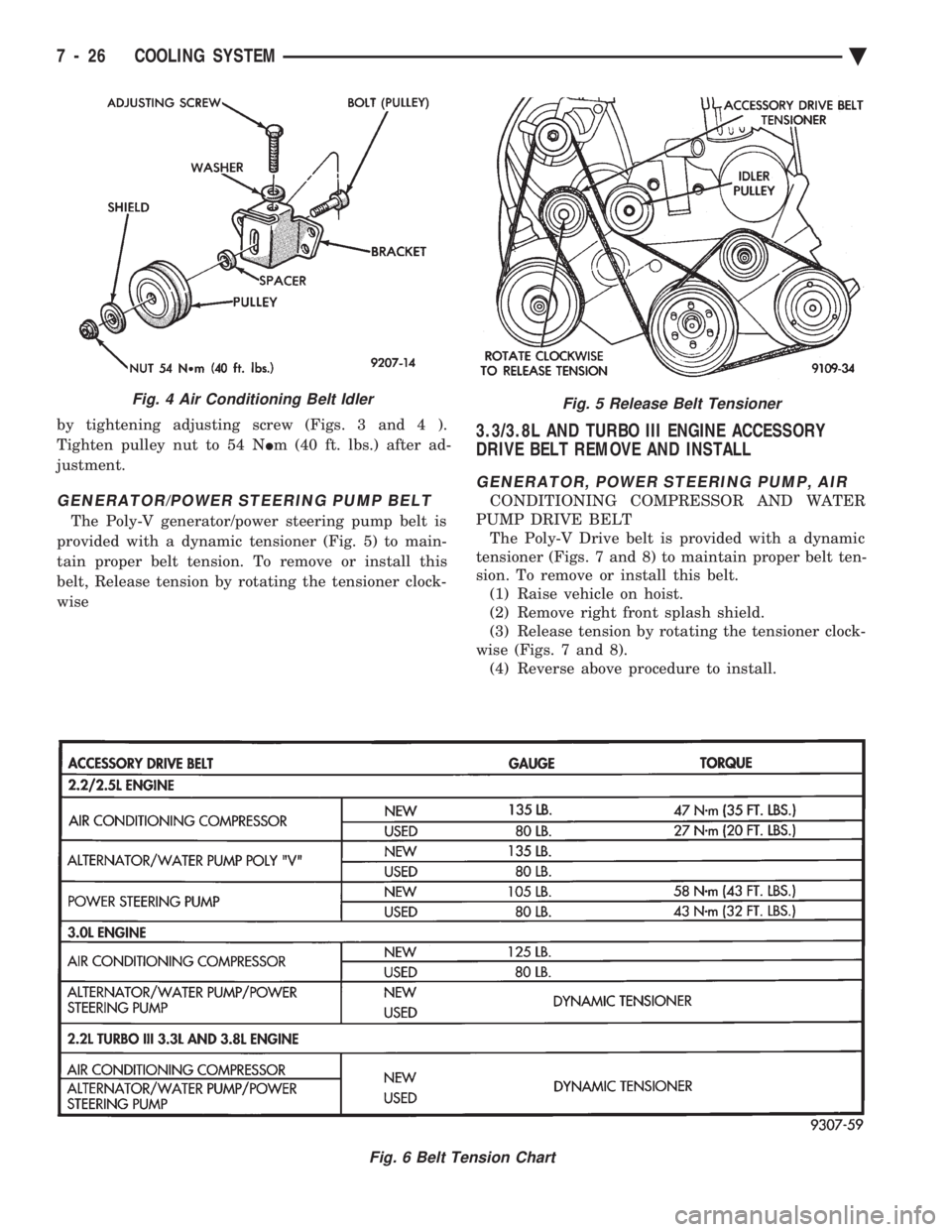
GENERATOR/POWER STEERING PUMP BELT
The Poly-V generator/power steering pump belt is
provided with a dynamic tensioner (Fig. 5) to main-
tain proper belt tension. To remove or install this
belt, Release tension by rotating the tensioner clock-
wise
3.3/3.8L AND TURBO III ENGINE ACCESSORY
DRIVE BELT REMOVE AND INSTALL
GENERATOR, POWER STEERING PUMP, AIR
CONDITIONING COMPRESSOR AND WATER
PUMP DRIVE BELT The Poly-V Drive belt is provided with a dynamic
tensioner (Figs. 7 and 8) to maintain proper belt ten-
sion. To remove or install this belt. (1) Raise vehicle on hoist.
(2) Remove right front splash shield.
(3) Release tension by rotating the tensioner clock-
wise (Figs. 7 and 8). (4) Reverse above procedure to install.
Fig. 5 Release Belt Tensioner
Fig. 6 Belt Tension Chart
Fig. 4 Air Conditioning Belt Idler
7 - 26 COOLING SYSTEM Ä
Page 382 of 2438

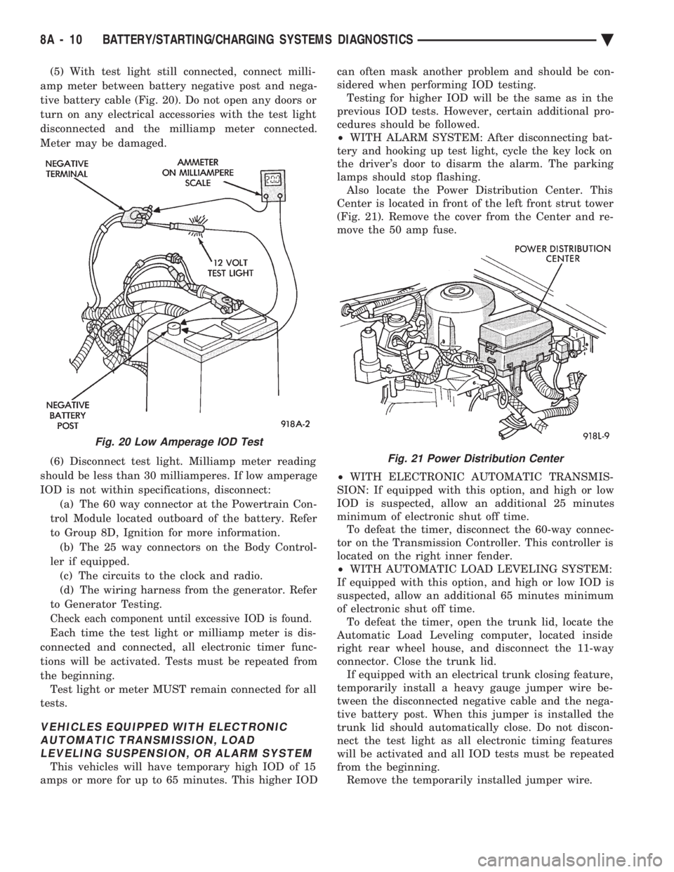
(5) With test light still connected, connect milli-
amp meter between battery negative post and nega-
tive battery cable (Fig. 20). Do not open any doors or
turn on any electrical accessories with the test light
disconnected and the milliamp meter connected.
Meter may be damaged.
(6) Disconnect test light. Milliamp meter reading
should be less than 30 milliamperes. If low amperage
IOD is not within specifications, disconnect: (a) The 60 way connector at the Powertrain Con-
trol Module located outboard of the battery. Refer
to Group 8D, Ignition for more information. (b) The 25 way connectors on the Body Control-
ler if equipped. (c) The circuits to the clock and radio.
(d) The wiring harness from the generator. Refer
to Generator Testing.
Check each component until excessive IOD is found.
Each time the test light or milliamp meter is dis-
connected and connected, all electronic timer func-
tions will be activated. Tests must be repeated from
the beginning. Test light or meter MUST remain connected for all
tests.
VEHICLES EQUIPPED WITH ELECTRONIC AUTOMATIC TRANSMISSION, LOADLEVELING SUSPENSION, OR ALARM SYSTEM
This vehicles will have temporary high IOD of 15
amps or more for up to 65 minutes. This higher IOD can often mask another problem and should be con-
sidered when performing IOD testing. Testing for higher IOD will be the same as in the
previous IOD tests. However, certain additional pro-
cedures should be followed.
² WITH ALARM SYSTEM: After disconnecting bat-
tery and hooking up test light, cycle the key lock on
the driver's door to disarm the alarm. The parking
lamps should stop flashing. Also locate the Power Distribution Center. This
Center is located in front of the left front strut tower
(Fig. 21). Remove the cover from the Center and re-
move the 50 amp fuse.
² WITH ELECTRONIC AUTOMATIC TRANSMIS-
SION: If equipped with this option, and high or low
IOD is suspected, allow an additional 25 minutes
minimum of electronic shut off time. To defeat the timer, disconnect the 60-way connec-
tor on the Transmission Controller. This controller is
located on the right inner fender.
² WITH AUTOMATIC LOAD LEVELING SYSTEM:
If equipped with this option, and high or low IOD is
suspected, allow an additional 65 minutes minimum
of electronic shut off time. To defeat the timer, open the trunk lid, locate the
Automatic Load Leveling computer, located inside
right rear wheel house, and disconnect the 11-way
connector. Close the trunk lid. If equipped with an electrical trunk closing feature,
temporarily install a heavy gauge jumper wire be-
tween the disconnected negative cable and the nega-
tive battery post. When this jumper is installed the
trunk lid should automatically close. Do not discon-
nect the test light as all electronic timing features
will be activated and all IOD tests must be repeated
from the beginning. Remove the temporarily installed jumper wire.
Fig. 20 Low Amperage IOD Test
Fig. 21 Power Distribution Center
8A - 10 BATTERY/STARTING/CHARGING SYSTEMS DIAGNOSTICS Ä
Page 417 of 2438

OVERHEAD CONSOLE
CONTENTS
page page
AA BODY .............................. 1
AC AND AY BODY ....................... 6 AG AND AJ BODIES
.................... 13
AP BODY ............................. 21
GENERAL INFORMATION AA BODY
INDEX
page page
Ambient Temperature Sensor ................ 6
Compass Calibration ....................... 2
Compass Diagnostics ...................... 5
Compass Module Replacement ............... 6
Demagnetizing Procedure ................... 4 Map Reading Lamps
....................... 1
Overhead Console Replacement .............. 5
Self-Diagnostic Test ....................... 5
Thermometer and Compass Operation ......... 1
Variance ................................ 2
MAP READING LAMPS
The map reading and rear passenger lamps are
turned on and off by pressing their individual switch
marked LAMP. These same lamps also serve as cour-
tesy lamps whenever a door is opened, the illumi-
nated entry system is activated, or the headlamp
switch is turned fully clockwise.
LAMP REPLACEMENT
(1) Remove lens by inserting a large paper clip or
wire, with a hook on the end, into the hole in the
lens and pull downward (Fig. 1).
(2) Remove lamp by pulling firmly toward front of
vehicle. (3) Install new lamp by pushing firmly into recep-
tacle. (4) Snap lens into position taking care to orient
the tabs on the lens with the slots in the housing and
snap into position.
LAMP TEST
(1) Close vehicle doors.
(2) Press each lamp switch button (Fig.2). Right
hand button should light passenger side lamp and
left hand button should light drivers side lamp front
or rear. (3) If any of the lamps fail to illuminate, open ve-
hicle doors: (a) If lamp does not illuminate check for a
burned out lamp. If lamp is OK, check fuse and
wire connectors. (b) If lamp illuminates when doors are open
check switch.
THERMOMETER AND COMPASS OPERATION
The ignition switch must be in the ON or ACCES-
SORY position before the temperature and compass
reading can be displayed. The Comp/Temp switch, lo-
cated left of the display module, turns the display on
and off. The US/Metric switch, located right of the dis-
play, changes the temperature reading from Fahrenheit
to Celsius. Should the compass blank out and the CAL
symbol only light, demagnetizing may be necessary.
The compass is a flux-gate system which, is inte-
gral to the console. The temperature readout is con-
nected to a thermistor sensor which, located on the
front lower radiator closure panel.Fig. 1 Overhead Console Lens Removal
Ä OVERHEAD CONSOLE 8C - 1