1993 CHEVROLET PLYMOUTH ACCLAIM clock
[x] Cancel search: clockPage 633 of 2438

CONDITION: WIPERS START TO WIPE, BUT STOP BEFORE ONE COMPLETE CYCLE ANDDO NOT RETURN TO PARK POSITION
PROCEDURE
(1) Verify that motor will park when the column
switch is put in the OFF position. (2) Set wiper control switch to maximum DELAY
and allow motor to run until it stops during the wipe
cycle. When motor stops, disconnect 25-way blue con-
nector from the body controller. (3) Connect positive lead of voltmeter to pin 20 of
blue connector and negative lead to the metal case of
the body controller. (a) If voltmeter reads 0, check wiring for an open
circuit. (b) If voltmeter reads 10 to 15 volts, proceed to
step 4.
(4) Using an ohmmeter or continuity tester; (a) Check for continuity between pins 20 and 24
of blue connector of the body controller. (b) Reverse ohmmeter leads on pins 20 and 24,
again checking for continuity. (c) If continuity between pins 20 and 24 is not
observed in both steps a and b, replace the body
controller.
CONDITION: EXCESSIVE DELAY OF MORE THAN 30 SECONDS OR INADEQUATEVARIATION IN DELAY
PROCEDURE
(1) Variations in delay should be as follows: (a) Minimum delay control to extreme counter-
clockwise position before first detent of 1/2 to 2 sec-
onds. (b) Maximum delay control to extreme clockwise
position before OFF detent of 15 to 25 seconds.
(2) If there is excessive delay or no variations in
delay, remove the wiper motor wiring harness while
the motor is parked in the OFF position. (3) Remove 25-way blue connector from the body
controller. (4) Set wiper control switch to maximum DELAY
position. (5) With ignition switch in ON position, measure
voltage between pin 9 of black connector and a good
ground. (a) If voltmeter reads 0, proceed to step 6.
(b) If voltmeter reads 10 to 15 volts, proceed to
step 7.
(6) Set wiper control switch to minimum DELAY
position and measure voltage between pin 9 of blue
connector and a good ground. If voltmeter reads 0,
check for an open circuit in the intermittent wipe
wiring harness. (7) Remove wiper motor circuit fuse. (8) Using an ohmmeter, measure the resistance be-
tween pins 9 and 22 of the body controller 25-way
black connector. Set the wiper control switch first to
minimum DELAY and then maximum DELAY. (a) If resistance reading at minimum DELAY
setting is between 0 and 15 ohms, and at maxi-
mum DELAY setting the resistance is between
240,000 and 400,000 ohms, replace the body con-
troller. (b) If the resistance values above are not ob-
tained, replace the wiper control switch.
CONDITION: WIPERS DO NOT RUN CONTINUALLY WHEN WASH CONTROL ISOPERATED DURING DELAY MODE
PROCEDURE
(1) Disconnect 25-way blue connector from the
body controller (2) Using a voltmeter, connect the positive lead to
pin 10 of the (Black) connector. Connect negative
lead to the body computer metal case. (3) Set wiper control switch to DELAY position.
(4) Depress wash switch.
(5) If voltage reads 0, check switch relay and wir-
ing. (6) If voltage is between 10 and 15 volts, the prob-
lem is in the body controller.
CONDITION: IN DELAY MODE, WIPERS RUN CONTINUALLY WHEN WASH IS OPERATEDBUT DO NOT PROVIDE FOUR EXTRA WIPESWHEN WASH CONTROL IS RELEASED
PROCEDURE
Replace body controller.
CONDITION: WIPERS START ERRATICALLY DURING DELAY MODE
PROCEDURE
(1) Verify that the ground connection at the in-
strument panel is making a good connection, free
from paint and is tight. (2) Verify that the motor ground strap is making
good contact and that the motor mounting bolts are
tight. (3) Verify that the wiring connections to the body
controller, wiper motor, and wiper motor switch are
tight and free of corrosion. (4) If condition is not corrected, problem is with
the body controller
Ä WINDSHIELD WIPER AND WASHER SYSTEMS 8K - 13
Page 634 of 2438

INTERMITTENT WIPER FUNCTION TESTS
CONDITION: EXCESSIVE DELAY OF MORE THAN 30 SECONDS OR INADEQUATEVARIATION IN DELAY
PROCEDURE
Variations in delay should be as follows:
(1) Minimum delay control to extreme counter-
clockwise position before first detent of one half to
two seconds. (2) Maximum delay control to extreme clockwise
position before off detent of ten to thirty seconds. (3) If there is excessive delay or no variations in
delay proceed to intermittent wipe switch test.
CONDITION: IN DELAY MODE WIPERS RUN CONTINUALLY WHEN WASH IS OPERATEDBUT DO NOT PROVIDE AN EXTRA WIPEWHEN THE WASH CONTROL IS RELEASED
PROCEDURE
Replace the control unit.
CONDITION: WIPERS START ERRATICALLY DURING DELAY MODE
PROCEDURE
(1) Verify that the ground connection at the in-
strument panel is making good connection, free from
paint and is tight. (2) Verify that the motor ground strap is making
good contact and that the motor mounting bolts are
tight. (3) Verify that the wiring ground connections for
the intermittent wipe control unit and the wiper
switch are tight. (4) If condition is not corrected, replace control
unit.
STANDARD WIPER SWITCH TEST
AP BODY
To test the switch, first disconnect the switch wires
from the body wiring in the steering column. Using
an ohmmeter, test for continuity between the termi-
nals of the switch, as indicated in the following con-
tinuity chart. The identity of each terminal is shown
in Fig. 23.
INTERMITTENT WIPE SWITCH TEST
AC AND AY BODIES
To test the switch, first disconnect the switch wires
from the body wiring in the steering column. Using
an ohmmeter, test for continuity between the termi-
nals of the switch, as indicated in the following con-
tinuity chart. The identity of each terminal is shown
in Fig. 24. For test purposes, the first position is the OFF po-
sition, next is the slide for the DELAY wipe. LOW is
the next detent position and HIGH is the full coun-
terclockwise detent position. In any wiper mode, if the knob is pushed all the
way in, the washer circuit will be completed.
AG AND AJ BODIES
To test the switch, remove switch pod from instru-
ment panel. Using an ohmmeter, test for continuity
between the terminals of the switch, as indicated in
the following continuity chart (Fig. 25).
Fig. 23 Standard 2-Speed Wiper Switch Test
Fig. 24 Multi-Function Switch Connector and Intermittent Wipe Continuity
8K - 14 WINDSHIELD WIPER AND WASHER SYSTEMS Ä
Page 649 of 2438
EXTERIOR LAMPSÐAA BODY INDEX
page page
Center High-Mounted Stop Lamp (CHMSL) Bulb . . 9
Fog Lamp ............................... 9
Fog Lamp Bulb ........................... 9
Front Side Marker Lamp or Bulb .............. 7
Headlamp Bulb ........................... 7 Headlamp Lens
........................... 7
License Plate Lamp or BulbÐAA/P Body ....... 8
License Plate LampsÐAA/C Body ............. 8
Park and Turn Signal Lamp or Bulb ........... 7
Tail, Stop and Turn Signal and Back-Up Lamp . . . 8
HEADLAMP BULB
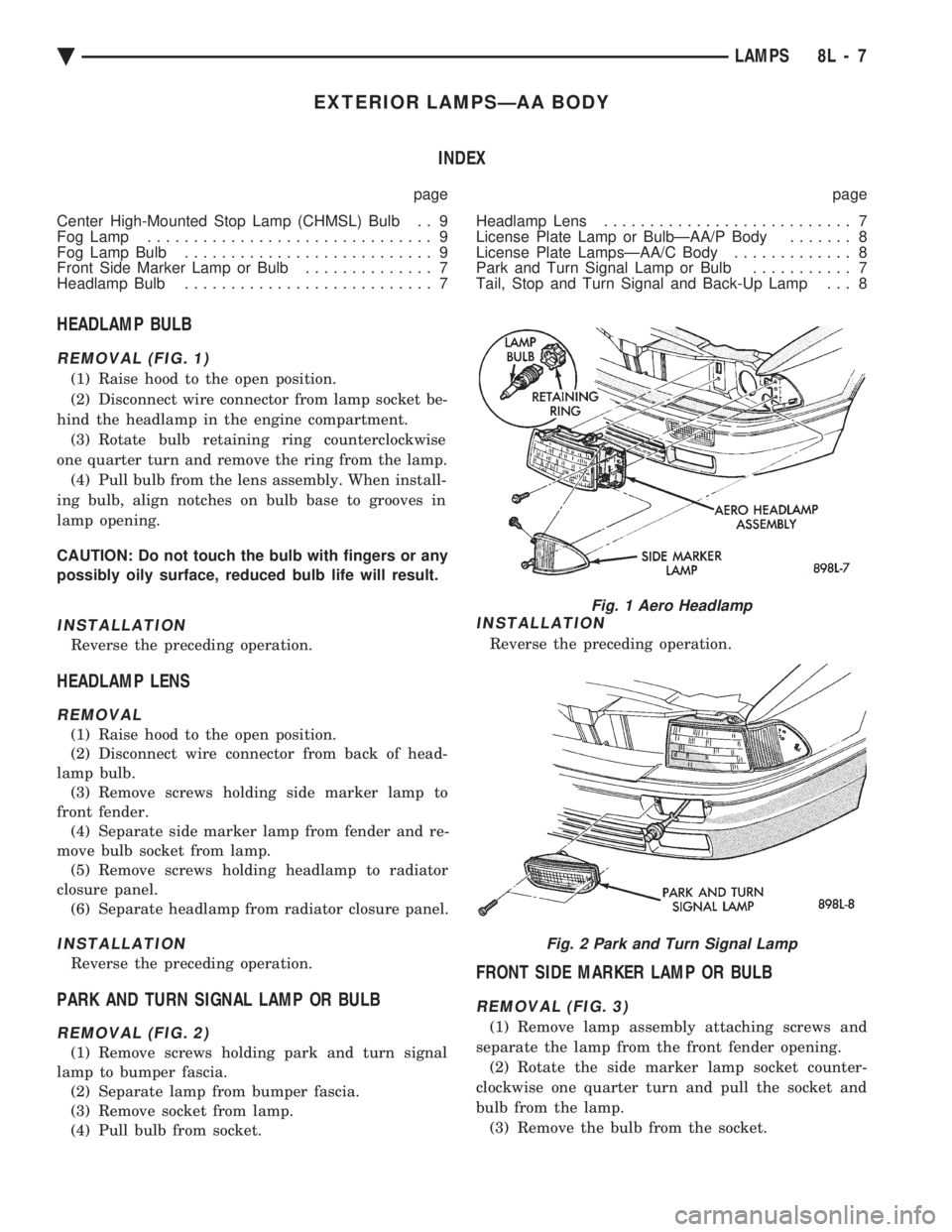
REMOVAL (FIG. 1)
(1) Raise hood to the open position.
(2) Disconnect wire connector from lamp socket be-
hind the headlamp in the engine compartment. (3) Rotate bulb retaining ring counterclockwise
one quarter turn and remove the ring from the lamp. (4) Pull bulb from the lens assembly. When install-
ing bulb, align notches on bulb base to grooves in
lamp opening.
CAUTION: Do not touch the bulb with fingers or any
possibly oily surface, reduced bulb life will result.
INSTALLATION
Reverse the preceding operation.
HEADLAMP LENS
REMOVAL
(1) Raise hood to the open position.
(2) Disconnect wire connector from back of head-
lamp bulb. (3) Remove screws holding side marker lamp to
front fender. (4) Separate side marker lamp from fender and re-
move bulb socket from lamp. (5) Remove screws holding headlamp to radiator
closure panel. (6) Separate headlamp from radiator closure panel.
INSTALLATION
Reverse the preceding operation.
PARK AND TURN SIGNAL LAMP OR BULB
REMOVAL (FIG. 2)
(1) Remove screws holding park and turn signal
lamp to bumper fascia. (2) Separate lamp from bumper fascia.
(3) Remove socket from lamp.
(4) Pull bulb from socket.
INSTALLATION
Reverse the preceding operation.
FRONT SIDE MARKER LAMP OR BULB
REMOVAL (FIG. 3)
(1) Remove lamp assembly attaching screws and
separate the lamp from the front fender opening. (2) Rotate the side marker lamp socket counter-
clockwise one quarter turn and pull the socket and
bulb from the lamp. (3) Remove the bulb from the socket.
Fig. 1 Aero Headlamp
Fig. 2 Park and Turn Signal Lamp
Ä LAMPS 8L - 7
Page 651 of 2438
CENTER HIGH-MOUNTED STOP LAMP (CHMSL)
BULB
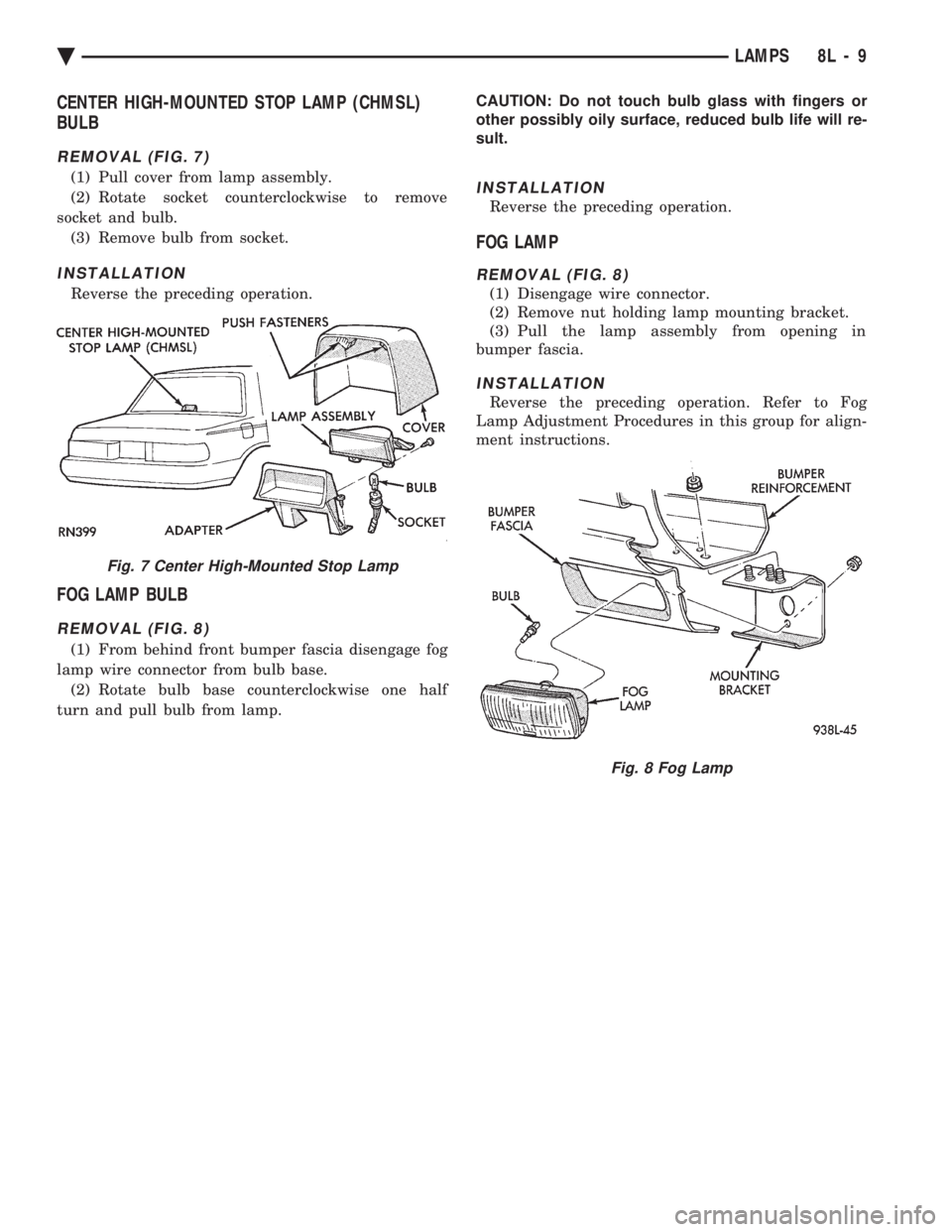
REMOVAL (FIG. 7)
(1) Pull cover from lamp assembly.
(2) Rotate socket counterclockwise to remove
socket and bulb. (3) Remove bulb from socket.
INSTALLATION
Reverse the preceding operation.
FOG LAMP BULB
REMOVAL (FIG. 8)
(1) From behind front bumper fascia disengage fog
lamp wire connector from bulb base. (2) Rotate bulb base counterclockwise one half
turn and pull bulb from lamp. CAUTION: Do not touch bulb glass with fingers or
other possibly oily surface, reduced bulb life will re-
sult.
INSTALLATION
Reverse the preceding operation.
FOG LAMP
REMOVAL (FIG. 8)
(1) Disengage wire connector.
(2) Remove nut holding lamp mounting bracket.
(3) Pull the lamp assembly from opening in
bumper fascia.
INSTALLATION
Reverse the preceding operation. Refer to Fog
Lamp Adjustment Procedures in this group for align-
ment instructions.
Fig. 7 Center High-Mounted Stop Lamp
Fig. 8 Fog Lamp
Ä LAMPS 8L - 9
Page 652 of 2438
EXTERIOR LAMPSÐAC BODY INDEX
page page
Aero Headlamp Bulb ...................... 10
Aero Headlamp Housing ................... 11
Aero HeadlampsÐAC/D-Body ............... 10
Center High Mounted Stop Lamp (CHMSL) ..... 13
Center High-Mounted Stop Lamp (CHMSL) Bulb . 13
Cornering Lamp Assembly .................. 12
Cornering Lamp Bulb ..................... 12
Front Side Marker BulbÐAC/C-Body .......... 12
Front Side Marker LampÐAC/C-Body ......... 12
Headlamp Diagnosis ...................... 10 Headlamp Sealed BeamÐAC/C Body
......... 10
License Plate Lamp/Bulb ................... 13
Park/Turn Signal Lamp or BulbÐAC/C-Body .... 11
Park/Turn Signal Lamp or BulbÐAC/D-Body .... 11
Rear Side Marker Lamp BulbÐAC/C-Body ..... 13
Rear Side Marker LampÐAC/C-Body ......... 13
Tail, Stop, Turn Signal, Back-Up and Side Marker LampÐAC/D-Body ...................... 12
Tail, Stop, Turn Signal, Back-Up LampÐAC/C or AY/S-Body ............................ 12
HEADLAMP DIAGNOSIS
Refer to the Headlamp Diagnosis at the beginning of
this Group. Refer to Wiring Diagrams Manual for
circuit and component locations.
HEADLAMP SEALED BEAMÐAC/C BODY
REMOVAL
(1) Turn the headlight switch ON.
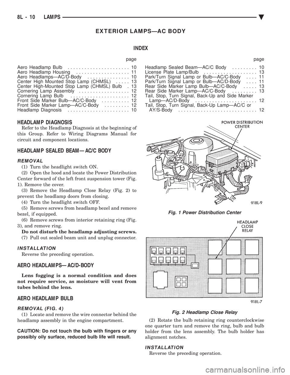
(2) Open the hood and locate the Power Distribution
Center forward of the left front suspension tower (Fig.
1). Remove the cover. (3) Remove the Headlamp Close Relay (Fig. 2) to
prevent the headlamp doors from closing. (4) Turn the headlight switch OFF.
(5) Remove screws from headlamp bezel and remove
bezel, if equipped. (6) Remove screws from interior retaining ring (Fig.
3), and remove ring. Do not disturb the headlamp adjusting screws.
(7) Pull out sealed beam unit and unplug connector.
INSTALLATION
Reverse the preceding operation.
AERO HEADLAMPSÐAC/D-BODY
Lens fogging is a normal condition and does
not require service, as moisture will vent from
tubes behind the lens.
AERO HEADLAMP BULB
REMOVAL (FIG. 4)
(1) Locate and remove the wire connector behind the
headlamp assembly in the engine compartment.
CAUTION: Do not touch the bulb with fingers or any
possibly oily surface, reduced bulb life will result. (2) Rotate the bulb retaining ring counterclockwise
one quarter turn and remove the ring, bulb and bulb
holder from the lens assembly. The bulb holder has
alignment notches.
INSTALLATION
Reverse the preceding operation.
Fig. 1 Power Distribution Center
Fig. 2 Headlamp Close Relay
8L - 10 LAMPS Ä
Page 654 of 2438
INSTALLATION
Reverse the preceding operation.
FRONT SIDE MARKER BULBÐAC/C-BODY
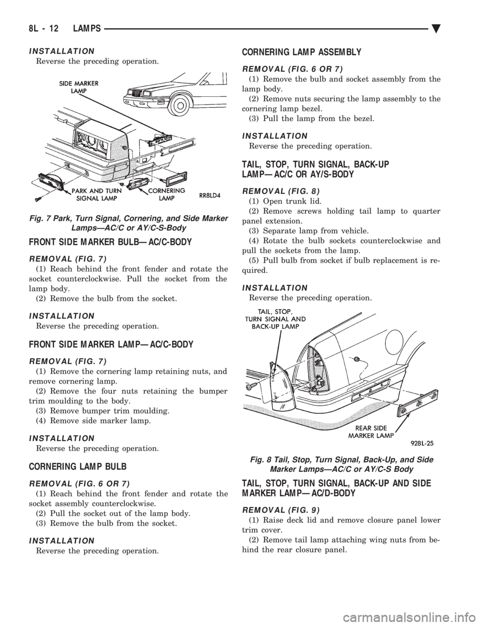
REMOVAL (FIG. 7)
(1) Reach behind the front fender and rotate the
socket counterclockwise. Pull the socket from the
lamp body. (2) Remove the bulb from the socket.
INSTALLATION
Reverse the preceding operation.
FRONT SIDE MARKER LAMPÐAC/C-BODY
REMOVAL (FIG. 7)
(1) Remove the cornering lamp retaining nuts, and
remove cornering lamp. (2) Remove the four nuts retaining the bumper
trim moulding to the body. (3) Remove bumper trim moulding.
(4) Remove side marker lamp.
INSTALLATION
Reverse the preceding operation.
CORNERING LAMP BULB
REMOVAL (FIG. 6 OR 7)
(1) Reach behind the front fender and rotate the
socket assembly counterclockwise. (2) Pull the socket out of the lamp body.
(3) Remove the bulb from the socket.
INSTALLATION
Reverse the preceding operation.
CORNERING LAMP ASSEMBLY
REMOVAL (FIG. 6 OR 7)
(1) Remove the bulb and socket assembly from the
lamp body. (2) Remove nuts securing the lamp assembly to the
cornering lamp bezel. (3) Pull the lamp from the bezel.
INSTALLATION
Reverse the preceding operation.
TAIL, STOP, TURN SIGNAL, BACK-UP
LAMPÐAC/C OR AY/S-BODY
REMOVAL (FIG. 8)
(1) Open trunk lid.
(2) Remove screws holding tail lamp to quarter
panel extension. (3) Separate lamp from vehicle.
(4) Rotate the bulb sockets counterclockwise and
pull the sockets from the lamp. (5) Pull bulb from socket if bulb replacement is re-
quired.
INSTALLATION
Reverse the preceding operation.
TAIL, STOP, TURN SIGNAL, BACK-UP AND SIDE
MARKER LAMPÐAC/D-BODY
REMOVAL (FIG. 9)
(1) Raise deck lid and remove closure panel lower
trim cover. (2) Remove tail lamp attaching wing nuts from be-
hind the rear closure panel.
Fig. 7 Park, Turn Signal, Cornering, and Side Marker LampsÐAC/C or AY/C-S-Body
Fig. 8 Tail, Stop, Turn Signal, Back-Up, and SideMarker LampsÐAC/C or AY/C-S Body
8L - 12 LAMPS Ä
Page 655 of 2438
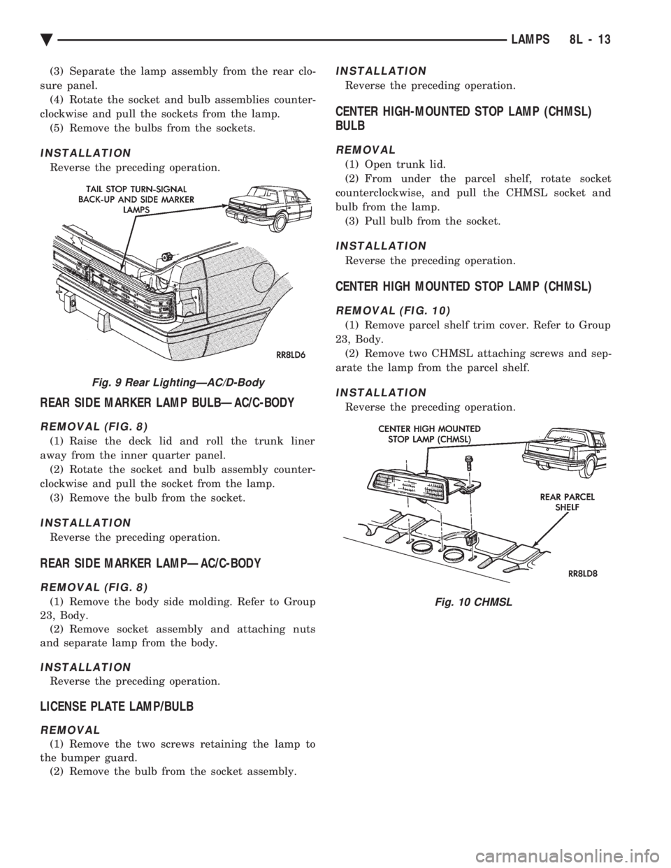
(3) Separate the lamp assembly from the rear clo-
sure panel. (4) Rotate the socket and bulb assemblies counter-
clockwise and pull the sockets from the lamp. (5) Remove the bulbs from the sockets.
INSTALLATION
Reverse the preceding operation.
REAR SIDE MARKER LAMP BULBÐAC/C-BODY
REMOVAL (FIG. 8)
(1) Raise the deck lid and roll the trunk liner
away from the inner quarter panel. (2) Rotate the socket and bulb assembly counter-
clockwise and pull the socket from the lamp. (3) Remove the bulb from the socket.
INSTALLATION
Reverse the preceding operation.
REAR SIDE MARKER LAMPÐAC/C-BODY
REMOVAL (FIG. 8)
(1) Remove the body side molding. Refer to Group
23, Body. (2) Remove socket assembly and attaching nuts
and separate lamp from the body.
INSTALLATION
Reverse the preceding operation.
LICENSE PLATE LAMP/BULB
REMOVAL
(1) Remove the two screws retaining the lamp to
the bumper guard. (2) Remove the bulb from the socket assembly.
INSTALLATION
Reverse the preceding operation.
CENTER HIGH-MOUNTED STOP LAMP (CHMSL)
BULB
REMOVAL
(1) Open trunk lid.
(2) From under the parcel shelf, rotate socket
counterclockwise, and pull the CHMSL socket and
bulb from the lamp. (3) Pull bulb from the socket.
INSTALLATION
Reverse the preceding operation.
CENTER HIGH MOUNTED STOP LAMP (CHMSL)
REMOVAL (FIG. 10)
(1) Remove parcel shelf trim cover. Refer to Group
23, Body. (2) Remove two CHMSL attaching screws and sep-
arate the lamp from the parcel shelf.
INSTALLATION
Reverse the preceding operation.
Fig. 9 Rear LightingÐAC/D-Body
Fig. 10 CHMSL
Ä LAMPS 8L - 13
Page 656 of 2438
EXTERIOR LAMPSÐAG BODY INDEX
page page
Back-Up Lamps .......................... 15
Center High Mounted Stop Lamp Bulb ........ 15
Fog Lamp or Bulb ........................ 14
Headlamp Diagnosis ...................... 14
Headlamp Housing and Bulb ................ 14 License Plate Lamp or Bulb
................ 15
Park and Turn Signal Lamp or Bulb .......... 14
Tail, Stop, Turn Signal, Side Marker, Back-Up Lamp ................................ 15
HEADLAMP DIAGNOSIS
For headlamp diagnosis, refer to the Headlamp Di-
agnosis at the beginning of this Group. Refer to Wir-
ing Diagrams manual for circuit and component
locations.
HEADLAMP HOUSING AND BULB
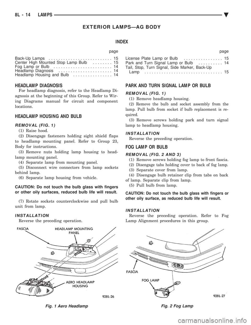
REMOVAL (FIG. 1)
(1) Raise hood.
(2) Disengage fasteners holding sight shield flaps
to headlamp mounting panel. Refer to Group 23,
Body for instructions. (3) Remove nuts holding lamp housing to head-
lamp mounting panel. (4) Separate lamp from mounting panel.
(5) Disconnect wire connectors from lamp sockets
behind lamp. (6) Separate lamp housing from vehicle.
CAUTION: Do not touch the bulb glass with fingers
or other oily surfaces, reduced bulb life will result. (7) Rotate sockets counterclockwise and pull bulb
unit from lamp.
INSTALLATION
Reverse the preceding operation.
PARK AND TURN SIGNAL LAMP OR BULB
REMOVAL (FIG. 1)
(1) Remove headlamp housing.
(2) Remove the bulb and socket assembly from the
lamp. Pull bulb from socket if bulb replacement is re-
quired.
(3) Remove screws holding park and turn signal
lamp to headlamp housing.
INSTALLATION
Reverse the preceding operation.
FOG LAMP OR BULB
REMOVAL (FIG. 2 AND 3)
(1) Remove screws holding fog lamp to front fascia.
(2) Disengage tabs holding cover to back of fog lamp.
(3) Separate cover from lamp.
(4) Disengage bulb retainer clip from tabs on back
of lamp. Separate clip from lamp. (5) Pull bulb from lamp.
CAUTION: Do not touch the bulb glass with fingers or
other oily surface, as reduced bulb life will result.
INSTALLATION
Reverse the preceding operation. Refer to Fog
Lamp Alignment procedures in this group.
Fig. 1 Aero HeadlampFig. 2 Fog Lamp
8L - 14 LAMPS Ä