1993 CHEVROLET PLYMOUTH ACCLAIM clock
[x] Cancel search: clockPage 1286 of 2438
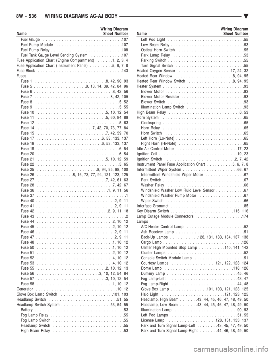
Wiring Diagram
Name Sheet Number
Fuel Gauge ............................. .107
Fuel Pump Module ........................ .107
Fuel Pump Relay .......................... .108
Fuel Tank Gauge Level Sending System ............107
Fuse Application Chart (Engine Compartment) ......1,2,3,4
Fuse Application Chart (Instrument Panel) .........5,6,7,8
Fuse Block ............................... .143
Fuses Fuse 1 ...........................8,42,90,93
Fuse 5 ....................8,13,14,39,42,84,96
Fuse 6 ..............................8,42,56
Fuse 7 .............................8,42,105
Fuse 8 ................................5,52
Fuse 9 ................................5,55
Fuse 10 ..........................5,10,12,54
Fuse 11 ..........................5,60,84,88
Fuse 12 ...............................5,63
Fuse 14 .....................7,42,70,73,77,84
Fuse 15 ..........................7,42,59,70
Fuse 17 .........................6,53, 133, 137
Fuse 18 .........................6,53, 133, 137
Fuse 19 ...............................6,54
Fuse 20 ...............................6,54
Fuse 21 ..........................5,10,12,59
Fuse 22 ...............................5,65
Fuse 25 .......................8,94,95,98,100
Fuse 26 ..............8,16,73,77,94, 121, 123, 125
Fuse 27 ..........................7,42,61,63
Fuse 28 .............................7,42,67
Fuse 36 ...........................1,9,11,56
Fuse 37 ..................................1
Fuse 40 ..............................2,9,11
Fuse 41 ..............................2,9,11
Fuse 42 ...........................2,9,11,18
Fuse 43 ..................................2
Fuse 44 .............................2,10,12
Fuse 45 .............................2,10,12
Fuse 46 ..............................2,9,11
Fuse 47 ..............................2,9,11
Fuse 48 .............................1,10,12
Fuse 50 .............................1,10,12
Fuse 51 .............................2,10,12
Fuse 52 .............................4,10,12
Fuse 53 .............................4,10,12
Fuse 55 ..........................2,10,12,13
Fuse 56 ........................3,10,12,54,84
Fuse 57 ..........................3,10,12,54
Fuse 58 .............................1,10,12
Generator .............................. .10, 12
Glove Box Lamp Switch ................... .101, 103
Headlamp Switch ......................... .51, 55
Headlamp Switch System .................. .53, 54, 55
Battery ..................................53
Fog Lamp Relay ............................55
Fog Lamp Switch ...........................55
Headlamp Switch ...........................55
High Beam Relay ...........................53Wiring Diagram
Name Sheet Number
Left Pod Light .............................55
Low Beam Relay ............................53
Optical Horn Switch .........................55
Park Lamp Relay ...........................53
Parking Switch .............................55
Turn Signal Switch ..........................55
Heated Oxygen Sensor ................... .17, 24, 32
Heated Rear Window ......................8,94,95
Heated Rear Window Switch .................8,94,95
Heater System ...............................93
Blower Motor ..............................93
Blower Motor Resistor ........................93
Blower Switch .............................93
Illumination Lamp Switch ......................93
High Beam Relay ...........................6,53
Horn System ...............................65
Clockspring ...............................65
Horn Relay ...............................65
Horn Switch ..............................65
Left Horn (Lo-Note) ..........................65
Right Horn (Hi-Note) .........................65
Idle Air Control Motor ...................... .17, 23
Ignition Coil ............................. .19, 23
Ignition Switch ...........................2,7,42
Instrument Panel Fuse Application Chart ..........5,6,7,8
Intermittent Wiper System .................... .66, 67
Intermittent Windshield Wiper Motor ...............67
Park Switch ...............................67
Washer Relay .............................66
Windshield Washer Low Fluid Level Sensor ...........67
Windshield Washer Pump Motor .................67
Wiper Switch ..............................66
Interface Grommet ............................85
Key Disarm Switch ....................... .115, 116
Lamp Outage Module Connectors ..................174
Lamps A/C Heater Control Lamp ......................52
Ash Receiver Lamp ..........................51
Back-Up Lamps ...........128, 131, 133, 134, 137, 138
Cargo Lamp ............................. .126
Center High Mounted Stop Lamp ..........140, 141, 142
Cluster Lamps .............................52
Console Switch Module Lamp ...................51
Courtesy Lamps ................ .121, 122, 123, 124
Dome Lamp ......................... .118, 126
Dummy Lamp .......................... .45, 46
Fog Lamp-Left ......................... .43, 47
Fog Lamp-Right ........................ .44, 48
Glove Box Lamp ............. .101, 103, 121, 123, 125
Halo Light ....................... .121, 123, 125
Headlamp, High Beam .......43, 44, 45, 46, 47, 48, 49, 50
Headlamp, Low Beam .......43, 44, 45, 46, 47, 48, 49, 50
Illumination Lamp ....................... .90, 93
Left Pod Lamps ......................... .51, 55
License Lamp .................. .128, 131, 133, 137
Park and Turn Signal Lamp-Left ........43, 45, 47, 49, 50
Park and Turn Signal Lamp-Right .......44, 46, 48, 49, 50
8W - 536 WIRING DIAGRAMS AG-AJ BODY Ä
Page 1290 of 2438
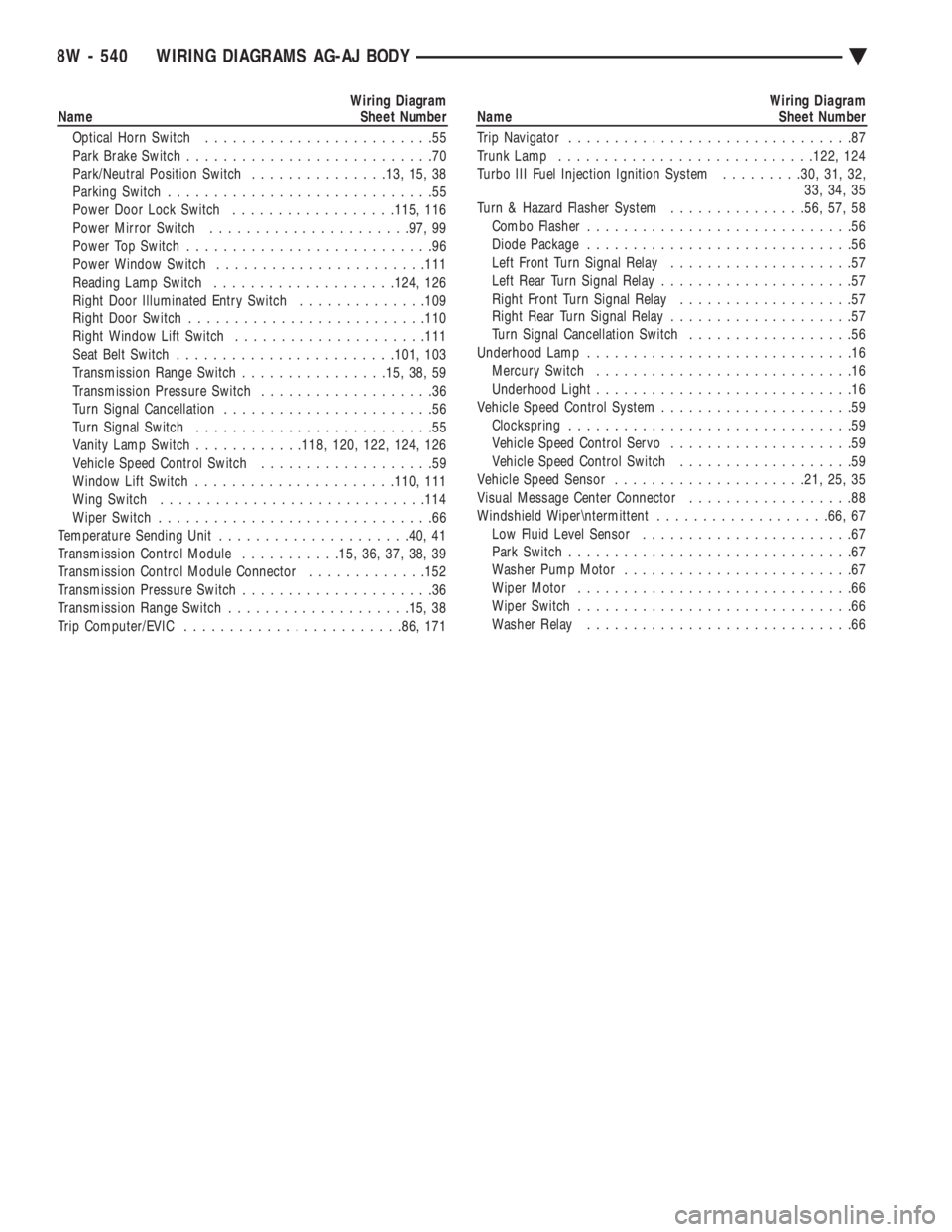
Wiring Diagram
Name Sheet Number
Optical Horn Switch .........................55
Park Brake Switch ...........................70
Park/Neutral Position Switch ...............13, 15, 38
Parking Switch .............................55
Power Door Lock Switch ..................115, 116
Power Mirror Switch ..................... .97, 99
Power Top Switch ...........................96
Power Window Switch ...................... .111
Reading Lamp Switch ................... .124, 126
Right Door Illuminated Entry Switch ..............109
Right Door Switch ......................... .110
Right Window Lift Switch .................... .111
Seat Belt Switch ....................... .101, 103
Transmission Range Switch ................15, 38, 59
Transmission Pressure Switch ...................36
Turn Signal Cancellation .......................56
Turn Signal Switch ..........................55
Vanity Lamp Switch ............118, 120, 122, 124, 126
Vehicle Speed Control Switch ...................59
Window Lift Switch ..................... .110, 111
Wing Switch ............................ .114
Wiper Switch ..............................66
Temperature Sending Unit .................... .40, 41
Transmission Control Module ...........15, 36, 37, 38, 39
Transmission Control Module Connector .............152
Transmission Pressure Switch .....................36
Transmission Range Switch ................... .15, 38
Trip Computer/EVIC ....................... .86, 171Wiring Diagram
Name Sheet Number
Trip Navigator ...............................87
Trunk Lamp ........................... .122, 124
Turbo III Fuel Injection Ignition System .........30, 31, 32,
33, 34, 35
Turn & Hazard Flasher System ...............56, 57, 58
Combo Flasher .............................56
Diode Package .............................56
Left Front Turn Signal Relay ....................57
Left Rear Turn Signal Relay .....................57
Right Front Turn Signal Relay ...................57
Right Rear Turn Signal Relay ....................57
Turn Signal Cancellation Switch ..................56
Underhood Lamp .............................16
Mercury Switch ............................16
Underhood Light ............................16
Vehicle Speed Control System .....................59
Clockspring ...............................59
Vehicle Speed Control Servo ....................59
Vehicle Speed Control Switch ...................59
Vehicle Speed Sensor .................... .21, 25, 35
Visual Message Center Connector ..................88
Windshield Wiper
termittent ...................66, 67
Low Fluid Level Sensor .......................67
Park Switch ...............................67
Washer Pump Motor .........................67
Wiper Motor ..............................66
Wiper Switch ..............................66
Washer Relay .............................66
8W - 540 WIRING DIAGRAMS AG-AJ BODY Ä
Page 1467 of 2438
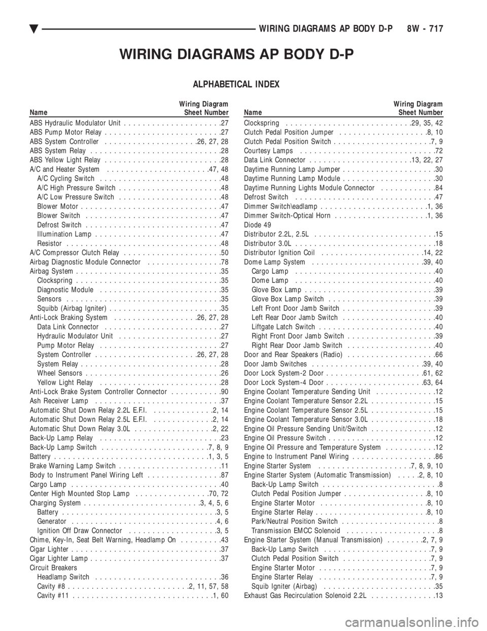
WIRING DIAGRAMS AP BODY D-P
ALPHABETICAL INDEX
Wiring Diagram
Name Sheet Number
ABS Hydraulic Modulator Unit .....................27
ABS Pump Motor Relay .........................27
ABS System Controller ................... .26, 27, 28
ABS System Relay ............................28
ABS Yellow Light Relay .........................28
A/C and Heater System ..................... .47, 48
A/C Cycling Switch ..........................48
A/C High Pressure Switch ......................48
A/C Low Pressure Switch ......................48
Blower Motor ..............................47
Blower Switch .............................47
Defrost Switch .............................47
Illumination Lamp ...........................47
Resistor .................................48
A/C Compressor Clutch Relay .....................50
Airbag Diagnostic Module Connector ................78
Airbag System ...............................35
Clockspring ...............................35
Diagnostic Module ..........................35
Sensors .................................35
Squibb (Airbag Igniter) ........................35
Anti-Lock Braking System ..................26, 27, 28
Data Link Connector .........................27
Hydraulic Modulator Unit ......................27
Pump Motor Relay ..........................27
System Controller ..................... .26, 27, 28
System Relay ..............................28
Wheel Sensors .............................26
Yellow Light Relay ..........................28
Anti-Lock Brake System Controller Connector ...........90
Ash Receiver Lamp ...........................37
Automatic Shut Down Relay 2.2L E.F.I. .............2,14
Automatic Shut Down Relay 2.5L E.F.I. .............2,14
Automatic Shut Down Relay 3.0L .................2,22
Back-Up Lamp Relay ..........................23
Back-Up Lamp Switch .......................7,8,9
Battery .................................1,3,5
Brake Warning Lamp Switch ......................11
Body to Instrument Panel Wiring Left ................87
Cargo Lamp ................................40
Center High Mounted Stop Lamp ................70, 72
Charging System .........................3,4,5,6
Battery .................................3,5
Generator ...............................4,6
Ignition Off Draw Connector ...................3,5
Chime, Key-In, Seat Belt Warning, Headlamp On .........43
Cigar Lighter ................................37
Cigar Lighter Lamp ............................37
Circuit Breakers Headlamp Switch ...........................36
Cavity #8 ..........................2,11,57,58
Cavity #11 ..............................1,60Wiring Diagram
Name Sheet Number
Clockspring .......................... .29, 35, 42
Clutch Pedal Position Jumper ...................8,10
Clutch Pedal Position Switch .....................7,9
Courtesy Lamps .............................72
Data Link Connector ..................... .13, 22, 27
Daytime Running Lamp Jumper ....................30
Daytime Running Lamp Module ....................30
Daytime Running Lights Module Connector ............84
Defrost Switch ..............................47
Dimmer Switch\eadlamp .......................1,36
Dimmer Switch-Optical Horn ....................1,36
Diode 49
Distributor 2.2L, 2.5L ..........................15
Distributor 3.0L ..............................18
Distributor Ignition Coil ..................... .14, 22
Dome Lamp System ....................... .39, 40
Cargo Lamp ..............................40
Dome Lamp ..............................40
Glove Box Lamp ............................39
Glove Box Lamp Switch .......................39
Left Front Door Jamb Switch ....................39
Left Rear Door Jamb Switch ....................40
Liftgate Latch Switch .........................40
Right Front Door Jamb Switch ...................39
Right Rear Door Jamb Switch ...................40
Door and Rear Speakers (Radio) ...................66
Door Jamb Switches ....................... .39, 40
Door Lock System-2 Door .................... .61, 62
Door Lock System-4 Door .................... .63, 64
Engine Coolant Temperature Sending Unit .............12
Engine Coolant Temperature Sensor 2.2L ..............15
Engine Coolant Temperature Sensor 2.5L ..............15
Engine Coolant Temperature Sensor 3.0L ..............18
Engine Oil Pressure Sending Unit/Switch ..............12
Engine Oil Pressure Switch .......................12
Engine Oil Pressure and Temperature System ...........12
Engine to Instrument Panel Wiring ..................86
Engine Starter System ....................7,8,9,10
Engine Starter System (Automatic Transmission) .....2,8,10
Back-Up Lamp Switch .........................8
Clutch Pedal Position Jumper ..................8,10
Engine Starter Motor .......................8,10
Engine Starter Relay ........................8,10
Park/Neutral Position Switch .....................8
Transmission EMCC Solenoid ....................8
Engine Starter System (Manual Transmission) ........2,7,9
Back-Up Lamp Switch .......................7,9
Clutch Pedal Position Switch ...................7,9
Engine Starter Motor ........................7,9
Engine Starter Relay ........................7,9
Squib Igniter (Airbag) ........................35
Exhaust Gas Recirculation Solenoid 2.2L ..............13
Ä WIRING DIAGRAMS AP BODY D-P 8W - 717
Page 1468 of 2438
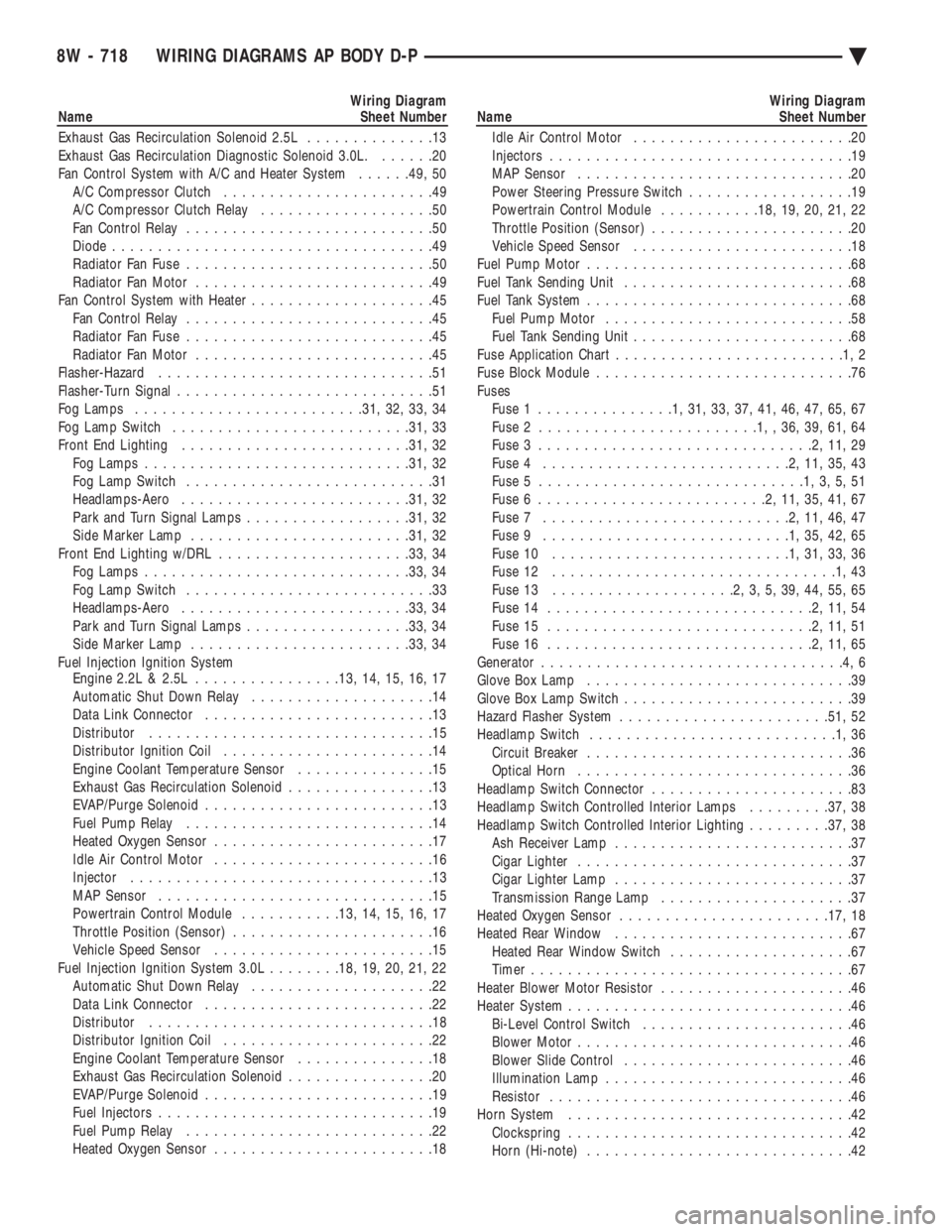
Wiring Diagram
Name Sheet Number
Exhaust Gas Recirculation Solenoid 2.5L ..............13
Exhaust Gas Recirculation Diagnostic Solenoid 3.0L. ......20
Fan Control System with A/C and Heater System ......49, 50
A/C Compressor Clutch .......................49
A/C Compressor Clutch Relay ...................50
Fan Control Relay ...........................50
Diode ...................................49
Radiator Fan Fuse ...........................50
Radiator Fan Motor ..........................49
Fan Control System with Heater ....................45
Fan Control Relay ...........................45
Radiator Fan Fuse ...........................45
Radiator Fan Motor ..........................45
Flasher-Hazard ..............................51
Flasher-Turn Signal ............................51
Fog Lamps ........................ .31, 32, 33, 34
Fog Lamp Switch ......................... .31, 33
Front End Lighting ........................ .31, 32
Fog Lamps ............................ .31, 32
Fog Lamp Switch ...........................31
Headlamps-Aero ........................ .31, 32
Park and Turn Signal Lamps ..................31, 32
Side Marker Lamp ....................... .31, 32
Front End Lighting w/DRL .................... .33, 34
Fog Lamps ............................ .33, 34
Fog Lamp Switch ...........................33
Headlamps-Aero ........................ .33, 34
Park and Turn Signal Lamps ..................33, 34
Side Marker Lamp ....................... .33, 34
Fuel Injection Ignition System Engine 2.2L & 2.5L ............... .13, 14, 15, 16, 17
Automatic Shut Down Relay ....................14
Data Link Connector .........................13
Distributor ...............................15
Distributor Ignition Coil .......................14
Engine Coolant Temperature Sensor ...............15
Exhaust Gas Recirculation Solenoid ................13
EVAP/Purge Solenoid .........................13
Fuel Pump Relay ...........................14
Heated Oxygen Sensor ........................17
Idle Air Control Motor ........................16
Injector .................................13
MAP Sensor ..............................15
Powertrain Control Module ...........13, 14, 15, 16, 17
Throttle Position (Sensor) ......................16
Vehicle Speed Sensor ........................15
Fuel Injection Ignition System 3.0L ........18, 19, 20, 21, 22
Automatic Shut Down Relay ....................22
Data Link Connector .........................22
Distributor ...............................18
Distributor Ignition Coil .......................22
Engine Coolant Temperature Sensor ...............18
Exhaust Gas Recirculation Solenoid ................20
EVAP/Purge Solenoid .........................19
Fuel Injectors ..............................19
Fuel Pump Relay ...........................22
Heated Oxygen Sensor ........................18Wiring Diagram
Name Sheet Number
Idle Air Control Motor ........................20
Injectors .................................19
MAP Sensor ..............................20
Power Steering Pressure Switch ..................19
Powertrain Control Module ...........18, 19, 20, 21, 22
Throttle Position (Sensor) ......................20
Vehicle Speed Sensor ........................18
Fuel Pump Motor .............................68
Fuel Tank Sending Unit .........................68
Fuel Tank System .............................68
Fuel Pump Motor ...........................58
Fuel Tank Sending Unit ........................68
Fuse Application Char t.........................1,2
Fuse Block Module ............................76
Fuses Fuse 1 ...............1,31,33,37,41,46,47,65,67
Fuse 2 ........................1,,36,39,61,64
Fuse 3 ..............................2,11,29
Fuse 4 ...........................2,11,35,43
Fuse 5 .............................1,3,5,51
Fuse 6 .........................2,11,35,41,67
Fuse 7 ...........................2,11,46,47
Fuse 9 ...........................1,35,42,65
Fuse 10 ..........................1,31,33,36
Fuse 12 ...............................1,43
Fuse 13 ....................2,3,5,39,44,55,65
Fuse 14 .............................2,11,54
Fuse 15 .............................2,11,51
Fuse 16 .............................2,11,65
Generator .................................4,6
Glove Box Lamp .............................39
Glove Box Lamp Switch .........................39
Hazard Flasher System ...................... .51, 52
Headlamp Switch ...........................1,36
Circuit Breaker .............................36
Optical Horn ..............................36
Headlamp Switch Connector ......................83
Headlamp Switch Controlled Interior Lamps .........37, 38
Headlamp Switch Controlled Interior Lighting .........37, 38
Ash Receiver Lamp ..........................37
Cigar Lighter ..............................37
Cigar Lighter Lamp ..........................37
Transmission Range Lamp .....................37
Heated Oxygen Sensor ...................... .17, 18
Heated Rear Window ..........................67
Heated Rear Window Switch ....................67
Timer ...................................67
Heater Blower Motor Resistor .....................46
Heater System ...............................46
Bi-Level Control Switch .......................46
Blower Motor ..............................46
Blower Slide Control .........................46
Illumination Lamp ...........................46
Resistor .................................46
Horn System ...............................42
Clockspring ...............................42
Horn (Hi-note) .............................42
8W - 718 WIRING DIAGRAMS AP BODY D-P Ä
Page 1471 of 2438
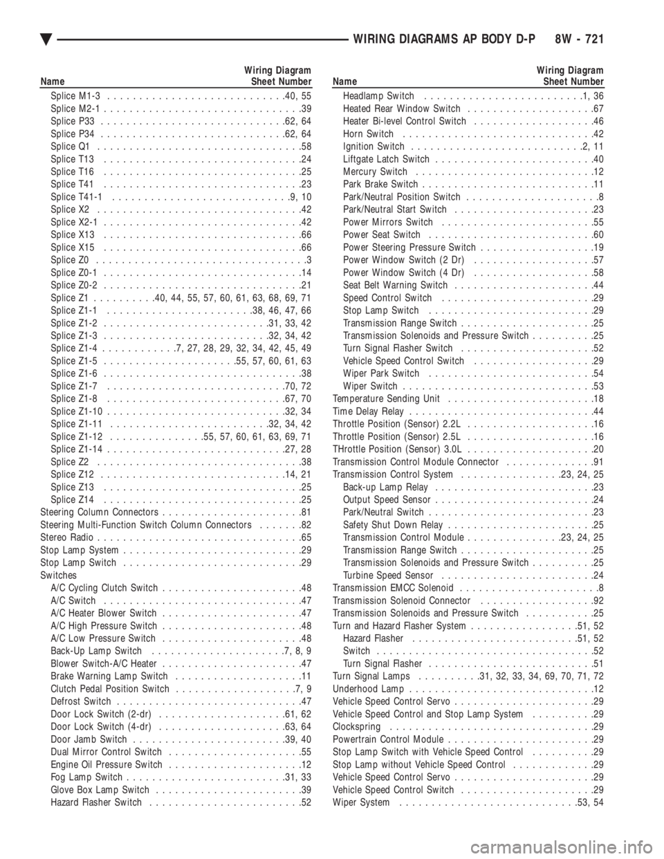
Wiring Diagram
Name Sheet Number
Splice M1-3 ........................... .40, 55
Splice M2-1 ...............................39
Splice P33 ............................ .62, 64
Splice P34 ............................ .62, 64
Splice Q1 ................................58
Splice T13 ...............................24
Splice T16 ...............................25
Splice T41 ...............................23
Splice T41-1 ............................9,10
Splice X2 ................................42
Splice X2-1 ...............................42
Splice X13 ...............................66
Splice X15 ...............................66
Splice Z0 .................................3
Splice Z0-1 ...............................14
Splice Z0-2 ...............................21
Splice Z1 ......... .40, 44, 55, 57, 60, 61, 63, 68, 69, 71
Splice Z1-1 ...................... .38, 46, 47, 66
Splice Z1-2 ......................... .31, 33, 42
Splice Z1-3 ......................... .32, 34, 42
Splice Z1-4 ............7,27,28,29,32,34,42,45,49
Splice Z1-5 .................... .55, 57, 60, 61, 63
Splice Z1-6 ...............................38
Splice Z1-7 ........................... .70, 72
Splice Z1-8 ........................... .67, 70
Splice Z1-10 ........................... .32, 34
Splice Z1-11 ........................ .32, 34, 42
Splice Z1-12 .............. .55, 57, 60, 61, 63, 69, 71
Splice Z1-14 ........................... .27, 28
Splice Z2 ................................38
Splice Z12 ............................ .14, 21
Splice Z13 ...............................25
Splice Z14 ...............................25
Steering Column Connectors ......................81
Steering Multi-Function Switch Column Connectors .......82
Stereo Radio ................................65
Stop Lamp System ............................29
Stop Lamp Switch ............................29
Switches A/C Cycling Clutch Switch ......................48
A/C Switch ...............................47
A/C Heater Blower Switch ......................47
A/C High Pressure Switch ......................48
A/C Low Pressure Switch ......................48
Back-Up Lamp Switch .....................7,8,9
Blower Switch-A/C Heater ......................47
Brake Warning Lamp Switch ....................11
Clutch Pedal Position Switch ...................7,9
Defrost Switch .............................47
Door Lock Switch (2-dr) ................... .61, 62
Door Lock Switch (4-dr) ................... .63, 64
Door Jamb Switch ....................... .39, 40
Dual Mirror Control Switch .....................55
Engine Oil Pressure Switch .....................12
Fog Lamp Switch ........................ .31, 33
Glove Box Lamp Switch .......................39
Hazard Flasher Switch ........................52Wiring Diagram
Name Sheet Number
Headlamp Switch .........................1,36
Heated Rear Window Switch ....................67
Heater Bi-level Control Switch ...................46
Horn Switch ..............................42
Ignition Switch ...........................2,11
Liftgate Latch Switch .........................40
Mercury Switch ............................12
Park Brake Switch ...........................11
Park/Neutral Position Switch .....................8
Park/Neutral Start Switch ......................23
Power Mirrors Switch ........................55
Power Seat Switch ..........................60
Power Steering Pressure Switch ..................19
Power Window Switch (2 Dr) ...................57
Power Window Switch (4 Dr) ...................58
Seat Belt Warning Switch ......................44
Speed Control Switch ........................29
Stop Lamp Switch ..........................29
Transmission Range Switch .....................25
Transmission Solenoids and Pressure Switch ..........25
Turn Signal Flasher Switch .....................52
Vehicle Speed Control Switch ...................29
Wiper Park Switch ..........................54
Wiper Switch ..............................53
Temperature Sending Unit .......................18
Time Delay Relay .............................44
Throttle Position (Sensor) 2.2L ....................16
Throttle Position (Sensor) 2.5L ....................16
THrottle Position (Sensor) 3.0L ....................20
Transmission Control Module Connector ..............91
Transmission Control System ................23, 24, 25
Back-up Lamp Relay .........................23
Output Speed Sensor .........................24
Park/Neutral Switch ..........................23
Safety Shut Down Relay .......................25
Transmission Control Module ...............23, 24, 25
Transmission Range Switch .....................25
Transmission Solenoids and Pressure Switch ..........25
Turbine Speed Sensor ........................24
Transmission EMCC Solenoid ......................8
Transmission Solenoid Connector ..................92
Transmission Solenoids and Pressure Switch ...........25
Turn and Hazard Flasher System .................51, 52
Hazard Flasher ......................... .51, 52
Switch ..................................52
Turn Signal Flasher ..........................51
Turn Signal Lamps ..........31, 32, 33, 34, 69, 70, 71, 72
Underhood Lamp .............................12
Vehicle Speed Control Servo ......................29
Vehicle Speed Control and Stop Lamp System ..........29
Clockspring ................................29
Powertrain Control Module .......................29
Stop Lamp Switch with Vehicle Speed Control ..........29
Stop Lamp without Vehicle Speed Control .............29
Vehicle Speed Control Servo ......................29
Vehicle Speed Control Switch .....................29
Wiper System ........................... .53, 54
Ä WIRING DIAGRAMS AP BODY D-P 8W - 721
Page 1587 of 2438
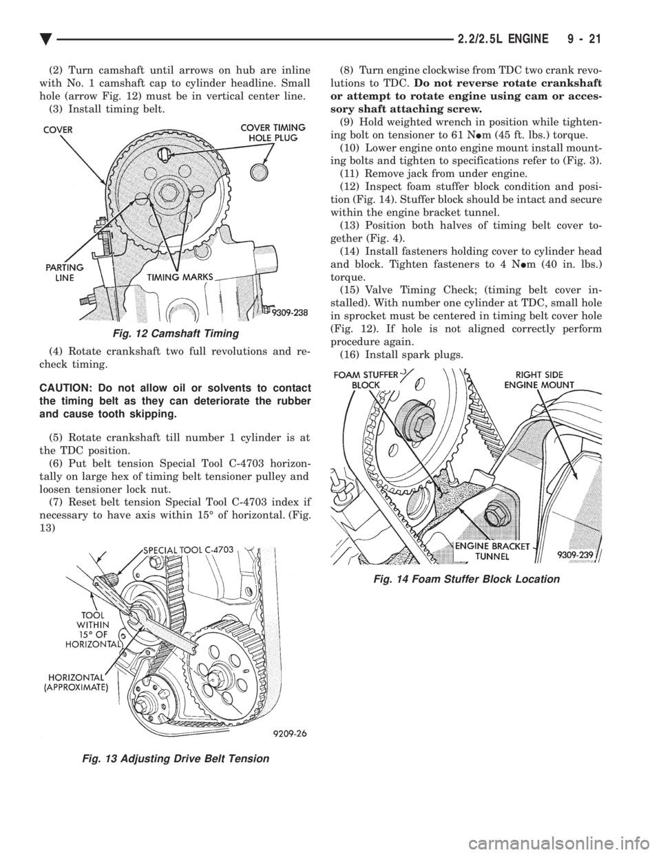
(2) Turn camshaft until arrows on hub are inline
with No. 1 camshaft cap to cylinder headline. Small
hole (arrow Fig. 12) must be in vertical center line. (3) Install timing belt.
(4) Rotate crankshaft two full revolutions and re-
check timing.
CAUTION: Do not allow oil or solvents to contact
the timing belt as they can deteriorate the rubber
and cause tooth skipping.
(5) Rotate crankshaft till number 1 cylinder is at
the TDC position. (6) Put belt tension Special Tool C-4703 horizon-
tally on large hex of timing belt tensioner pulley and
loosen tensioner lock nut. (7) Reset belt tension Special Tool C-4703 index if
necessary to have axis within 15É of horizontal. (Fig.
13) (8) Turn engine clockwise from TDC two crank revo-
lutions to TDC. Do not reverse rotate crankshaft
or attempt to rotate engine using cam or acces-
sory shaft attaching screw. (9) Hold weighted wrench in position while tighten-
ing bolt on tensioner to 61 N Im (45 ft. lbs.) torque.
(10) Lower engine onto engine mount install mount-
ing bolts and tighten to specifications refer to (Fig. 3). (11) Remove jack from under engine.
(12) Inspect foam stuffer block condition and posi-
tion (Fig. 14). Stuffer block should be intact and secure
within the engine bracket tunnel. (13) Position both halves of timing belt cover to-
gether (Fig. 4). (14) Install fasteners holding cover to cylinder head
and block. Tighten fasteners to 4 N Im (40 in. lbs.)
torque. (15) Valve Timing Check; (timing belt cover in-
stalled). With number one cylinder at TDC, small hole
in sprocket must be centered in timing belt cover hole
(Fig. 12). If hole is not aligned correctly perform
procedure again. (16) Install spark plugs.
Fig. 12 Camshaft Timing
Fig. 13 Adjusting Drive Belt Tension
Fig. 14 Foam Stuffer Block Location
Ä 2.2/2.5L ENGINE 9 - 21
Page 1600 of 2438
CAMSHAFT AND CRANKSHAFT TIMING
PROCEDURE
INSTALLATION
(1) Remove air cleaner fresh air duct.
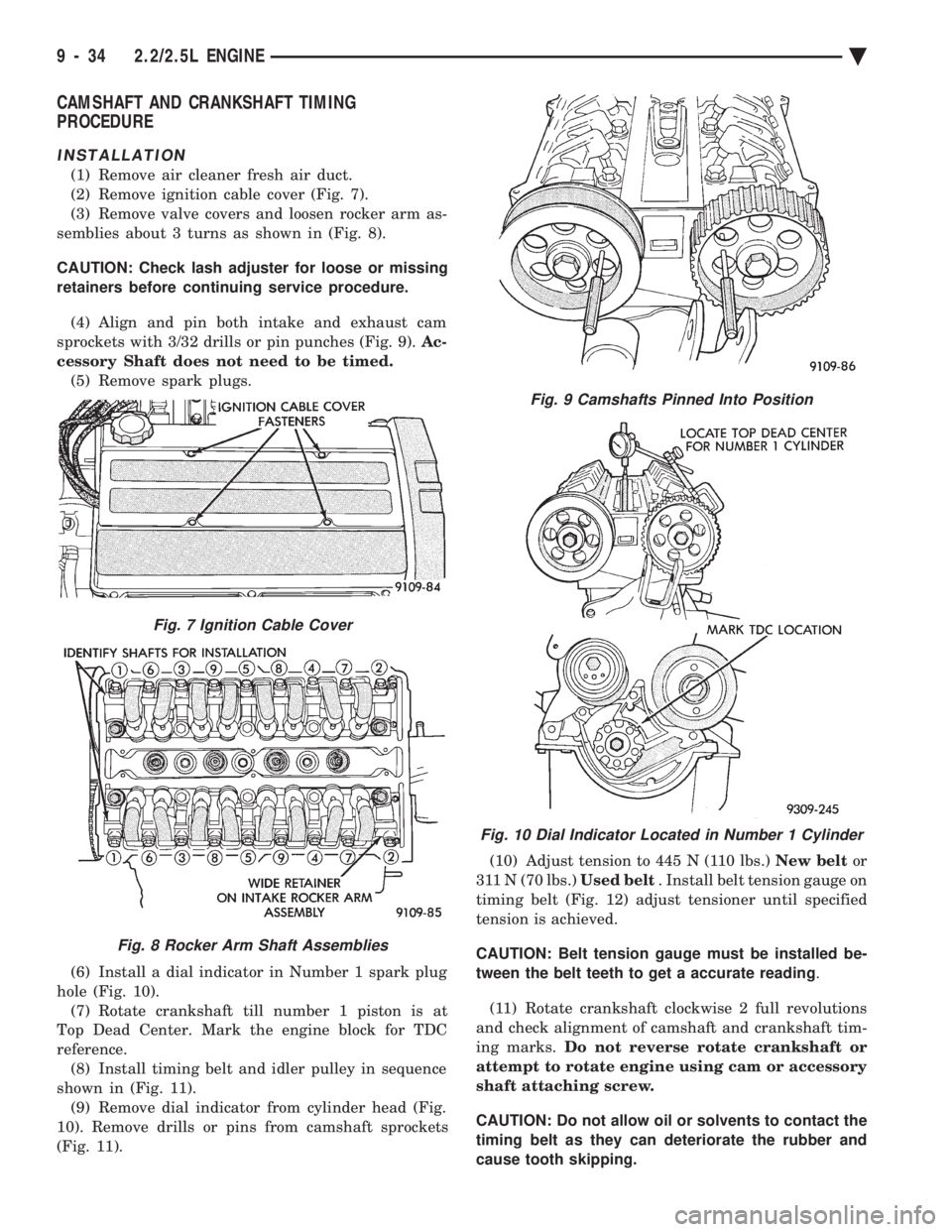
(2) Remove ignition cable cover (Fig. 7).
(3) Remove valve covers and loosen rocker arm as-
semblies about 3 turns as shown in (Fig. 8).
CAUTION: Check lash adjuster for loose or missing
retainers before continuing service procedure.
(4) Align and pin both intake and exhaust cam
sprockets with 3/32 drills or pin punches (Fig. 9). Ac-
cessory Shaft does not need to be timed. (5) Remove spark plugs.
(6) Install a dial indicator in Number 1 spark plug
hole (Fig. 10). (7) Rotate crankshaft till number 1 piston is at
Top Dead Center. Mark the engine block for TDC
reference. (8) Install timing belt and idler pulley in sequence
shown in (Fig. 11). (9) Remove dial indicator from cylinder head (Fig.
10). Remove drills or pins from camshaft sprockets
(Fig. 11). (10) Adjust tension to 445 N (110 lbs.)
New beltor
311 N (70 lbs.) Used belt. Install belt tension gauge on
timing belt (Fig. 12) adjust tensioner until specified
tension is achieved.
CAUTION: Belt tension gauge must be installed be-
tween the belt teeth to get a accurate reading .
(11) Rotate crankshaft clockwise 2 full revolutions
and check alignment of camshaft and crankshaft tim-
ing marks. Do not reverse rotate crankshaft or
attempt to rotate engine using cam or accessory
shaft attaching screw.
CAUTION: Do not allow oil or solvents to contact the
timing belt as they can deteriorate the rubber and
cause tooth skipping.
Fig. 7 Ignition Cable Cover
Fig. 8 Rocker Arm Shaft Assemblies
Fig. 9 Camshafts Pinned Into Position
Fig. 10 Dial Indicator Located in Number 1 Cylinder
9 - 34 2.2/2.5L ENGINE Ä
Page 1609 of 2438
CRANKSHAFT SERVICE
CRANKSHAFT MAIN BEARINGS
Bearing caps are not interchangeable and should
be marked at removal to insure correct assembly.
Upper and lower bearing halves are NOT inter-
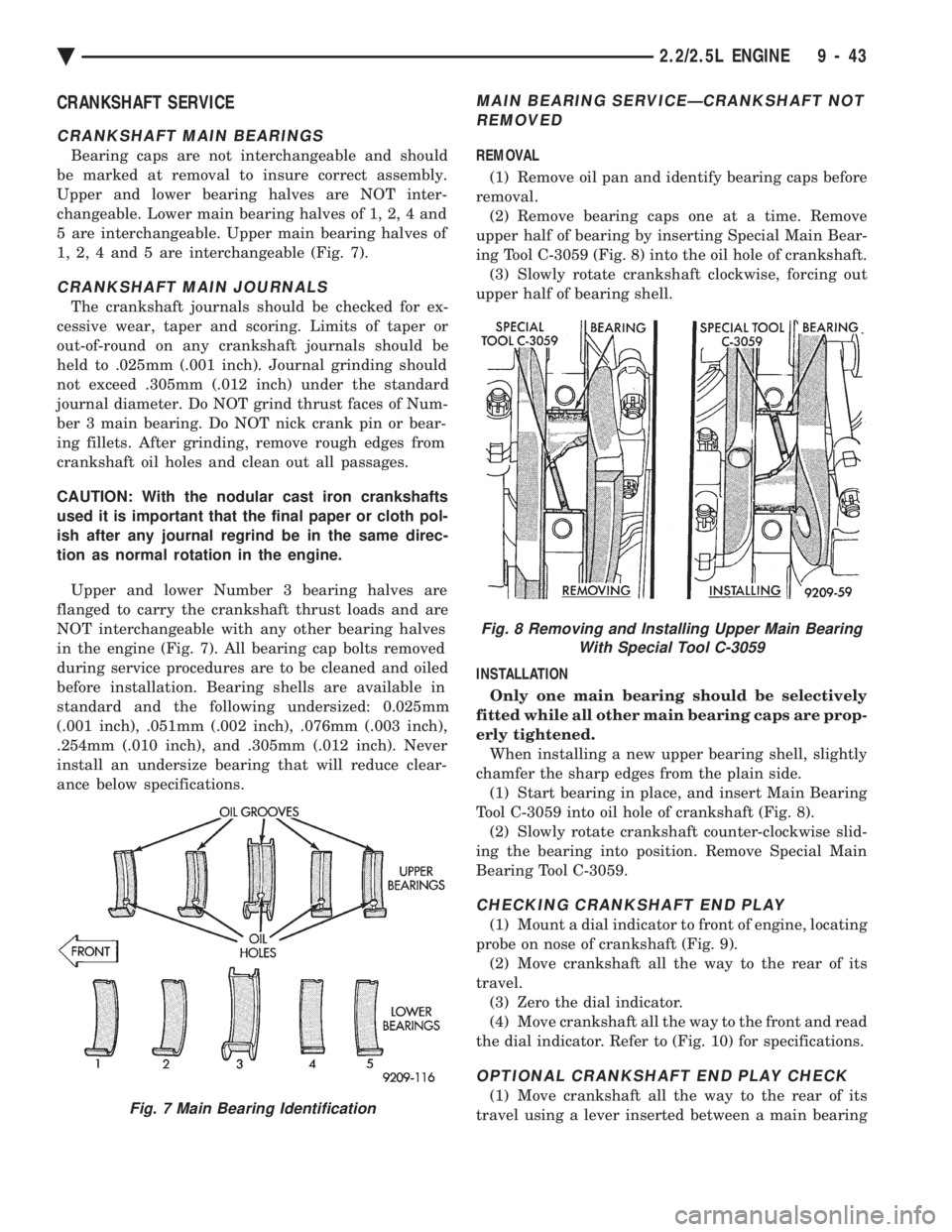
changeable. Lower main bearing halves of 1, 2, 4 and
5 are interchangeable. Upper main bearing halves of
1, 2, 4 and 5 are interchangeable (Fig. 7).
CRANKSHAFT MAIN JOURNALS
The crankshaft journals should be checked for ex-
cessive wear, taper and scoring. Limits of taper or
out-of-round on any crankshaft journals should be
held to .025mm (.001 inch). Journal grinding should
not exceed .305mm (.012 inch) under the standard
journal diameter. Do NOT grind thrust faces of Num-
ber 3 main bearing. Do NOT nick crank pin or bear-
ing fillets. After grinding, remove rough edges from
crankshaft oil holes and clean out all passages.
CAUTION: With the nodular cast iron crankshafts
used it is important that the final paper or cloth pol-
ish after any journal regrind be in the same direc-
tion as normal rotation in the engine.
Upper and lower Number 3 bearing halves are
flanged to carry the crankshaft thrust loads and are
NOT interchangeable with any other bearing halves
in the engine (Fig. 7). All bearing cap bolts removed
during service procedures are to be cleaned and oiled
before installation. Bearing shells are available in
standard and the following undersized: 0.025mm
(.001 inch), .051mm (.002 inch), .076mm (.003 inch),
.254mm (.010 inch), and .305mm (.012 inch). Never
install an undersize bearing that will reduce clear-
ance below specifications.
MAIN BEARING SERVICEÐCRANKSHAFT NOT REMOVED
REMOVAL
(1) Remove oil pan and identify bearing caps before
removal. (2) Remove bearing caps one at a time. Remove
upper half of bearing by inserting Special Main Bear-
ing Tool C-3059 (Fig. 8) into the oil hole of crankshaft. (3) Slowly rotate crankshaft clockwise, forcing out
upper half of bearing shell.
INSTALLATION Only one main bearing should be selectively
fitted while all other main bearing caps are prop-
erly tightened. When installing a new upper bearing shell, slightly
chamfer the sharp edges from the plain side. (1) Start bearing in place, and insert Main Bearing
Tool C-3059 into oil hole of crankshaft (Fig. 8). (2) Slowly rotate crankshaft counter-clockwise slid-
ing the bearing into position. Remove Special Main
Bearing Tool C-3059.
CHECKING CRANKSHAFT END PLAY
(1) Mount a dial indicator to front of engine, locating
probe on nose of crankshaft (Fig. 9). (2) Move crankshaft all the way to the rear of its
travel. (3) Zero the dial indicator.
(4) Move crankshaft all the way to the front and read
the dial indicator. Refer to (Fig. 10) for specifications.
OPTIONAL CRANKSHAFT END PLAY CHECK
(1) Move crankshaft all the way to the rear of its
travel using a lever inserted between a main bearingFig. 7 Main Bearing Identification
Fig. 8 Removing and Installing Upper Main Bearing With Special Tool C-3059
Ä 2.2/2.5L ENGINE 9 - 43