1993 CHEVROLET PLYMOUTH ACCLAIM clock
[x] Cancel search: clockPage 2313 of 2438
REFRIGERANT RECYCLING
(R-12) refrigerant is a chlorofluorocarbon (CFC)
that can contribute to the depletion of the ozone
layer in the upper atmosphere. To help protect the
ozone layer, an R-12 recycling device must be used.
Contact an automotive service equipment supplier
for refrigerant recycling equipment. Refer to the op-
erating instructions provided with the recycling
equipment for proper operation.
MANIFOLD GAUGE SET CONNECTIONS
GENERAL INFORMATION
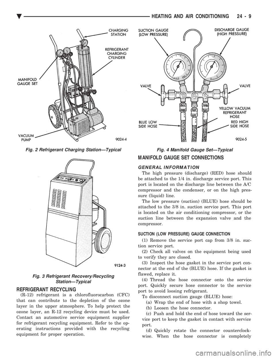
The high pressure (discharge) (RED) hose should
be attached to the 1/4 in. discharge service port. This
port is located on the discharge line between the A/C
compressor and the condenser, or on the high pres-
sure (liquid) line. The low pressure (suction) (BLUE) hose should be
attached to the 3/8 in. suction service port. This port
is located on the air conditioning compressor, or the
suction line between the expansion valve and the
compressor.
SUCTION (LOW PRESSURE) GAUGE CONNECTION
(1) Remove the service port cap from 3/8 in. suc-
tion service port. (2) Check all valves on the equipment being used
to verify they are closed. (3) Inspect the hose gasket in the service port con-
nector at the end of the (BLUE) hose. If the gasket is
flawed, replace it. (4) Thread the hose connector onto the service
port. Quickly secure hose connector to the service
port to avoid loosing refrigerant. To disconnect suction gauge (BLUE) hose:(a) Wrap the end of hose with a shop towel.
(b) Loosen the hose connector.
(c) Push and hold the end of hose toward the ser-
vice port to keep the gasket in contact with service
port. (d) Quickly rotate the connector counterclock-
wise. When the hose connector is completely
Fig. 2 Refrigerant Charging StationÐTypical
Fig. 3 Refrigerant Recovery/Recycling StationÐTypical
Fig. 4 Manifold Gauge SetÐTypical
Ä HEATING AND AIR CONDITIONING 24 - 9
Page 2314 of 2438
backed off, immediately point the end of hose toward
floor, as possibly trapped refrigerant in the hose will
be released.(e) Install service port cap.
DISCHARGE (HIGH PRESSURE) GAUGE CONNECTION (1) Remove the service port cap from the 1/4 in.
service port. (2) Check all valves on the equipment being used to
verify they are closed. (3) Inspect the hose gasket in the service port con-
nector at the end of the (RED) hose. If the gasket is
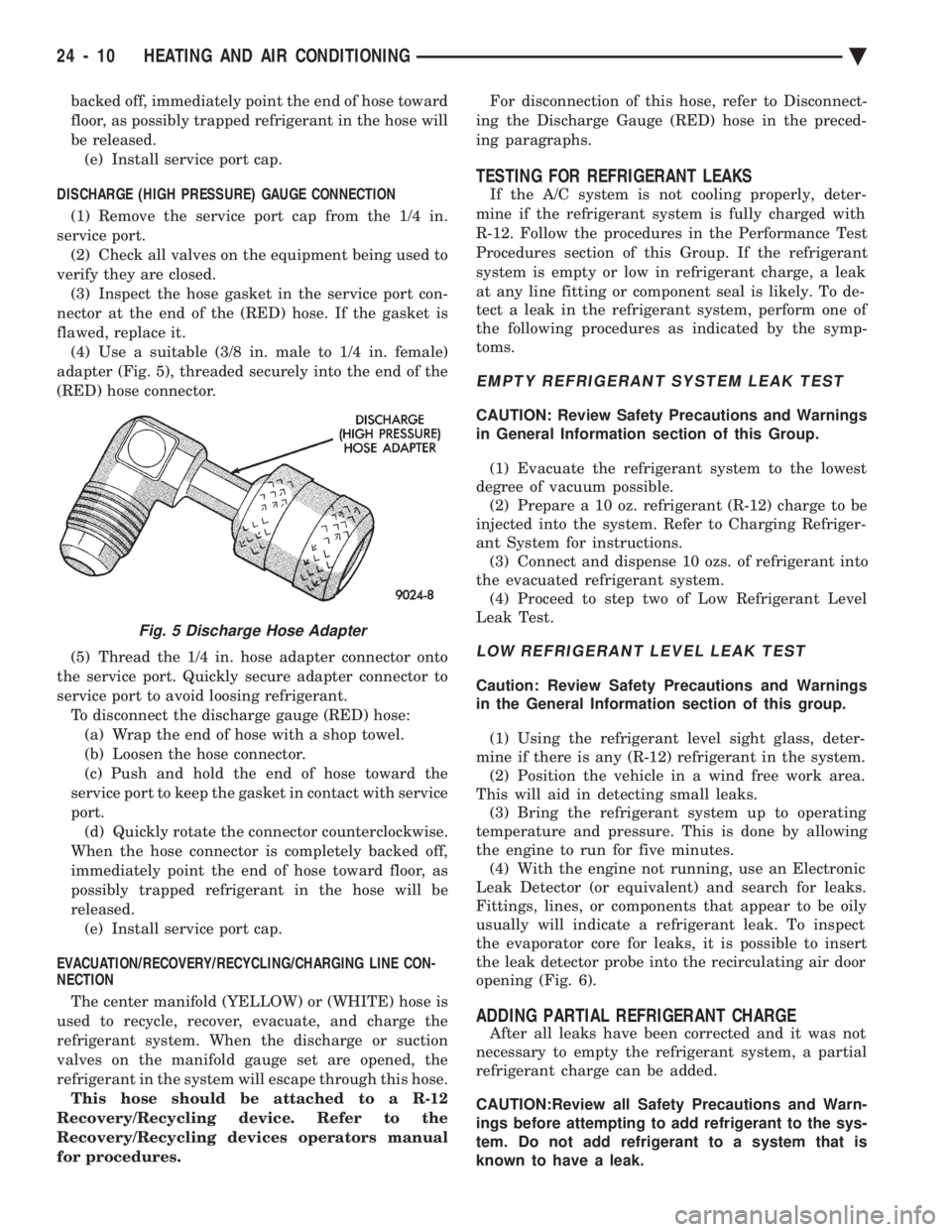
flawed, replace it. (4) Use a suitable (3/8 in. male to 1/4 in. female)
adapter (Fig. 5), threaded securely into the end of the
(RED) hose connector.
(5) Thread the 1/4 in. hose adapter connector onto
the service port. Quickly secure adapter connector to
service port to avoid loosing refrigerant. To disconnect the discharge gauge (RED) hose:(a) Wrap the end of hose with a shop towel.
(b) Loosen the hose connector.
(c) Push and hold the end of hose toward the
service port to keep the gasket in contact with service
port. (d) Quickly rotate the connector counterclockwise.
When the hose connector is completely backed off,
immediately point the end of hose toward floor, as
possibly trapped refrigerant in the hose will be
released. (e) Install service port cap.
EVACUATION/RECOVERY/RECYCLING/CHARGING LINE CON-
NECTION
The center manifold (YELLOW) or (WHITE) hose is
used to recycle, recover, evacuate, and charge the
refrigerant system. When the discharge or suction
valves on the manifold gauge set are opened, the
refrigerant in the system will escape through this hose. This hose should be attached to a R-12
Recovery/Recycling device. Refer to the
Recovery/Recycling devices operators manual
for procedures. For disconnection of this hose, refer to Disconnect-
ing the Discharge Gauge (RED) hose in the preced-
ing paragraphs.
TESTING FOR REFRIGERANT LEAKS
If the A/C system is not cooling properly, deter-
mine if the refrigerant system is fully charged with
R-12. Follow the procedures in the Performance Test
Procedures section of this Group. If the refrigerant
system is empty or low in refrigerant charge, a leak
at any line fitting or component seal is likely. To de-
tect a leak in the refrigerant system, perform one of
the following procedures as indicated by the symp-
toms.
EMPTY REFRIGERANT SYSTEM LEAK TEST
CAUTION: Review Safety Precautions and Warnings
in General Information section of this Group.
(1) Evacuate the refrigerant system to the lowest
degree of vacuum possible. (2) Prepare a 10 oz. refrigerant (R-12) charge to be
injected into the system. Refer to Charging Refriger-
ant System for instructions. (3) Connect and dispense 10 ozs. of refrigerant into
the evacuated refrigerant system. (4) Proceed to step two of Low Refrigerant Level
Leak Test.
LOW REFRIGERANT LEVEL LEAK TEST
Caution: Review Safety Precautions and Warnings
in the General Information section of this group.
(1) Using the refrigerant level sight glass, deter-
mine if there is any (R-12) refrigerant in the system. (2) Position the vehicle in a wind free work area.
This will aid in detecting small leaks. (3) Bring the refrigerant system up to operating
temperature and pressure. This is done by allowing
the engine to run for five minutes. (4) With the engine not running, use an Electronic
Leak Detector (or equivalent) and search for leaks.
Fittings, lines, or components that appear to be oily
usually will indicate a refrigerant leak. To inspect
the evaporator core for leaks, it is possible to insert
the leak detector probe into the recirculating air door
opening (Fig. 6).
ADDING PARTIAL REFRIGERANT CHARGE
After all leaks have been corrected and it was not
necessary to empty the refrigerant system, a partial
refrigerant charge can be added.
CAUTION:Review all Safety Precautions and Warn-
ings before attempting to add refrigerant to the sys-
tem. Do not add refrigerant to a system that is
known to have a leak.
Fig. 5 Discharge Hose Adapter
24 - 10 HEATING AND AIR CONDITIONING Ä
Page 2326 of 2438
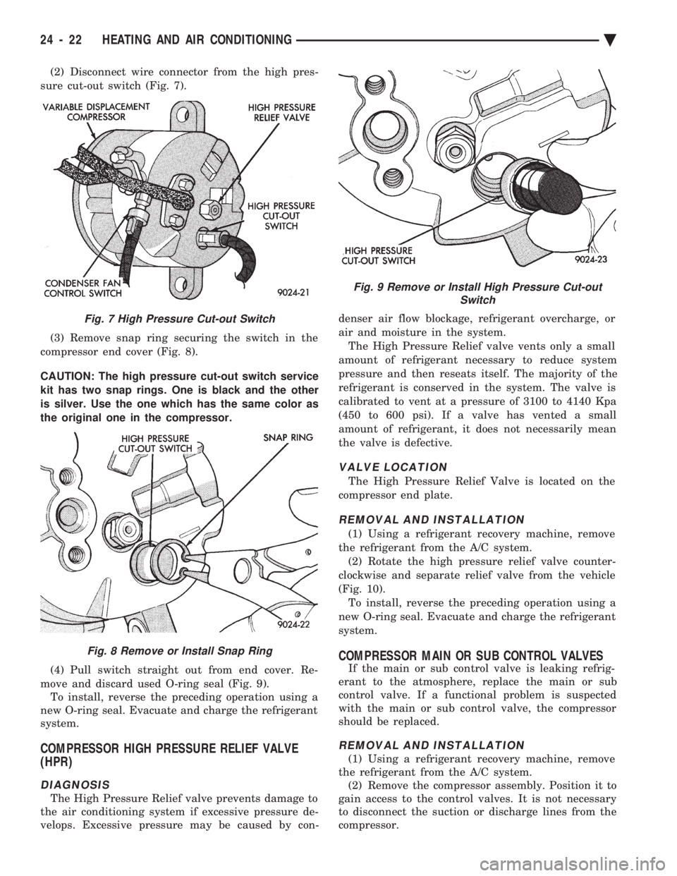
(2) Disconnect wire connector from the high pres-
sure cut-out switch (Fig. 7).
(3) Remove snap ring securing the switch in the
compressor end cover (Fig. 8).
CAUTION: The high pressure cut-out switch service
kit has two snap rings. One is black and the other
is silver. Use the one which has the same color as
the original one in the compressor.
(4) Pull switch straight out from end cover. Re-
move and discard used O-ring seal (Fig. 9). To install, reverse the preceding operation using a
new O-ring seal. Evacuate and charge the refrigerant
system.
COMPRESSOR HIGH PRESSURE RELIEF VALVE
(HPR)
DIAGNOSIS
The High Pressure Relief valve prevents damage to
the air conditioning system if excessive pressure de-
velops. Excessive pressure may be caused by con- denser air flow blockage, refrigerant overcharge, or
air and moisture in the system.
The High Pressure Relief valve vents only a small
amount of refrigerant necessary to reduce system
pressure and then reseats itself. The majority of the
refrigerant is conserved in the system. The valve is
calibrated to vent at a pressure of 3100 to 4140 Kpa
(450 to 600 psi). If a valve has vented a small
amount of refrigerant, it does not necessarily mean
the valve is defective.
VALVE LOCATION
The High Pressure Relief Valve is located on the
compressor end plate.
REMOVAL AND INSTALLATION
(1) Using a refrigerant recovery machine, remove
the refrigerant from the A/C system. (2) Rotate the high pressure relief valve counter-
clockwise and separate relief valve from the vehicle
(Fig. 10). To install, reverse the preceding operation using a
new O-ring seal. Evacuate and charge the refrigerant
system.
COMPRESSOR MAIN OR SUB CONTROL VALVES
If the main or sub control valve is leaking refrig-
erant to the atmosphere, replace the main or sub
control valve. If a functional problem is suspected
with the main or sub control valve, the compressor
should be replaced.
REMOVAL AND INSTALLATION
(1) Using a refrigerant recovery machine, remove
the refrigerant from the A/C system. (2) Remove the compressor assembly. Position it to
gain access to the control valves. It is not necessary
to disconnect the suction or discharge lines from the
compressor.
Fig. 7 High Pressure Cut-out Switch
Fig. 8 Remove or Install Snap Ring
Fig. 9 Remove or Install High Pressure Cut-out Switch
24 - 22 HEATING AND AIR CONDITIONING Ä
Page 2334 of 2438
CAUTION: Refer to Oil Level in the Refrigerant Ser-
vice Procedures section for further details. (13) Install refrigeration oil (500 SUS) into the
compressor through the suction port. (14) Check compressor operation for smoothness by
rotating crankshaft at least five full revolutions. (15) Check front housing clutch coil alignment pin
for proper installation. (16) Install clutch assembly.
(17) Install compressor.
(18) Evacuate and charge refrigerant system.
COMPRESSOR HIGH-PRESSURE RELIEF VALVE
The high pressure relief valve vents only a small
amount of refrigerant necessary to reduce system
pressure and then reseats itself. The majority of the
refrigerant is conserved in the system. The valve is
calibrated to vent at a pressure of 3100 to 4140 Kpa
(450 to 600 psi). If a valve has vented a small amount of refrigerant, it does not necessarily mean
the valve is defective.
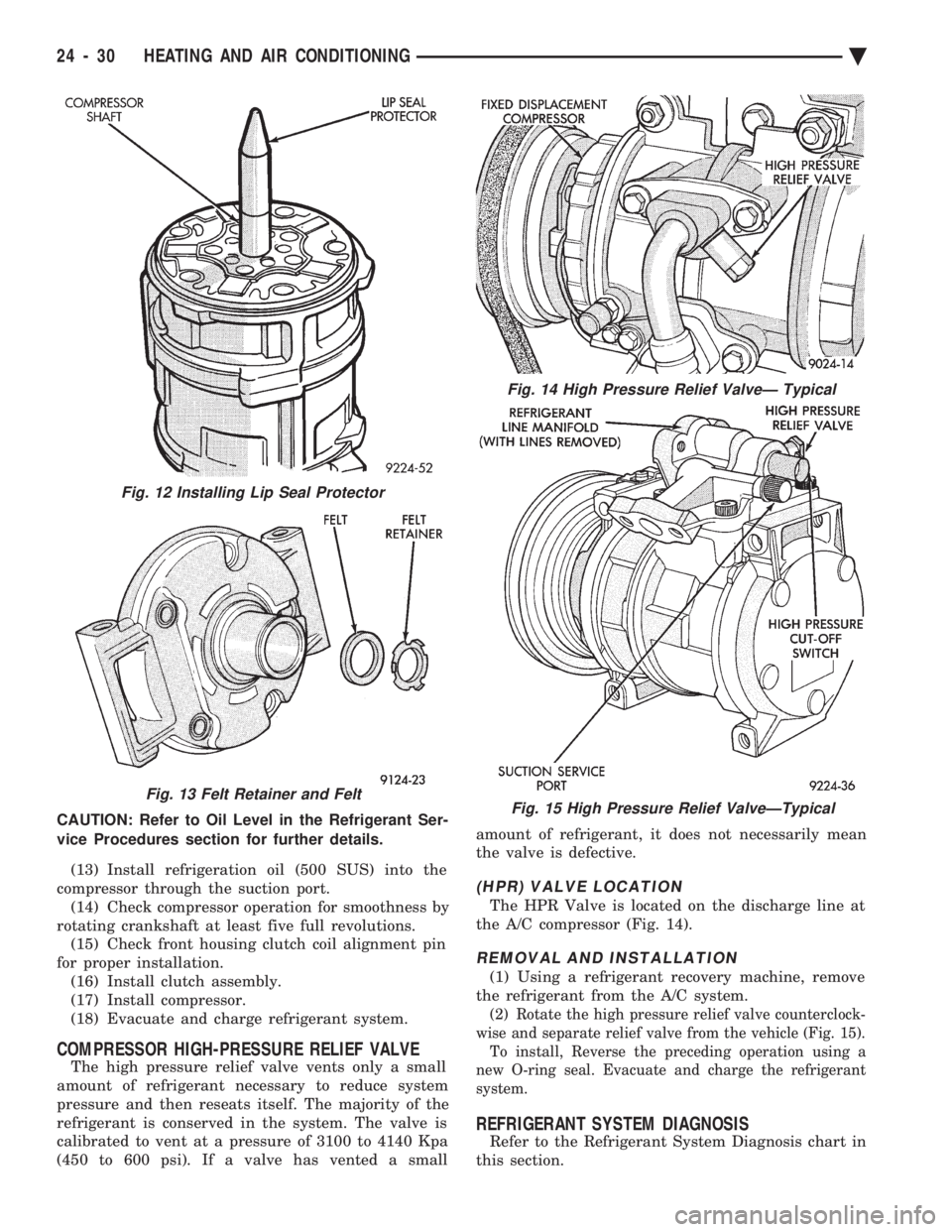
(HPR) VALVE LOCATION
The HPR Valve is located on the discharge line at
the A/C compressor (Fig. 14).
REMOVAL AND INSTALLATION
(1) Using a refrigerant recovery machine, remove
the refrigerant from the A/C system.
(2) Rotate the high pressure relief valve counterclock-
wise and separate relief valve from the vehicle (Fig. 15). To install, Reverse the preceding operation using a
new O-ring seal. Evacuate and charge the refrigerant
system.
REFRIGERANT SYSTEM DIAGNOSIS
Refer to the Refrigerant System Diagnosis chart in
this section.
Fig. 13 Felt Retainer and Felt
Fig. 14 High Pressure Relief ValveÐ Typical
Fig. 15 High Pressure Relief ValveÐTypical
Fig. 12 Installing Lip Seal Protector
24 - 30 HEATING AND AIR CONDITIONING Ä
Page 2342 of 2438
FIXED DISPLACEMENT COMPRESSORÐMODEL SD709P INDEX
page page
Compressor ............................. 38
Compressor Clutch/Coil Assembly ............ 38
Compressor Shaft Seal .................... 41 Cylinder Head/Valve Plate
.................. 44
Description ............................. 38
Refrigerant System Diagnosis ............... 45
DESCRIPTION
The Sanden compressor is a 7 piston design. Sys-
tem lubrication is provided by 135 ml 615 ml (4.6 oz.
6 0.5 oz.) of 500 viscosity refrigerant oil.
The clutch used on the compressor consists of 3 ba-
sic components:
² The pulley
² Front plate
² Field coil
The pulley and field coil are attached to the front
head of the compressor with tapered snap rings. The
hub is keyed to the compressor shaft and is retained
on the shaft with a self-locking nut. Special service
tools are required to remove and install the clutch
plate on the compressor shaft.
COMPRESSOR
The A/C compressor may be removed and posi-
tioned without discharging the refrigerant system.
Discharging is not necessary if removing the A/C
compressor clutch/coil assembly, engine, cylinder
head, or generator.
WARNING: REFRIGERANT PRESSURES REMAIN
HIGH EVEN THOUGH THE ENGINE MAY BE
TURNED OFF. BEFORE REMOVING A FULLY
CHARGED COMPRESSOR, REVIEW THE SAFETY
PRECAUTIONS AND WARNINGS SECTION IN THIS
GROUP. DO NOT TWIST OR KINK THE REFRIGER-
ANT LINES WHEN REMOVING A FULLY CHARGED
COMPRESSOR. SAFETY GLASSES MUST BE
WORN.
REMOVAL
(1) Disconnect negative cable from battery.
(2) Loosen and remove drive belts (refer to group
7, Cooling System) and disconnect compressor clutch
wire lead. (3) Remove refrigerant lines from compressor (if
necessary). (4) Remove compressor attaching nuts and bolts.
(5) Remove compressor. If refrigerant lines were
not removed, lift compressor/clutch assembly and tie
it to a suitable component. To install, reverse the removal procedure.
COMPRESSOR CLUTCH/COIL ASSEMBLY
The magnetic clutch consists of a stationary elec-
tro-magnetic coil and a rotating pulley and plate as-
sembly. The electromagnetic coil is retained on the com-
pressor with a snap ring and is dimpled to maintain
its position. The pulley and plate assembly are mounted on the
compressor shaft. When the compressor is not in operation, the pul-
ley free wheels on the clutch hub bearing. When the
coil is energized the plate is magnetically engaged
with the pulley and turns the compressor shaft.
REMOVAL
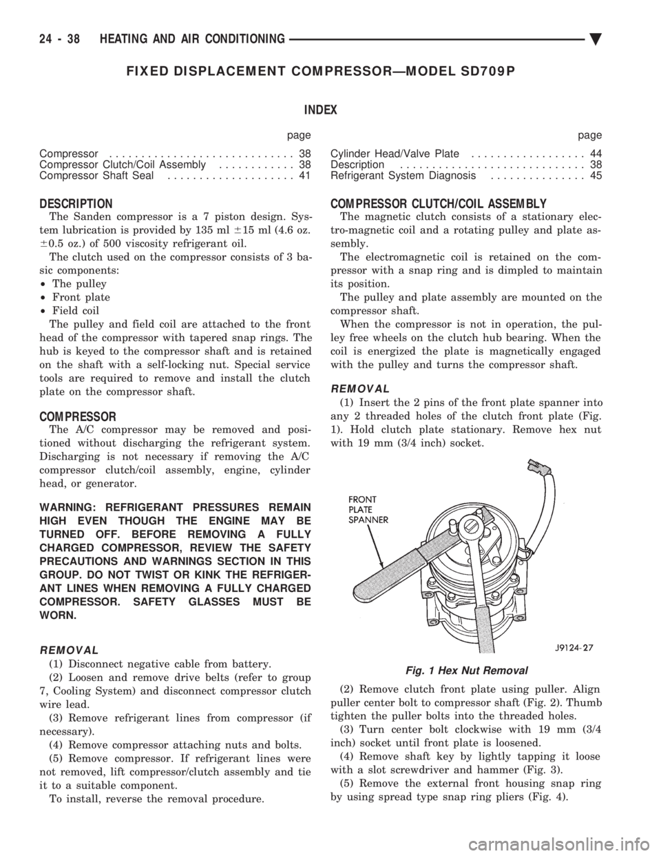
(1) Insert the 2 pins of the front plate spanner into
any 2 threaded holes of the clutch front plate (Fig.
1). Hold clutch plate stationary. Remove hex nut
with 19 mm (3/4 inch) socket.
(2) Remove clutch front plate using puller. Align
puller center bolt to compressor shaft (Fig. 2). Thumb
tighten the puller bolts into the threaded holes. (3) Turn center bolt clockwise with 19 mm (3/4
inch) socket until front plate is loosened. (4) Remove shaft key by lightly tapping it loose
with a slot screwdriver and hammer (Fig. 3). (5) Remove the external front housing snap ring
by using spread type snap ring pliers (Fig. 4).
Fig. 1 Hex Nut Removal
24 - 38 HEATING AND AIR CONDITIONING Ä
Page 2343 of 2438
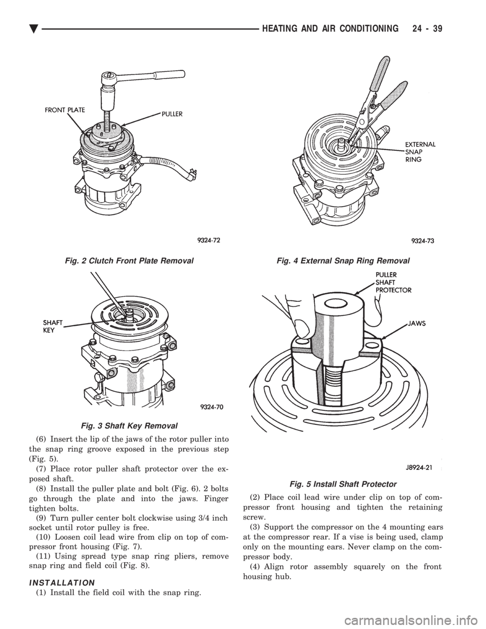
(6) Insert the lip of the jaws of the rotor puller into
the snap ring groove exposed in the previous step
(Fig. 5). (7) Place rotor puller shaft protector over the ex-
posed shaft. (8) Install the puller plate and bolt (Fig. 6). 2 bolts
go through the plate and into the jaws. Finger
tighten bolts. (9) Turn puller center bolt clockwise using 3/4 inch
socket until rotor pulley is free. (10) Loosen coil lead wire from clip on top of com-
pressor front housing (Fig. 7). (11) Using spread type snap ring pliers, remove
snap ring and field coil (Fig. 8).
INSTALLATION
(1) Install the field coil with the snap ring. (2) Place coil lead wire under clip on top of com-
pressor front housing and tighten the retaining
screw. (3) Support the compressor on the 4 mounting ears
at the compressor rear. If a vise is being used, clamp
only on the mounting ears. Never clamp on the com-
pressor body. (4) Align rotor assembly squarely on the front
housing hub.
Fig. 2 Clutch Front Plate Removal
Fig. 3 Shaft Key Removal
Fig. 4 External Snap Ring Removal
Fig. 5 Install Shaft Protector
Ä HEATING AND AIR CONDITIONING 24 - 39
Page 2345 of 2438
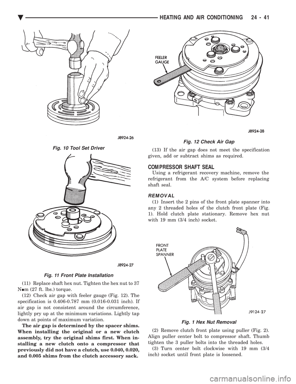
(11) Replace shaft hex nut. Tighten the hex nut to 37
N Im (27 ft. lbs.) torque.
(12) Check air gap with feeler gauge (Fig. 12). The
specification is 0.406-0.787 mm (0.016-0.031 inch). If
air gap is not consistent around the circumference,
lightly pry up at the minimum variations. Lightly tap
down at points of maximum variation. The air gap is determined by the spacer shims.
When installing the original or a new clutch
assembly, try the original shims first. When in-
stalling a new clutch onto a compressor that
previously did not have a clutch, use 0.040, 0.020,
and 0.005 shims from the clutch accessory sack. (13) If the air gap does not meet the specification
given, add or subtract shims as required.
COMPRESSOR SHAFT SEAL
Using a refrigerant recovery machine, remove the
refrigerant from the A/C system before replacing
shaft seal.
REMOVAL
(1) Insert the 2 pins of the front plate spanner into
any 2 threaded holes of the clutch front plate (Fig.
1). Hold clutch plate stationary. Remove hex nut
with 19 mm (3/4 inch) socket.
(2) Remove clutch front plate using puller (Fig. 2).
Align puller center bolt to compressor shaft. Thumb
tighten the 3 puller bolts into the threaded holes. (3) Turn center bolt clockwise with 19 mm (3/4
inch) socket until front plate is loosened.
Fig. 12 Check Air Gap
Fig. 1 Hex Nut Removal
Fig. 10 Tool Set Driver
Fig. 11 Front Plate Installation
Ä HEATING AND AIR CONDITIONING 24 - 41
Page 2352 of 2438
WARNING: AVOID RADIATOR/CONDENSER FAN
BLADES WHEN WORKING IN THE RADIATOR
AREA. FAN IS CONTROLLED BY TEMPERATURE
AND CAN START ANY TIME IGNITION IS ON. PER-
SONAL INJURY CAN RESULT.
(1) Disconnect fan control switch wire connector.
(2) Using a suitable jumper wire, jump across ter-
minals in wire connector. (3) Connect a suitable continuity tester across fan
control switch terminals. (4) Start engine and set idle at 1300 rpm. The ra-
diator fan should run constantly. (5) Set the A/C controls to A/C and high blower.
(6) If the high pressure gauge reads below 1102
kPa (160 psi) there should be no continuity across
the switch terminals.
CAUTION: Do not allow engine to overheat when ra-
diator air flow is blocked.
(7) Block radiator air flow with a suitable cover to
increase the high side pressure to at least 1585 kPa
(230 psi). Electrical continuity should be detected
across the fan control switch terminals. (8) Remove cover from front of vehicle to allow
high side pressure to decrease. When pressure drops
below 1102 kPa (160 psi), continuity should cease. If fan control switch is defective, replace it.
REMOVAL AND INSTALLATION
CAUTION: Refrigerant removal is not necessary
when removing the Condenser Fan Control Switch.
However, a small amount of refrigerant will vent
from the switch port. Review the refrigerant han-
dling section of Safety Precautions and Warnings in
the General Information section of this Group.
(1) Disconnect wire connector from condenser fan
control switch. (2) Loosen and quickly rotate the switch counter-
clockwise and separate from the high pressure line
switch port. To install, reverse the preceding operation.
DIFFERENTIAL PRESSURE CUT-OUT SWITCH
DIAGNOSIS
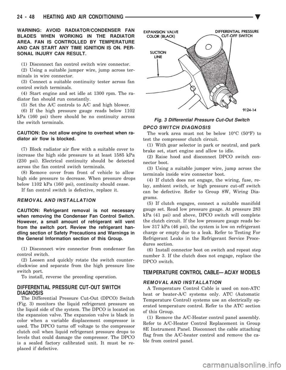
The Differential Pressure Cut-Out (DPCO) Switch
(Fig. 3) monitors the liquid refrigerant pressure on
the liquid side of the system. The DPCO is located on
the expansion valve. The expansion valve is black in
color when a variable displacement compressor is
used. The DPCO turns off voltage to the compressor
clutch coil when liquid refrigerant pressure drops to
levels that could damage the compressor. The DPCO
is a sealed factory calibrated unit. It must be re-
placed if defective.
DPCO SWITCH DIAGNOSIS
The work area must not be below 10ÉC (50ÉF) to
test the compressor clutch circuit. (1) With gear selector in park or neutral, and park
brake set, start engine and allow to idle. (2) Raise hood and disconnect DPCO switch con-
nector boot. (3) Using a suitable jumper wire, jump across the
terminals inside wire connector boot. (4) If clutch does not engage, the wiring, fuse, re-
lay, ambient switch, or high pressure cut-off switch
can be defective. Refer to Group 8W, Wiring Dia-
grams. (5) If clutch engages, connect a suitable manifold
gauge set. Read low pressure gauge. At pressure 283
kPa (41 psi) and above, DPCO switch will complete
the clutch circuit. If the low pressure gauge reads be-
low 317 kPa (46 psi), the system is low on refrigerant
charge or empty due to a leak. Refer to Testing For
Refrigerant Leaks in the Refrigerant Service Proce-
dures section. (6) Install connector boot on switch and repeat step
number 3. If the clutch does not engage, replace the
DPCO switch.
TEMPERATURE CONTROL CABLEÐAC/AY MODELS
REMOVAL AND INSTALLATION
A Temperature Control Cable is used on non-ATC
heat or heater-A/C systems only. ATC (Automatic
Temperature Control) systems use an electrically op-
erated temperature control. Refer to the ATC section
of this Group. (1) Remove the A/C-Heater control panel assembly.
Refer to A/C-Heater Control Replacement in Group
8E Instrument Panel. Disconnect the cable attaching
flag from the A/C-heater control and remove the ca-
ble from control panel.
Fig. 3 Differential Pressure Cut-Out Switch
24 - 48 HEATING AND AIR CONDITIONING Ä