1993 CHEVROLET PLYMOUTH ACCLAIM clock
[x] Cancel search: clockPage 1613 of 2438
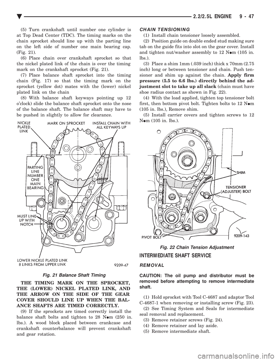
(5) Turn crankshaft until number one cylinder is
at Top Dead Center (TDC). The timing marks on the
chain sprocket should line up with the parting line
on the left side of number one main bearing cap.
(Fig. 21). (6) Place chain over crankshaft sprocket so that
the nickel plated link of the chain is over the timing
mark on the crankshaft sprocket (Fig. 21). (7) Place balance shaft sprocket into the timing
chain (Fig. 17) so that the timing mark on the
sprocket (yellow dot) mates with the (lower) nickel
plated link on the chain (8) With balance shaft keyways pointing up 12
o'clock) slide the balance shaft sprocket onto the nose
of the balance shaft. The balance shaft may have to
be pushed in slightly to allow for clearance.
THE TIMING MARK ON THE SPROCKET,
THE (LOWER) NICKEL PLATED LINK, AND
THE ARROW ON THE SIDE OF THE GEAR
COVER SHOULD LINE UP WHEN THE BAL-
ANCE SHAFTS ARE TIMED CORRECTLY. (9) If the sprockets are timed correctly install the
balance shaft bolts and tighten to 28 N Im (250 in.
lbs.). A wood block placed between crankcase and
crankshaft counterbalance will prevent crankshaft
and gear rotation.CHAIN TENSIONING
(1) Install chain tensioner loosely assembled.
(2) Position guide on double ended stud making sure
tab on the guide fits into slot on the gear cover. Install
and tighten nut/washer assembly to 12 N Im (105 in.
lbs.). (3) Place a shim 1mm (.039 inch) thick x 70mm (2.75
inch) long or between tensioner and chain. Push ten-
sioner and shim up against the chain. Apply firm
pressure (5.5 to 6.6 lbs.) directly behind the ad-
justment slot to take up all slack (chain must have
shoe radius contact as shown in Fig. 22). (4) With the load applied, tighten top tensioner bolt
first, then bottom pivot bolt. Tighten bolts to 12 N Im
(105 in. lbs.), Remove shim. (5) Install carrier covers and tighten screws to 12
N Im (105 in. lbs.).
INTERMEDIATE SHAFT SERVICE
REMOVAL
CAUTION: The oil pump and distributor must be
removed before attempting to remove intermediate
shaft.
(1) Hold sprocket with Tool C-4687 and adaptor Tool
C-4687-1 when removing or installing screw (Fig. 23). (2) See Timing System and Seals for intermediate
seal removal and replacement. (3) Remove retainer screws (Fig. 24).
(4) Remove retainer and lay aside.
(5) Remove intermediate shaft.Fig. 21 Balance Shaft Timing
Fig. 22 Chain Tension Adjustment
Ä 2.2/2.5L ENGINE 9 - 47
Page 1627 of 2438
(3) Oil Pressure: Curb Idle25 kPa (4 psi) mini-
mum 3000 RPM 170-550 kPa (25-80 psi).
OIL FILTER
ANTI-DRAIN BACK VALVE
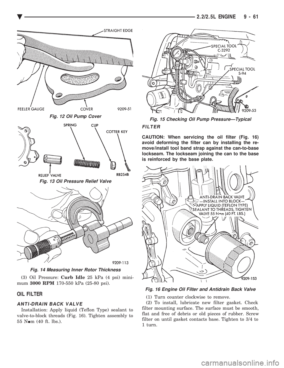
Installation: Apply liquid (Teflon Type) sealant to
valve-to-block threads (Fig. 16). Tighten assembly to
55 N Im (40 ft. lbs.).
FILTER
CAUTION: When servicing the oil filter (Fig. 16)
avoid deforming the filter can by installing the re-
move/install tool band strap against the can-to-base
lockseam. The lockseam joining the can to the base
is reinforced by the base plate.
(1) Turn counter clockwise to remove.
(2) To install, lubricate new filter gasket. Check
filter mounting surface. The surface must be smooth,
flat and free of debris or old pieces of rubber. Screw
filter on until gasket contacts base. Tighten to 3/4 to
1 turn.
Fig. 12 Oil Pump Cover
Fig. 13 Oil Pressure Relief Valve
Fig. 14 Measuring Inner Rotor Thickness
Fig. 15 Checking Oil Pump PressureÐTypical
Fig. 16 Engine Oil Filter and Antidrain Back Valve
Ä 2.2/2.5L ENGINE 9 - 61
Page 1636 of 2438
(c) Remove LEFT insulator through bolt from in-
side wheelhouse or insulator bracket to transmis-
sion screws.
(22) Remove engine.
INSTALLATION
(1) Attach hoist and lower engine into engine com-
partment. (2) Align engine mounts and install but do not
tighten until all mounting bolts have been installed.
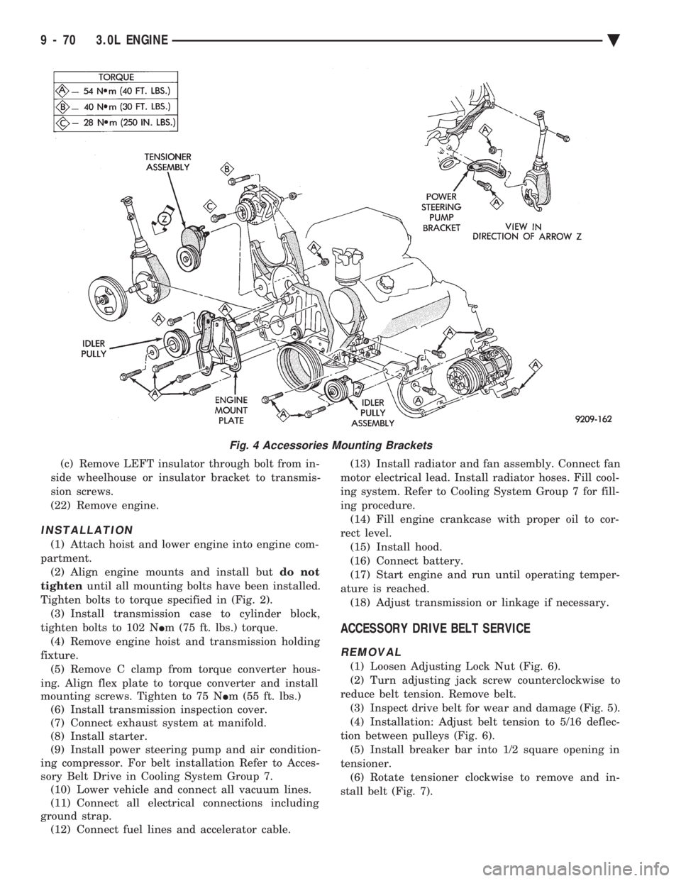
Tighten bolts to torque specified in (Fig. 2). (3) Install transmission case to cylinder block,
tighten bolts to 102 N Im (75 ft. lbs.) torque.
(4) Remove engine hoist and transmission holding
fixture. (5) Remove C clamp from torque converter hous-
ing. Align flex plate to torque converter and install
mounting screws. Tighten to 75 N Im (55 ft. lbs.)
(6) Install transmission inspection cover.
(7) Connect exhaust system at manifold.
(8) Install starter.
(9) Install power steering pump and air condition-
ing compressor. For belt installation Refer to Acces-
sory Belt Drive in Cooling System Group 7. (10) Lower vehicle and connect all vacuum lines.
(11) Connect all electrical connections including
ground strap. (12) Connect fuel lines and accelerator cable. (13) Install radiator and fan assembly. Connect fan
motor electrical lead. Install radiator hoses. Fill cool-
ing system. Refer to Cooling System Group 7 for fill-
ing procedure. (14) Fill engine crankcase with proper oil to cor-
rect level. (15) Install hood.
(16) Connect battery.
(17) Start engine and run until operating temper-
ature is reached. (18) Adjust transmission or linkage if necessary.
ACCESSORY DRIVE BELT SERVICE
REMOVAL
(1) Loosen Adjusting Lock Nut (Fig. 6).
(2) Turn adjusting jack screw counterclockwise to
reduce belt tension. Remove belt. (3) Inspect drive belt for wear and damage (Fig. 5).
(4) Installation: Adjust belt tension to 5/16 deflec-
tion between pulleys (Fig. 6). (5) Install breaker bar into 1/2 square opening in
tensioner. (6) Rotate tensioner clockwise to remove and in-
stall belt (Fig. 7).
Fig. 4 Accessories Mounting Brackets
9 - 70 3.0L ENGINE Ä
Page 1640 of 2438
INSTALLATION
(1) Place camshaft sprocket on camshaft.
(2) Install bolt and washer to camshaft. Using
Spanner Tool MB990775 hold camshaft sprocket and
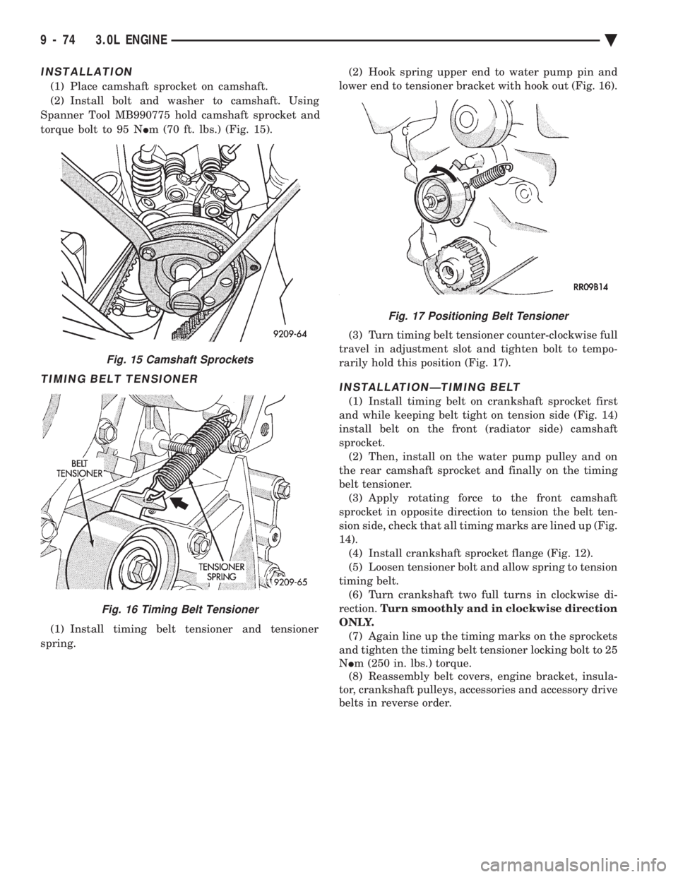
torque bolt to 95 N Im (70 ft. lbs.) (Fig. 15).
TIMING BELT TENSIONER
(1) Install timing belt tensioner and tensioner
spring. (2) Hook spring upper end to water pump pin and
lower end to tensioner bracket with hook out (Fig. 16).
(3) Turn timing belt tensioner counter-clockwise full
travel in adjustment slot and tighten bolt to tempo-
rarily hold this position (Fig. 17).
INSTALLATIONÐTIMING BELT
(1) Install timing belt on crankshaft sprocket first
and while keeping belt tight on tension side (Fig. 14)
install belt on the front (radiator side) camshaft
sprocket. (2) Then, install on the water pump pulley and on
the rear camshaft sprocket and finally on the timing
belt tensioner. (3) Apply rotating force to the front camshaft
sprocket in opposite direction to tension the belt ten-
sion side, check that all timing marks are lined up (Fig.
14). (4) Install crankshaft sprocket flange (Fig. 12).
(5) Loosen tensioner bolt and allow spring to tension
timing belt. (6) Turn crankshaft two full turns in clockwise di-
rection. Turn smoothly and in clockwise direction
ONLY. (7) Again line up the timing marks on the sprockets
and tighten the timing belt tensioner locking bolt to 25
N Im (250 in. lbs.) torque.
(8) Reassembly belt covers, engine bracket, insula-
tor, crankshaft pulleys, accessories and accessory drive
belts in reverse order.
Fig. 15 Camshaft Sprockets
Fig. 16 Timing Belt Tensioner
Fig. 17 Positioning Belt Tensioner
9 - 74 3.0L ENGINE Ä
Page 1660 of 2438
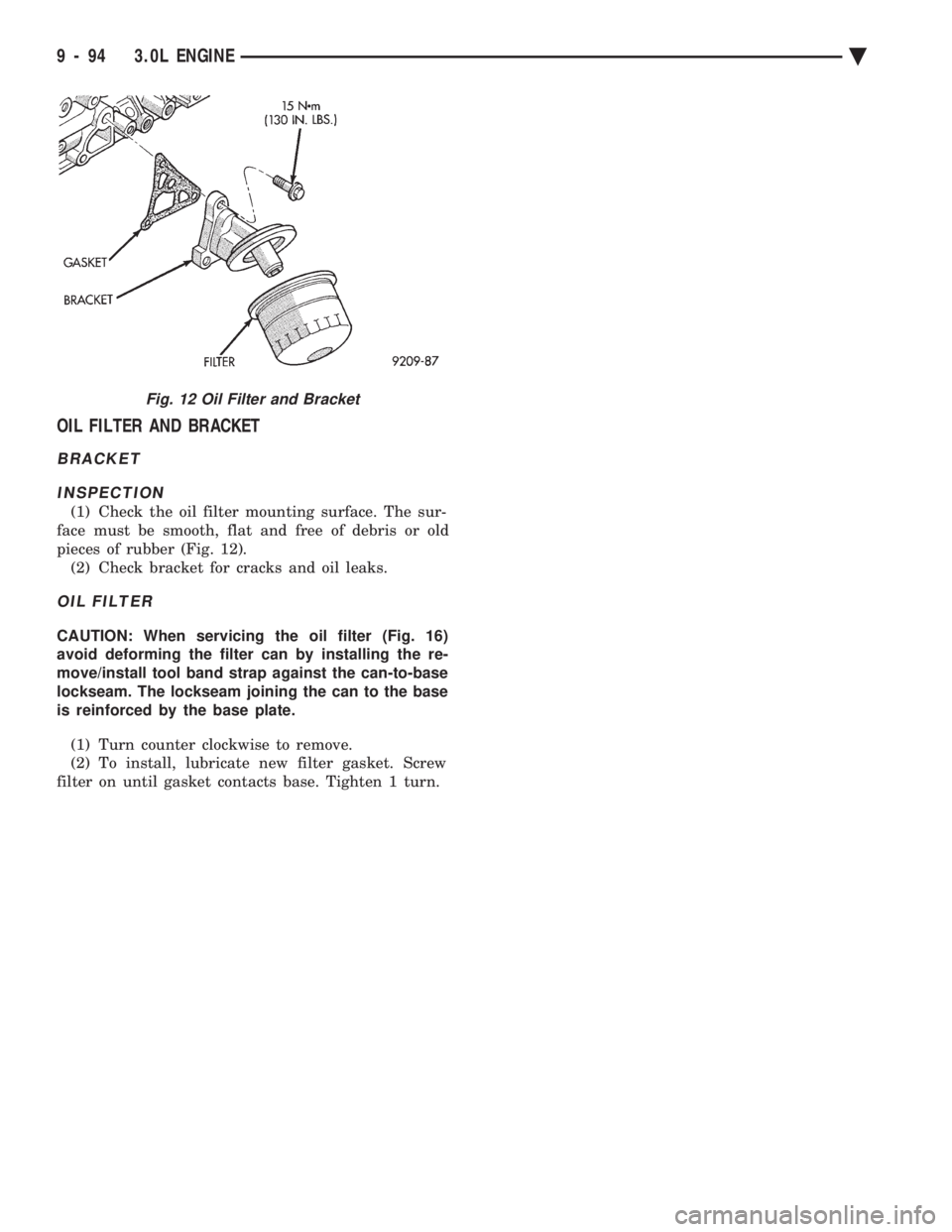
OIL FILTER AND BRACKET
BRACKET INSPECTION
(1) Check the oil filter mounting surface. The sur-
face must be smooth, flat and free of debris or old
pieces of rubber (Fig. 12). (2) Check bracket for cracks and oil leaks.
OIL FILTER
CAUTION: When servicing the oil filter (Fig. 16)
avoid deforming the filter can by installing the re-
move/install tool band strap against the can-to-base
lockseam. The lockseam joining the can to the base
is reinforced by the base plate.
(1) Turn counter clockwise to remove.
(2) To install, lubricate new filter gasket. Screw
filter on until gasket contacts base. Tighten 1 turn.
Fig. 12 Oil Filter and Bracket
9 - 94 3.0L ENGINE Ä
Page 1675 of 2438
(2) Clean varnish deposits from inside of tappet
body above plunger cap. (3) Invert tappet body and remove plunger cap,
plunger, flat or ball check valve, check valve spring,
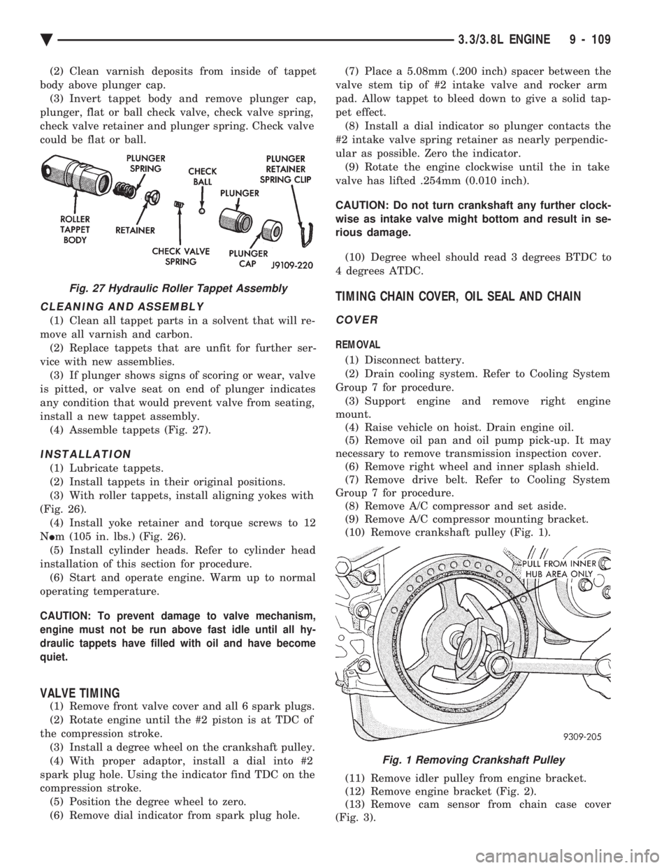
check valve retainer and plunger spring. Check valve
could be flat or ball.
CLEANING AND ASSEMBLY
(1) Clean all tappet parts in a solvent that will re-
move all varnish and carbon. (2) Replace tappets that are unfit for further ser-
vice with new assemblies. (3) If plunger shows signs of scoring or wear, valve
is pitted, or valve seat on end of plunger indicates
any condition that would prevent valve from seating,
install a new tappet assembly. (4) Assemble tappets (Fig. 27).
INSTALLATION
(1) Lubricate tappets.
(2) Install tappets in their original positions.
(3) With roller tappets, install aligning yokes with
(Fig. 26). (4) Install yoke retainer and torque screws to 12
N Im (105 in. lbs.) (Fig. 26).
(5) Install cylinder heads. Refer to cylinder head
installation of this section for procedure. (6) Start and operate engine. Warm up to normal
operating temperature.
CAUTION: To prevent damage to valve mechanism,
engine must not be run above fast idle until all hy-
draulic tappets have filled with oil and have become
quiet.
VALVE TIMING
(1) Remove front valve cover and all 6 spark plugs.
(2) Rotate engine until the #2 piston is at TDC of
the compression stroke. (3) Install a degree wheel on the crankshaft pulley.
(4) With proper adaptor, install a dial into #2
spark plug hole. Using the indicator find TDC on the
compression stroke. (5) Position the degree wheel to zero.
(6) Remove dial indicator from spark plug hole. (7) Place a 5.08mm (.200 inch) spacer between the
valve stem tip of #2 intake valve and rocker arm
pad. Allow tappet to bleed down to give a solid tap-
pet effect. (8) Install a dial indicator so plunger contacts the
#2 intake valve spring retainer as nearly perpendic-
ular as possible. Zero the indicator. (9) Rotate the engine clockwise until the in take
valve has lifted .254mm (0.010 inch).
CAUTION: Do not turn crankshaft any further clock-
wise as intake valve might bottom and result in se-
rious damage.
(10) Degree wheel should read 3 degrees BTDC to
4 degrees ATDC.
TIMING CHAIN COVER, OIL SEAL AND CHAIN
COVER
REMOVAL
(1) Disconnect battery.
(2) Drain cooling system. Refer to Cooling System
Group 7 for procedure. (3) Support engine and remove right engine
mount. (4) Raise vehicle on hoist. Drain engine oil.
(5) Remove oil pan and oil pump pick-up. It may
necessary to remove transmission inspection cover. (6) Remove right wheel and inner splash shield.
(7) Remove drive belt. Refer to Cooling System
Group 7 for procedure. (8) Remove A/C compressor and set aside.
(9) Remove A/C compressor mounting bracket.
(10) Remove crankshaft pulley (Fig. 1).
(11) Remove idler pulley from engine bracket.
(12) Remove engine bracket (Fig. 2).
(13) Remove cam sensor from chain case cover
(Fig. 3).
Fig. 27 Hydraulic Roller Tappet Assembly
Fig. 1 Removing Crankshaft Pulley
Ä 3.3/3.8L ENGINE 9 - 109
Page 1676 of 2438
(14) Remove chain case cover (Fig. 3).
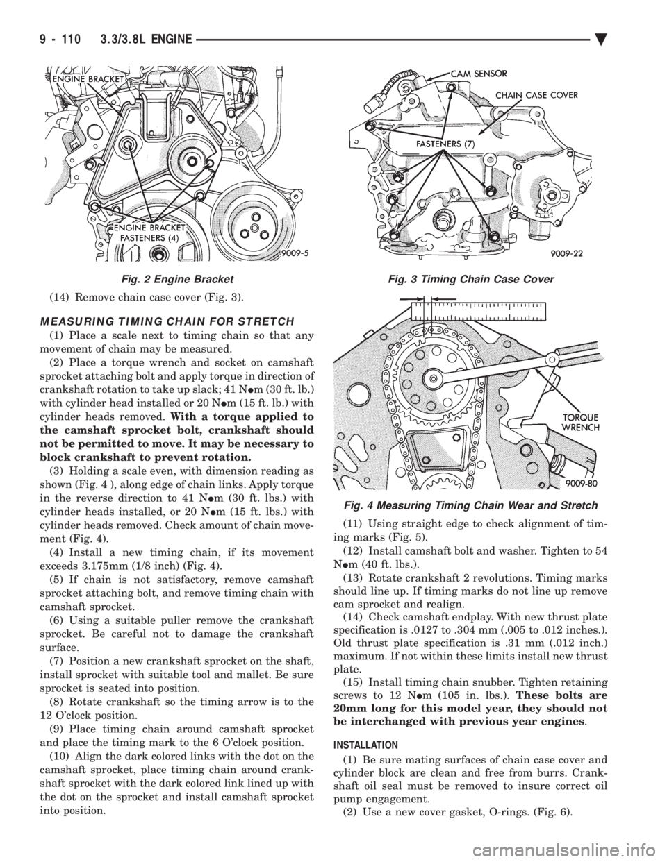
MEASURING TIMING CHAIN FOR STRETCH
(1) Place a scale next to timing chain so that any
movement of chain may be measured. (2) Place a torque wrench and socket on camshaft
sprocket attaching bolt and apply torque in direction of
crankshaft rotation to take up slack; 41 N Im (30 ft. lb.)
with cylinder head installed or 20 N Im (15 ft. lb.) with
cylinder heads removed. With a torque applied to
the camshaft sprocket bolt, crankshaft should
not be permitted to move. It may be necessary to
block crankshaft to prevent rotation. (3) Holding a scale even, with dimension reading as
shown (Fig. 4 ), along edge of chain links. Apply torque
in the reverse direction to 41 N Im (30 ft. lbs.) with
cylinder heads installed, or 20 N Im (15 ft. lbs.) with
cylinder heads removed. Check amount of chain move-
ment (Fig. 4). (4) Install a new timing chain, if its movement
exceeds 3.175mm (1/8 inch) (Fig. 4). (5) If chain is not satisfactory, remove camshaft
sprocket attaching bolt, and remove timing chain with
camshaft sprocket. (6) Using a suitable puller remove the crankshaft
sprocket. Be careful not to damage the crankshaft
surface. (7) Position a new crankshaft sprocket on the shaft,
install sprocket with suitable tool and mallet. Be sure
sprocket is seated into position. (8) Rotate crankshaft so the timing arrow is to the
12 O'clock position. (9) Place timing chain around camshaft sprocket
and place the timing mark to the 6 O'clock position. (10) Align the dark colored links with the dot on the
camshaft sprocket, place timing chain around crank-
shaft sprocket with the dark colored link lined up with
the dot on the sprocket and install camshaft sprocket
into position. (11) Using straight edge to check alignment of tim-
ing marks (Fig. 5). (12) Install camshaft bolt and washer. Tighten to 54
N Im (40 ft. lbs.).
(13) Rotate crankshaft 2 revolutions. Timing marks
should line up. If timing marks do not line up remove
cam sprocket and realign. (14) Check camshaft endplay. With new thrust plate
specification is .0127 to .304 mm (.005 to .012 inches.).
Old thrust plate specification is .31 mm (.012 inch.)
maximum. If not within these limits install new thrust
plate. (15) Install timing chain snubber. Tighten retaining
screws to 12 N Im (105 in. lbs.). These bolts are
20mm long for this model year, they should not
be interchanged with previous year engines .
INSTALLATION (1) Be sure mating surfaces of chain case cover and
cylinder block are clean and free from burrs. Crank-
shaft oil seal must be removed to insure correct oil
pump engagement. (2) Use a new cover gasket, O-rings. (Fig. 6).
Fig. 3 Timing Chain Case Cover
Fig. 4 Measuring Timing Chain Wear and Stretch
Fig. 2 Engine Bracket
9 - 110 3.3/3.8L ENGINE Ä
Page 1678 of 2438
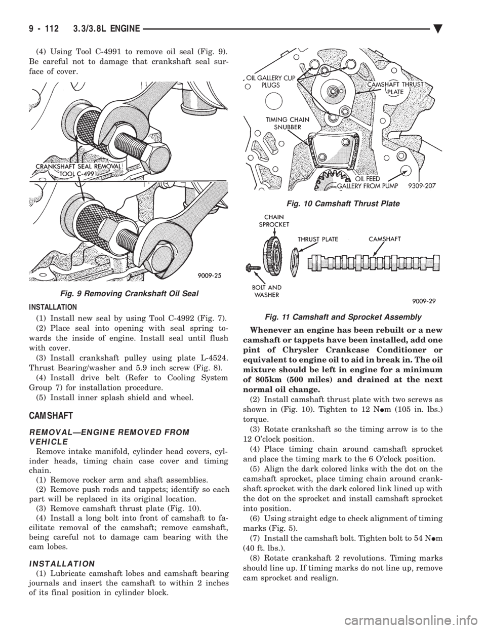
(4) Using Tool C-4991 to remove oil seal (Fig. 9).
Be careful not to damage that crankshaft seal sur-
face of cover.
INSTALLATION (1) Install new seal by using Tool C-4992 (Fig. 7).
(2) Place seal into opening with seal spring to-
wards the inside of engine. Install seal until flush
with cover. (3) Install crankshaft pulley using plate L-4524.
Thrust Bearing/washer and 5.9 inch screw (Fig. 8). (4) Install drive belt (Refer to Cooling System
Group 7) for installation procedure. (5) Install inner splash shield and wheel.
CAMSHAFT
REMOVALÐENGINE REMOVED FROM VEHICLE
Remove intake manifold, cylinder head covers, cyl-
inder heads, timing chain case cover and timing
chain. (1) Remove rocker arm and shaft assemblies.
(2) Remove push rods and tappets; identify so each
part will be replaced in its original location. (3) Remove camshaft thrust plate (Fig. 10).
(4) Install a long bolt into front of camshaft to fa-
cilitate removal of the camshaft; remove camshaft,
being careful not to damage cam bearing with the
cam lobes.
INSTALLATION
(1) Lubricate camshaft lobes and camshaft bearing
journals and insert the camshaft to within 2 inches
of its final position in cylinder block. Whenever an engine has been rebuilt or a new
camshaft or tappets have been installed, add one
pint of Chrysler Crankcase Conditioner or
equivalent to engine oil to aid in break in. The oil
mixture should be left in engine for a minimum
of 805km (500 miles) and drained at the next
normal oil change. (2) Install camshaft thrust plate with two screws as
shown in (Fig. 10). Tighten to 12 N Im (105 in. lbs.)
torque. (3) Rotate crankshaft so the timing arrow is to the
12 O'clock position. (4) Place timing chain around camshaft sprocket
and place the timing mark to the 6 O'clock position. (5) Align the dark colored links with the dot on the
camshaft sprocket, place timing chain around crank-
shaft sprocket with the dark colored link lined up with
the dot on the sprocket and install camshaft sprocket
into position. (6) Using straight edge to check alignment of timing
marks (Fig. 5). (7) Install the camshaft bolt. Tighten bolt to 54 N Im
(40 ft. lbs.). (8) Rotate crankshaft 2 revolutions. Timing marks
should line up. If timing marks do not line up, remove
cam sprocket and realign.
Fig. 9 Removing Crankshaft Oil Seal
Fig. 10 Camshaft Thrust Plate
Fig. 11 Camshaft and Sprocket Assembly
9 - 112 3.3/3.8L ENGINE Ä