1993 CHEVROLET PLYMOUTH ACCLAIM clock
[x] Cancel search: clockPage 1685 of 2438
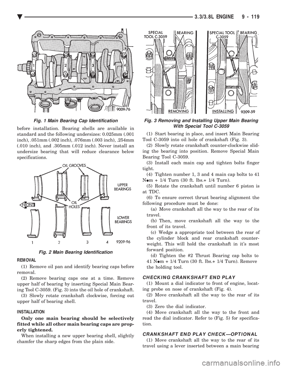
before installation. Bearing shells are available in
standard and the following undersizes: 0.025mm (.001
inch), .051mm (.002 inch), .076mm (.003 inch), .254mm
(.010 inch), and .305mm (.012 inch). Never install an
undersize bearing that will reduce clearance below
specifications.
REMOVAL (1) Remove oil pan and identify bearing caps before
removal. (2) Remove bearing caps one at a time. Remove
upper half of bearing by inserting Special Main Bear-
ing Tool C-3059. (Fig. 3) into the oil hole of crankshaft. (3) Slowly rotate crankshaft clockwise, forcing out
upper half of bearing shell.
INSTALLATION Only one main bearing should be selectively
fitted while all other main bearing caps are prop-
erly tightened. When installing a new upper bearing shell, slightly
chamfer the sharp edges from the plain side. (1) Start bearing in place, and insert Main Bearing
Tool C-3059 into oil hole of crankshaft (Fig. 3). (2) Slowly rotate crankshaft counter-clockwise slid-
ing the bearing into position. Remove Special Main
Bearing Tool C-3059. (3) Install each main cap and tighten bolts finger
tight. (4) Tighten number 1, 3 and 4 main cap bolts to 41
N Im + 1/4 Turn (30 ft. lbs.+ 1/4 Turn).
(5) Rotate the crankshaft until number 6 piston is
at TDC. (6) To ensure correct thrust bearing alignment the
following procedure must be done: (a) Move crankshaft all the way to the rear of its
travel. (b) Then, move crankshaft all the way to the
front of its travel. (c) Wedge a appropriate tool between the rear of
the cylinder block and rear crankshaft counter-
weight. This will hold the crankshaft in it's most
forward position. (d) Tighten the #2 Thrust Bearing cap bolts to
41 N Im + 1/4 Turn (30 ft. lbs.+ 1/4 Turn). Remove
the holding tool.
CHECKING CRANKSHAFT END PLAY
(1) Mount a dial indicator to front of engine, locat-
ing probe on nose of crankshaft (Fig. 4). (2) Move crankshaft all the way to the rear of its
travel. (3) Zero the dial indicator.
(4) Move crankshaft all the way to the front and
read the dial indicator. Refer to (Fig. 5) for specifica-
tion.
CRANKSHAFT END PLAY CHECKÐOPTIONAL
(1) Move crankshaft all the way to the rear of its
travel using a lever inserted between a main bearing
Fig. 3 Removing and Installing Upper Main Bearing With Special Tool C-3059Fig. 1 Main Bearing Cap Identification
Fig. 2 Main Bearing Identification
Ä 3.3/3.8L ENGINE 9 - 119
Page 1748 of 2438
CAUTION: When using the ASD Fuel System Test,
the Auto Shutdown (ASD) Relay remains energized
for either 7 minutes, until the test is stopped, or un-
til the ignition switch is turned to the Off position.
(4) Place the ignition key in the ON position. Us-
ing the DRBII scan tool, access ASD Fuel System
Test. The ASD Fuel System Test will activate the
fuel pump and pressurize the system. If the gauge reads the pressure shown in the Fuel
System Pressure chart, further testing is not re-
quired. If pressure is not correct, record the pressure
and remove gauge. If pressure is below specifications, proceed to Fuel
System Pressure Below Specifications . If pressure
is above specifications, proceed to Fuel System
Pressure Above Specifications .
Fuel System Pressure Below Specifications
If the fuel pressure reading in step (4) was below
specifications, test the system according to the fol-
lowing procedure.
WARNING: RELEASE FUEL SYSTEM PRESSURE
BEFORE DISCONNECTING A FUEL SYSTEM HOSE
OR COMPONENT.
(a) Perform Fuel Pressure Release procedure.
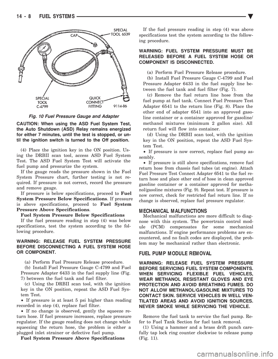
(b) Install Fuel Pressure Gauge C-4799 and Fuel
Pressure Adapter 6433 in the fuel supply line (Fig.
7) between the fuel tank and fuel filter. (c) Using the DRBII scan tool, with the ignition
key in the ON position, repeat the ASD Fuel Sys-
tem Test.
² If pressure is at least 5 psi higher than reading
recorded in step (4), replace fuel filter. ² If no change is observed, gently the squeeze re-
turn hose. If fuel pressure increases, replace pressure
regulator. If the gauge reading does not change while
squeezing the return hose, the problem is either a
plugged inlet strainer or defective fuel pump. Fuel System Pressure Above Specifications If the fuel pressure reading in step (4) was above
specifications test the system according to the follow-
ing procedure.
WARNING: FUEL SYSTEM PRESSURE MUST BE
RELEASED BEFORE A FUEL SYSTEM HOSE OR
COMPONENT IS DISCONNECTED.
(a) Perform Fuel Pressure Release procedure.
(b) Install Fuel Pressure Gauge C-4799 and Fuel
Pressure Adapter 6433 in the fuel supply line be-
tween the fuel tank and fuel filter (Fig. 7). (c) Remove the fuel return line hose from the
fuel pump at fuel tank. Connect Fuel Pressure Test
Adapter 6541 to the return line (Fig. 8). Place the
other end of adapter 6541 into an approved gaso-
line container or a container approved for gasoline/
methanol mixtures (minimum 2 gallon size). All
return fuel will flow into container. (d) Using the DRBII scan tool, with the ignition
key in the ON position, repeat the ASD Fuel Sys-
tem Test.
² If pressure is now correct, replace fuel pump as-
sembly. ²
If pressure is still above specifications, remove fuel
return hose from chassis fuel tubes (at engine). Attach
Fuel Pressure Test Connect Adapter 6541 to the fuel re-
turn hose and place other end of hose in clean approved
gasoline container or a container approved for metha-
nol/gasoline mixtures (Fig. 9). Repeat test. If pressure is
now correct, check for restricted fuel return line. If no
change is observed, replace fuel pressure regulator.
MECHANICAL MALFUNCTIONS
Mechanical malfunctions are more difficult to diag-
nose with this system. The powertrain control mod-
ule (PCM) compensates for some mechanical
malfunctions. If engine performance problems are en-
countered, and no fault codes are displayed, the prob-
lem may be mechanical rather than electronic.
FUEL PUMP MODULE REMOVAL
WARNING: RELEASE FUEL SYSTEM PRESSURE
BEFORE SERVICING FUEL SYSTEM COMPONENTS.
WHEN SERVICING FLEXIBLE FUEL VEHICLES,
WEAR METHANOL RESISTANT GLOVES AND EYE
PROTECTION AND AVOID BREATHING FUMES. DO
NOT ALLOW METHANOL/GASOLINE MIXTURES TO
CONTACT SKIN. SERVICE VEHICLES IN WELL VEN-
TILATED AREAS AND AVOID IGNITION SOURCES.
NEVER SMOKE WHILE SERVICING THE VEHICLE.
Remove the fuel tank to service the fuel pump. Re-
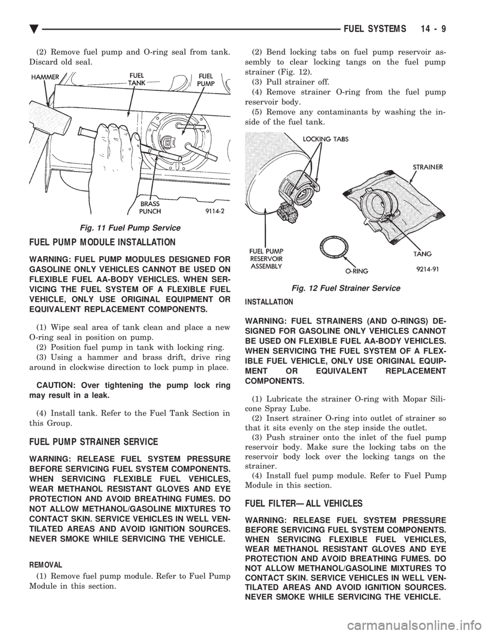
fer to Fuel Tank Section for fuel tank removal. (1) Using a hammer and a brass drift punch care-
fully tap lock ring counter clockwise to release pump
(Fig. 11).
Fig. 10 Fuel Pressure Gauge and Adapter
14 - 8 FUEL SYSTEMS Ä
Page 1749 of 2438
(2) Remove fuel pump and O-ring seal from tank.
Discard old seal.
FUEL PUMP MODULE INSTALLATION
WARNING: FUEL PUMP MODULES DESIGNED FOR
GASOLINE ONLY VEHICLES CANNOT BE USED ON
FLEXIBLE FUEL AA-BODY VEHICLES. WHEN SER-
VICING THE FUEL SYSTEM OF A FLEXIBLE FUEL
VEHICLE, ONLY USE ORIGINAL EQUIPMENT OR
EQUIVALENT REPLACEMENT COMPONENTS.
(1) Wipe seal area of tank clean and place a new
O-ring seal in position on pump. (2) Position fuel pump in tank with locking ring.
(3) Using a hammer and brass drift, drive ring
around in clockwise direction to lock pump in place.
CAUTION: Over tightening the pump lock ring
may result in a leak.
(4) Install tank. Refer to the Fuel Tank Section in
this Group.
FUEL PUMP STRAINER SERVICE
WARNING: RELEASE FUEL SYSTEM PRESSURE
BEFORE SERVICING FUEL SYSTEM COMPONENTS.
WHEN SERVICING FLEXIBLE FUEL VEHICLES,
WEAR METHANOL RESISTANT GLOVES AND EYE
PROTECTION AND AVOID BREATHING FUMES. DO
NOT ALLOW METHANOL/GASOLINE MIXTURES TO
CONTACT SKIN. SERVICE VEHICLES IN WELL VEN-
TILATED AREAS AND AVOID IGNITION SOURCES.
NEVER SMOKE WHILE SERVICING THE VEHICLE.
REMOVAL
(1) Remove fuel pump module. Refer to Fuel Pump
Module in this section. (2) Bend locking tabs on fuel pump reservoir as-
sembly to clear locking tangs on the fuel pump
strainer (Fig. 12). (3) Pull strainer off.
(4) Remove strainer O-ring from the fuel pump
reservoir body. (5) Remove any contaminants by washing the in-
side of the fuel tank.
INSTALLATION
WARNING: FUEL STRAINERS (AND O-RINGS) DE-
SIGNED FOR GASOLINE ONLY VEHICLES CANNOT
BE USED ON FLEXIBLE FUEL AA-BODY VEHICLES.
WHEN SERVICING THE FUEL SYSTEM OF A FLEX-
IBLE FUEL VEHICLE, ONLY USE ORIGINAL EQUIP-
MENT OR EQUIVALENT REPLACEMENT
COMPONENTS.
(1) Lubricate the strainer O-ring with Mopar Sili-
cone Spray Lube. (2) Insert strainer O-ring into outlet of strainer so
that it sits evenly on the step inside the outlet. (3) Push strainer onto the inlet of the fuel pump
reservoir body. Make sure the locking tabs on the
reservoir body lock over the locking tangs on the
strainer. (4) Install fuel pump module. Refer to Fuel Pump
Module in this section.
FUEL FILTERÐALL VEHICLES
WARNING: RELEASE FUEL SYSTEM PRESSURE
BEFORE SERVICING FUEL SYSTEM COMPONENTS.
WHEN SERVICING FLEXIBLE FUEL VEHICLES,
WEAR METHANOL RESISTANT GLOVES AND EYE
PROTECTION AND AVOID BREATHING FUMES. DO
NOT ALLOW METHANOL/GASOLINE MIXTURES TO
CONTACT SKIN. SERVICE VEHICLES IN WELL VEN-
TILATED AREAS AND AVOID IGNITION SOURCES.
NEVER SMOKE WHILE SERVICING THE VEHICLE.
Fig. 11 Fuel Pump Service
Fig. 12 Fuel Strainer Service
Ä FUEL SYSTEMS 14 - 9
Page 1759 of 2438
The fuel tank must be removed to service the fuel
sending unit. Refer to Fuel Tank Removal in this
section. (1) Using a hammer and brass drift punch, care-
fully tap lock ring counterclockwise to release send-
ing unit (Fig. 9). (2) Lift level unit and O-ring away from tank (Fig.
10 or Fig. 11).
INSTALLATION
WARNING: FUEL LEVEL SENSORS DESIGNED FOR
GASOLINE ONLY VEHICLES CANNOT BE USED ON
FLEXIBLE FUEL AA-BODY VEHICLES. WHEN SER-
VICING THE FUEL SYSTEM OF A FLEXIBLE FUEL VEHICLE, ONLY USE ORIGINAL EQUIPMENT OR
EQUIVALENT REPLACEMENT COMPONENTS.
(1) Wipe seal area of tank clean and place a new
O-ring seal in position. (2) Place sending unit in tank. Position lock ring
in place. Using a brass drift and hammer, tap ring in
a clockwise direction. (3) Install tank.
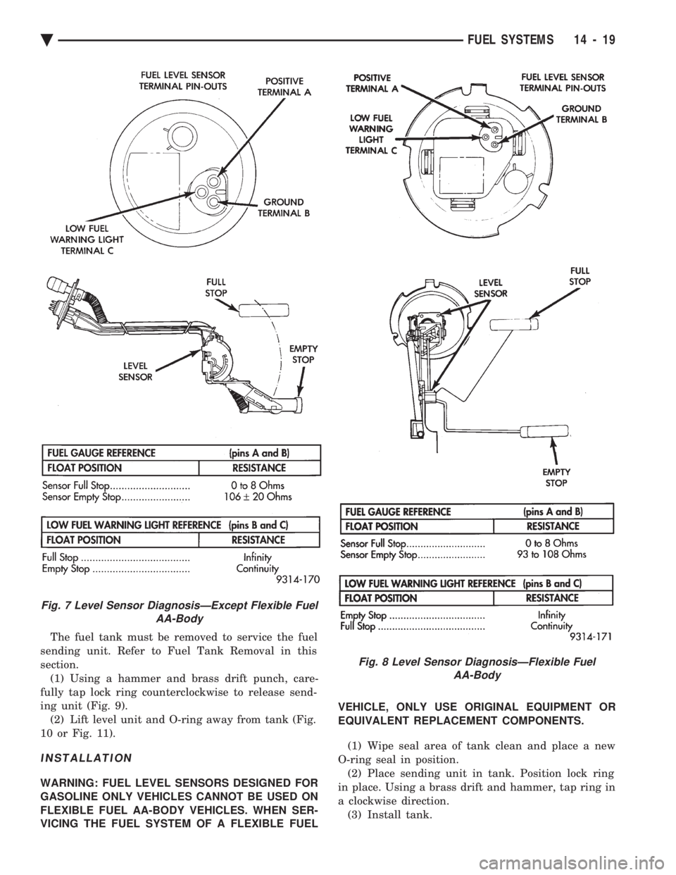
Fig. 8 Level Sensor DiagnosisÐFlexible Fuel AA-Body
Fig. 7 Level Sensor DiagnosisÐExcept Flexible Fuel AA-Body
Ä FUEL SYSTEMS 14 - 19
Page 1949 of 2438
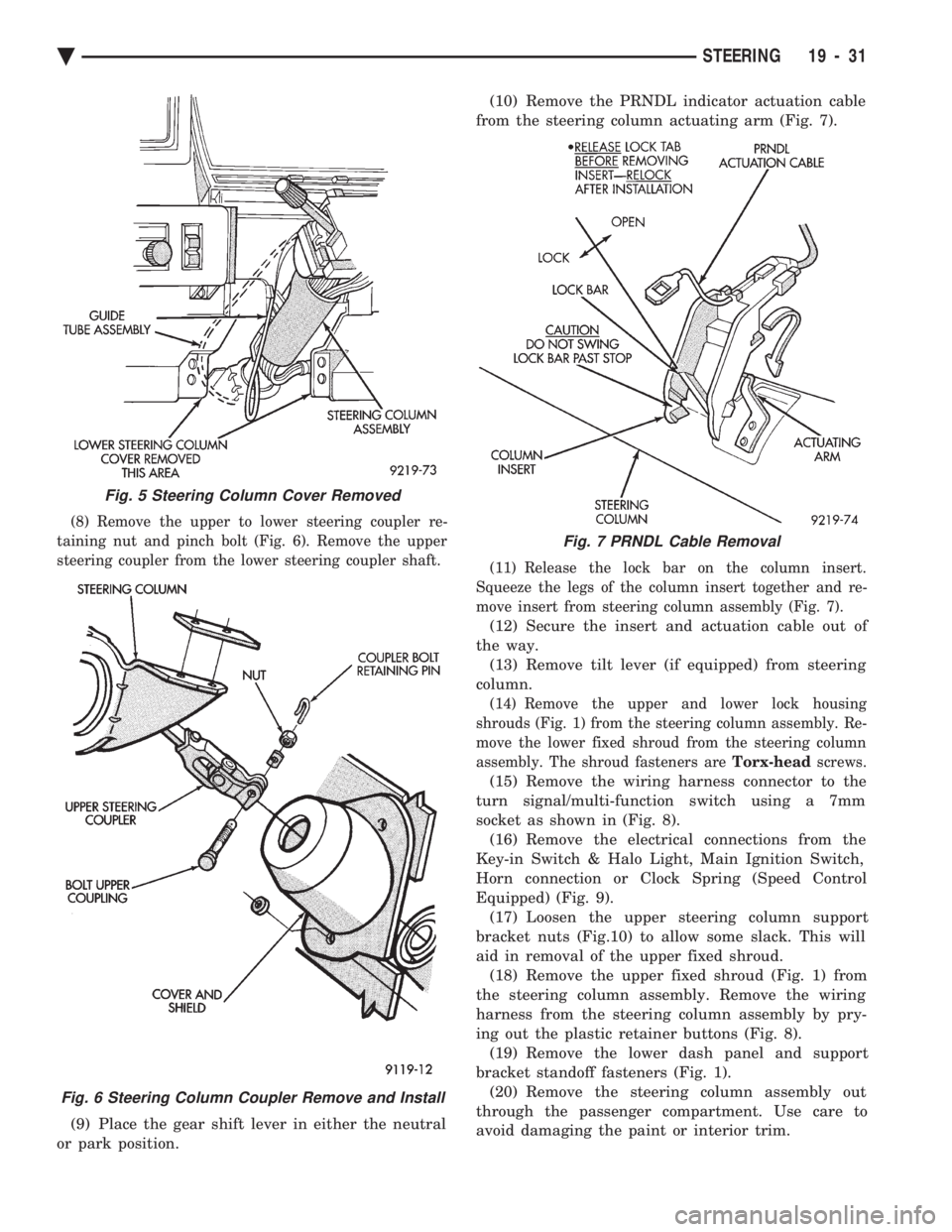
(8) Remove the upper to lower steering coupler re-
taining nut and pinch bolt (Fig. 6). Remove the upper
steering coupler from the lower steering coupler shaft.
(9) Place the gear shift lever in either the neutral
or park position. (10) Remove the PRNDL indicator actuation cable
from the steering column actuating arm (Fig. 7).
(11) Release the lock bar on the column insert.
Squeeze the legs of the column insert together and re-
move insert from steering column assembly (Fig. 7).
(12) Secure the insert and actuation cable out of
the way. (13) Remove tilt lever (if equipped) from steering
column.
(14) Remove the upper and lower lock housing
shrouds (Fig. 1) from the steering column assembly. Re-
move the lower fixed shroud from the steering column
assembly. The shroud fasteners are Torx-headscrews.
(15) Remove the wiring harness connector to the
turn signal/multi-function switch using a 7mm
socket as shown in (Fig. 8). (16) Remove the electrical connections from the
Key-in Switch & Halo Light, Main Ignition Switch,
Horn connection or Clock Spring (Speed Control
Equipped) (Fig. 9). (17) Loosen the upper steering column support
bracket nuts (Fig.10) to allow some slack. This will
aid in removal of the upper fixed shroud. (18) Remove the upper fixed shroud (Fig. 1) from
the steering column assembly. Remove the wiring
harness from the steering column assembly by pry-
ing out the plastic retainer buttons (Fig. 8). (19) Remove the lower dash panel and support
bracket standoff fasteners (Fig. 1). (20) Remove the steering column assembly out
through the passenger compartment. Use care to
avoid damaging the paint or interior trim.
Fig. 5 Steering Column Cover Removed
Fig. 6 Steering Column Coupler Remove and Install
Fig. 7 PRNDL Cable Removal
Ä STEERING 19 - 31
Page 1952 of 2438
(16) Connect the battery ground (negative) cable.
Test the operation of the lights and horns. If applica-
ble, reset the clock and radio.
STEERING COLUMN COMPONENT SERVICE
The Acustar tilt and standard steering columns
(Fig.1) have been designed to be serviced as an as-
sembly; less wiring, switches, shrouds, steering
wheel, etc. Also most steering column components
can be serviced without removing the steering col-
umn from the vehicle. For additional information on
electrical components refer to Group 8H Electrical.
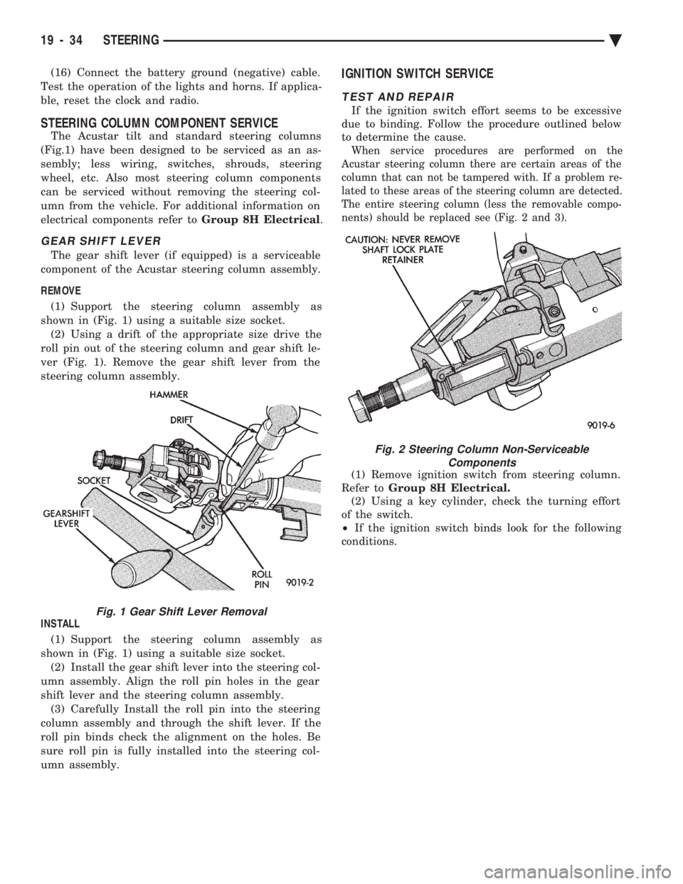
GEAR SHIFT LEVER
The gear shift lever (if equipped) is a serviceable
component of the Acustar steering column assembly.
REMOVE (1) Support the steering column assembly as
shown in (Fig. 1) using a suitable size socket. (2) Using a drift of the appropriate size drive the
roll pin out of the steering column and gear shift le-
ver (Fig. 1). Remove the gear shift lever from the
steering column assembly.
INSTALL (1) Support the steering column assembly as
shown in (Fig. 1) using a suitable size socket. (2) Install the gear shift lever into the steering col-
umn assembly. Align the roll pin holes in the gear
shift lever and the steering column assembly. (3) Carefully Install the roll pin into the steering
column assembly and through the shift lever. If the
roll pin binds check the alignment on the holes. Be
sure roll pin is fully installed into the steering col-
umn assembly.
IGNITION SWITCH SERVICE
TEST AND REPAIR
If the ignition switch effort seems to be excessive
due to binding. Follow the procedure outlined below
to determine the cause.
When service procedures are performed on the
Acustar steering column there are certain areas of the
column that can not be tampered with. If a problem re-
lated to these areas of the steering column are detected.
The entire steering column (less the removable compo-
nents) should be replaced see (Fig. 2 and 3).
(1) Remove ignition switch from steering column.
Refer to Group 8H Electrical.
(2) Using a key cylinder, check the turning effort
of the switch.
² If the ignition switch binds look for the following
conditions.
Fig. 1 Gear Shift Lever Removal
Fig. 2 Steering Column Non-Serviceable Components
19 - 34 STEERING Ä
Page 1988 of 2438
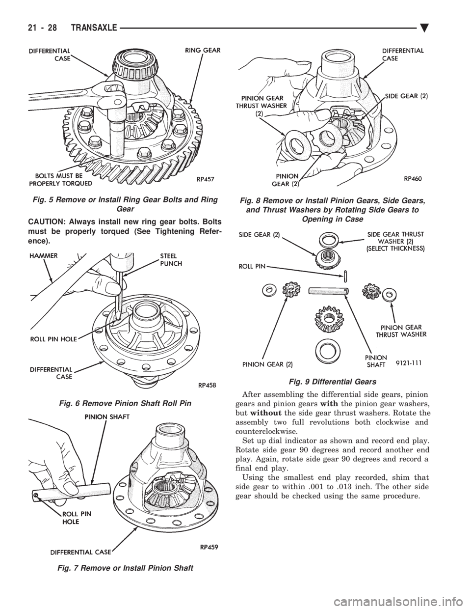
CAUTION: Always install new ring gear bolts. Bolts
must be properly torqued (See Tightening Refer-
ence). After assembling the differential side gears, pinion
gears and pinion gears withthe pinion gear washers,
but without the side gear thrust washers. Rotate the
assembly two full revolutions both clockwise and
counterclockwise. Set up dial indicator as shown and record end play.
Rotate side gear 90 degrees and record another end
play. Again, rotate side gear 90 degrees and record a
final end play. Using the smallest end play recorded, shim that
side gear to within .001 to .013 inch. The other side
gear should be checked using the same procedure.
Fig. 5 Remove or Install Ring Gear Bolts and Ring Gear
Fig. 6 Remove Pinion Shaft Roll Pin
Fig. 7 Remove or Install Pinion Shaft
Fig. 8 Remove or Install Pinion Gears, Side Gears,and Thrust Washers by Rotating Side Gears to Opening in Case
Fig. 9 Differential Gears
21 - 28 TRANSAXLE Ä
Page 1991 of 2438
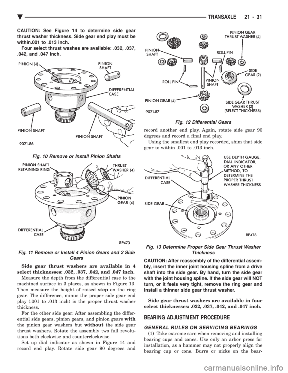
CAUTION: See Figure 14 to determine side gear
thrust washer thickness. Side gear end play must be
within.001 to .013 inch.Four select thrust washes are available: .032, .037,
.042, and .047 inch.
Side gear thrust washers are available in 4
select thicknesses: .032, .037, .042, and .047 inch. Measure the depth from the differential case to the
machined surface in 3 places, as shown in Figure 13.
Then measure the height of raised stepon the ring
gear. The difference, minus the proper side gear end
play (.001 to .013 inch) is the proper thrust washer
thickness. For the other side gear: After assembling the differ-
ential side gears, pinion gears, and pinion gears with
the pinion gear washers but withoutthe side gear
thrust washers. Rotate the assembly two full revolu-
tions both clockwise and counterclockwise. Set up dial indicator as shown in Figure 14 and
record end play. Rotate side gear 90 degrees and record another end play. Again, rotate side gear 90
degrees and record a final end play.
Using the smallest end play recorded, shim that side
gear to within .001 to .013 inch.
CAUTION: After reassembly of the differential assem-
bly, insert the inner joint housing spline from a drive
shaft into the side gear. By hand, turn the side gear
with the joint housing spline. If the side gear will NOT
turn, or it feels very tight, remove the ring gear and
install a thinner side gear thrust washer.
Side gear thrust washers are available in four
select thicknesses: .032, .037, .042, and .047 inch.
BEARING ADJUSTMENT PROCEDURE
GENERAL RULES ON SERVICING BEARINGS
(1) Take extreme care when removing and installing
bearing cups and cones. Use only an arbor press for
installation, as a hammer may not properly align the
bearing cup or cone. Burrs or nicks on the bear-
Fig. 12 Differential Gears
Fig. 13 Determine Proper Side Gear Thrust Washer Thickness
Fig. 10 Remove or Install Pinion Shafts
Fig. 11 Remove or Install 4 Pinion Gears and 2 Side Gears
Ä TRANSAXLE 21 - 31