1993 CHEVROLET PLYMOUTH ACCLAIM Wire diagram 89
[x] Cancel search: Wire diagram 89Page 756 of 2438

(5) Reset the terminal locking tang, if it has one.
(6) Insert the removed wire in the same cavity on
the repair connector. (7) Repeat steps four thru six for each wire in the
connector. Check that all wires are inserted into the
proper cavities. For connector pin out identification
refer to the wiring diagrams. (8) Insert the connector locking wedge into the re-
paired connector. (9) Connect connector to its mating half.
(10) Connect battery and test all affected systems.
CONNECTOR AND TERMINAL ASSEMBLY REPLACEMENT
(1) Disconnect Battery.
(2) Disconnect the connector being repaired form
its mating half. (3) Cut off the existing wire connector directly be-
hind the insulator. Remove six inches of tape from
the harness. (4) Stagger cut all wires on the harness side about
1/2 inch apart (Fig. 14). (5) Remove 1 inch of insulation from each wire on
the harness side. (6) Stagger cut the matching wires on the repair
connector assembly in the opposite order as was done
on the harness side of the repair. Allow extra length
for soldered connections. Check that the overall
length is the same as the original (Fig. 14). (7) Remove 1 inch of insulation from each wire.
(8) Place a piece of heat shrink tubing over one
side of the wire. Make sure the tubing will be long
enough to cover and seal the entire repair area. (9) Spread the strands of the wire apart on each
part of the exposed wires (Fig. 11 example 1). (10) Push the two ends of wire together until the
strands of wire are close to the insulation (Fig. 11 ex-
ample 2). (11) Twist the wires together (Fig. 11 example 3). (12) Solder the connection together using rosin
core type solder only. Do not use acid core solder.
(13) Center the heat shrink tubing over the joint
and heat using a heat gun. Heat the joint until the
tubing is tightly sealed and sealant comes out of both
ends of the tubing. (14) Repeat steps 8 thru 13 for each wire.
(15) Re-tape the wire harness starting 1-1/2 inches
behind the connector and 2 inches past the repair. (16) Reconnect the repaired connector.
(17) Connect battery and test all affected systems.
TERMINAL REPLACEMENT
(1) Disconnect battery.
(2) Disconnect the connector being repaired form
its mating half. (3) Remove connector locking wedge (Fig. 12).
(4) Position the connector locking finger away from
the terminal. Pull on the wire to remove the termi-
nal from the connector (Fig. 13). (5) Cut the wire 6 inches from the back of the con-
nector. (6) Remove 1 inch of insulation from the wire on
the harness side. (7) Select a wire from the terminal repair assem-
bly that best matches the color wire being repaired. (8) Cut the repair wire to the proper length and re-
move 1 inch of insulation. (9) Place a piece of heat shrink tubing over one
side of the wire. Make sure the tubing will be long
enough to cover and seal the entire repair area. (10) Spread the strands of the wire apart on each
part of the exposed wires (Fig. 11 example 1). (11) Push the two ends of wire together until the
strands of wire are close to the insulation (Fig. 11 ex-
ample 2). (12) Twist the wires together (Fig. 11 example 3).
(13) Solder the connection together using rosin
core type solder only. Do not use acid core solder.
Fig. 13 Connector Locking Finger and Locking
Wedge
Fig. 14 Stagger Cutting Wires
8W - 6 GENERAL INFORMATION Ä
Page 757 of 2438

(14) Center the heat shrink tubing over the joint
and heat using a heat gun. Heat the joint until the
tubing is tightly sealed and sealant comes out of both
ends of the tubing. (15) Insert the repaired wire into the connector.
(16) Install the connector locking wedge and recon-
nect the connector to its mating half. (17) Re-tape the wire harness starting 1-1/2 inches
behind the connector and 2 inches past the repair. (18) Connect battery and test all affected systems.
SYMBOLS, FUSES AND RELAYS
Various symbols are used throughout the wiring
diagrams. These symbols can be identified by refer-
ring to the symbol identification chart (Fig. 15). For fuse block, relay bank, or power distribution
center information refer to the fuse charts and relay
bank section.
CAUTION: When replacing a blown fuse it is impor-
tant to replace it with a fuse having the correct am-
perage rating. The use of a fuse with a rating other
than indicated may result in an electrical overload.
If a proper rated fuse continues to blow, it indicates
a problem that should be corrected.
Ä GENERAL INFORMATION 8W - 7
Page 1775 of 2438
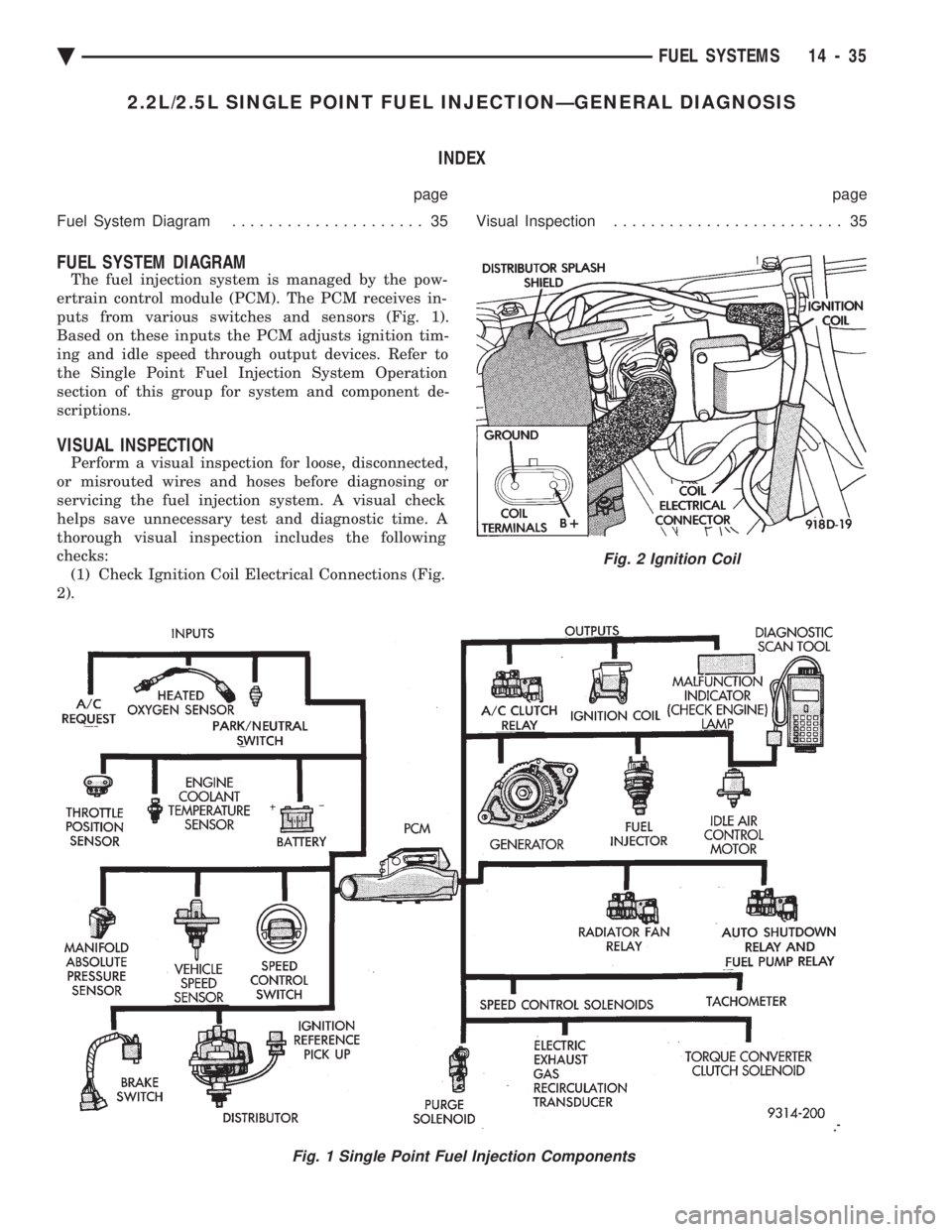
2.2L/2.5L SINGLE POINT FUEL INJECTIONÐGENERAL DIAGNOSIS INDEX
page page
Fuel System Diagram ..................... 35 Visual Inspection......................... 35
FUEL SYSTEM DIAGRAM
The fuel injection system is managed by the pow-
ertrain control module (PCM). The PCM receives in-
puts from various switches and sensors (Fig. 1).
Based on these inputs the PCM adjusts ignition tim-
ing and idle speed through output devices. Refer to
the Single Point Fuel Injection System Operation
section of this group for system and component de-
scriptions.
VISUAL INSPECTION
Perform a visual inspection for loose, disconnected,
or misrouted wires and hoses before diagnosing or
servicing the fuel injection system. A visual check
helps save unnecessary test and diagnostic time. A
thorough visual inspection includes the following
checks: (1) Check Ignition Coil Electrical Connections (Fig.
2).
Fig. 1 Single Point Fuel Injection Components
Fig. 2 Ignition Coil
Ä FUEL SYSTEMS 14 - 35
Page 1806 of 2438
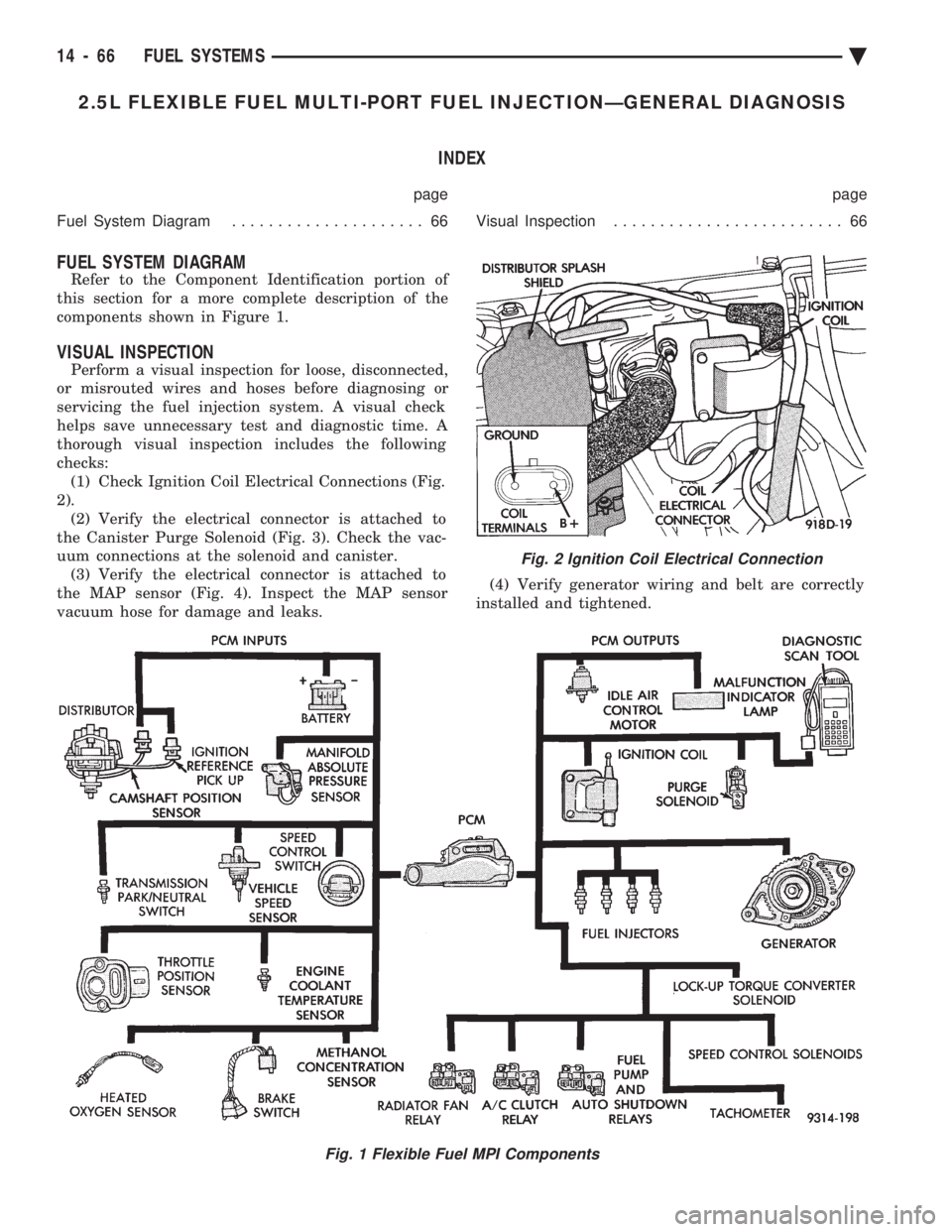
2.5L FLEXIBLE FUEL MULTI-PORT FUEL INJECTIONÐGENERAL DIAGNOSIS INDEX
page page
Fuel System Diagram ..................... 66 Visual Inspection......................... 66
FUEL SYSTEM DIAGRAM
Refer to the Component Identification portion of
this section for a more complete description of the
components shown in Figure 1.
VISUAL INSPECTION
Perform a visual inspection for loose, disconnected,
or misrouted wires and hoses before diagnosing or
servicing the fuel injection system. A visual check
helps save unnecessary test and diagnostic time. A
thorough visual inspection includes the following
checks: (1) Check Ignition Coil Electrical Connections (Fig.
2). (2) Verify the electrical connector is attached to
the Canister Purge Solenoid (Fig. 3). Check the vac-
uum connections at the solenoid and canister. (3) Verify the electrical connector is attached to
the MAP sensor (Fig. 4). Inspect the MAP sensor
vacuum hose for damage and leaks. (4) Verify generator wiring and belt are correctly
installed and tightened.
Fig. 1 Flexible Fuel MPI Components
Fig. 2 Ignition Coil Electrical Connection
14 - 66 FUEL SYSTEMS Ä
Page 1835 of 2438
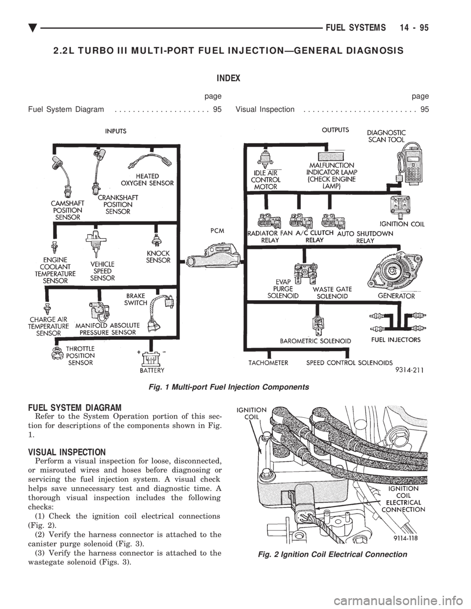
2.2L TURBO III MULTI-PORT FUEL INJECTIONÐGENERAL DIAGNOSIS INDEX
page page
Fuel System Diagram ..................... 95 Visual Inspection......................... 95
FUEL SYSTEM DIAGRAM
Refer to the System Operation portion of this sec-
tion for descriptions of the components shown in Fig.
1.
VISUAL INSPECTION
Perform a visual inspection for loose, disconnected,
or misrouted wires and hoses before diagnosing or
servicing the fuel injection system. A visual check
helps save unnecessary test and diagnostic time. A
thorough visual inspection includes the following
checks: (1) Check the ignition coil electrical connections
(Fig. 2). (2) Verify the harness connector is attached to the
canister purge solenoid (Fig. 3). (3) Verify the harness connector is attached to the
wastegate solenoid (Figs. 3).
Fig. 1 Multi-port Fuel Injection Components
Fig. 2 Ignition Coil Electrical Connection
Ä FUEL SYSTEMS 14 - 95
Page 1845 of 2438
Wastegate Duty Cycle
Battery Temperature
Map Sensor Voltage
Vehicle Speed
Oxygen Sensor State
Baro Read Update
MAP Gauge Reading
Throttle Opening (percentage)
Total Spark Advance
CIRCUIT ACTUATION TEST MODE
The purpose of the circuit actuation test mode is to
check for the proper operation of output circuits or
devices which the powertrain control module (PCM)
cannot internally recognize. The PCM can attempt to
activate these outputs and allow an observer to ver-
ify proper operation. Most of the tests available in
this mode provide an audible or visual indication of
device operation (click of relay contacts, spray fuel,
etc.). With the exception of an intermittent condition,
if a device functions properly during its test, assume
the device, its associated wiring, and its driver cir-
cuit are in working order.
OBTAINING CIRCUIT ACTUATION TEST
Connect the DRBII scan tool to the vehicle and ac-
cess the Actuators screen. The following is a list of
the engine control system functions accessible
through Actuators screens. Stop All Tests
Ignition Coil #1
Ignition Coil #2
Fuel Injector #1
Fuel Injector #2
Fuel Injector #3
Idle Air Control Motor Open/Close
Radiator Fan Relay
A/C Clutch Relay
Auto Shutdown Relay
Purge Solenoid
S/C Serv Solenoids
Generator Field
Tachometer Output
Wastegate Solenoid
Baro Read Solenoid
All Solenoids/Relays
Speed Control Vent Solenoid
Speed Control Vacuum Solenoid
ASD Fuel System Test
Fuel Injector #4
THROTTLE BODY MINIMUM AIR FLOW CHECK
PROCEDURE
(1) Warm the engine in neutral until the cooling
fan has cycled on and off at least once. (2) Shut off engine.
(3) Hook-up Tachometer.
(4) Disconnect the PCV valve hose from the nipple
on the intake manifold. (5) Attach air metering fitting, special tool 6457
(0.125 inch orifice), to the intake manifold PCV nip-
ple. (6) Disconnect 3/16 inch manifold vacuum purge
line from the top of the throttle body. Cap the 3/16
inch throttle body nipple. (7) Connect DRBII scan tool.
(8) Restart engine. Allow engine to idle for at least
one minute. (9) Using the DRBII scan tool, access Min. Airflow
Idle Spd. The following will then occur:
² Idle air control motor will fully close.
² Idle spark advance will become fixed.
² Engine RPM will be displayed on the DRBII scan
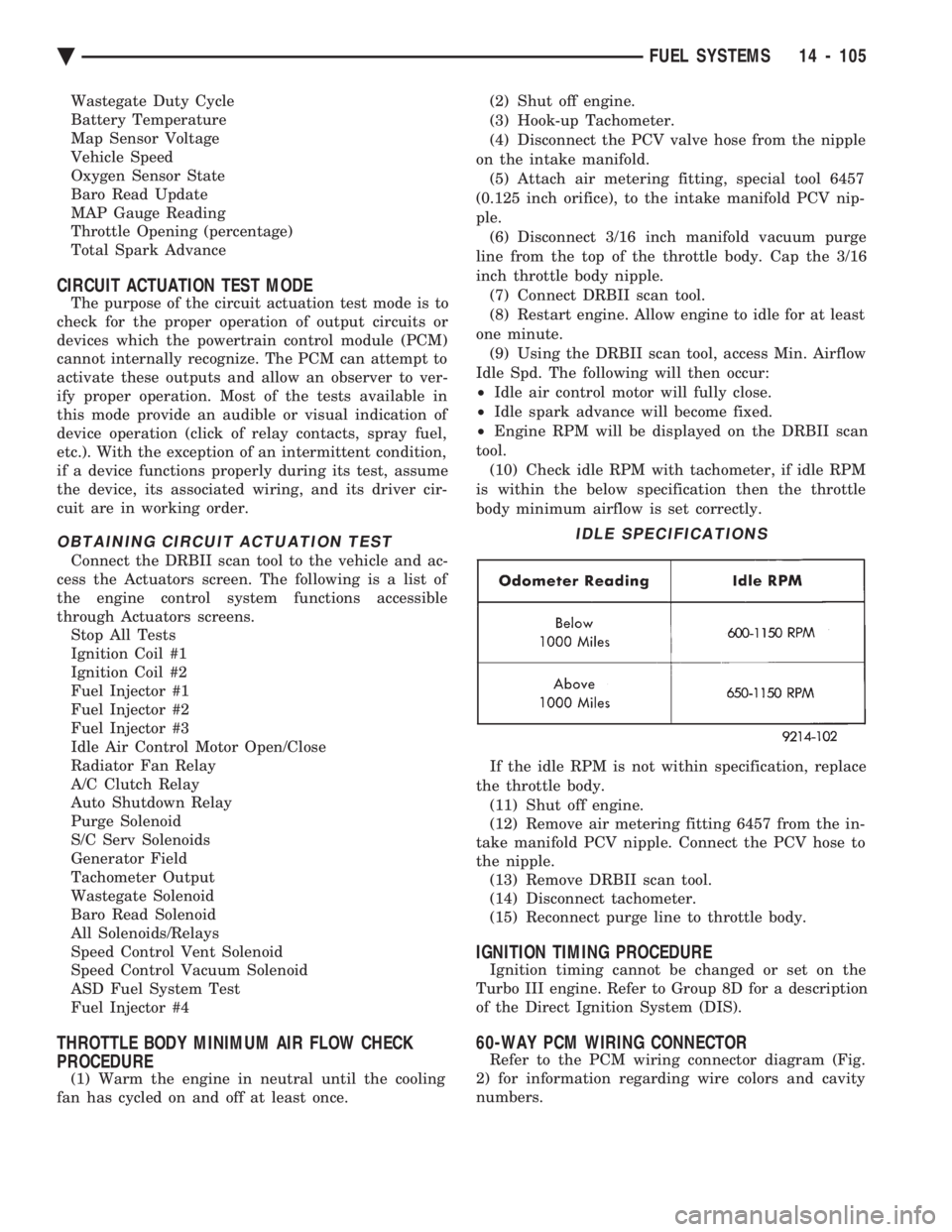
tool. (10) Check idle RPM with tachometer, if idle RPM
is within the below specification then the throttle
body minimum airflow is set correctly.
If the idle RPM is not within specification, replace
the throttle body. (11) Shut off engine.
(12) Remove air metering fitting 6457 from the in-
take manifold PCV nipple. Connect the PCV hose to
the nipple. (13) Remove DRBII scan tool.
(14) Disconnect tachometer.
(15) Reconnect purge line to throttle body.
IGNITION TIMING PROCEDURE
Ignition timing cannot be changed or set on the
Turbo III engine. Refer to Group 8D for a description
of the Direct Ignition System (DIS).
60-WAY PCM WIRING CONNECTOR
Refer to the PCM wiring connector diagram (Fig.
2) for information regarding wire colors and cavity
numbers.
IDLE SPECIFICATIONS
Ä FUEL SYSTEMS 14 - 105
Page 1865 of 2438
3.0L MULTI-PORT FUEL INJECTIONÐGENERAL DIAGNOSIS INDEX
page page
Fuel System Diagram .................... 125 Visual Inspection........................ 125
FUEL SYSTEM DIAGRAM
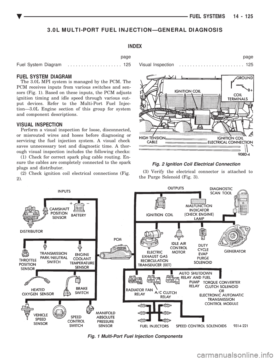
The 3.0L MPI system is managed by the PCM. The
PCM receives inputs from various switches and sen-
sors (Fig. 1). Based on these inputs, the PCM adjusts
ignition timing and idle speed through various out-
put devices. Refer to the Multi-Port Fuel Injec-
tionÐ3.0L Engine section of this group for system
and component descriptions.
VISUAL INSPECTION
Perform a visual inspection for loose, disconnected,
or misrouted wires and hoses before diagnosing or
servicing the fuel injection system. A visual check
saves unnecessary test and diagnostic time. A thor-
ough visual inspection includes the following checks: (1) Check for correct spark plug cable routing. En-
sure the cables are completely connected to the spark
plugs and distributor. (2) Check ignition coil electrical connections (Fig.
2). (3) Verify the electrical connector is attached to
the Purge Solenoid (Fig. 3).
Fig. 1 Multi-Port Fuel Injection Components
Fig. 2 Ignition Coil Electrical Connection
Ä FUEL SYSTEMS 14 - 125
Page 1878 of 2438
3.0L MULTI-PORT FUEL INJECTIONÐSERVICE PROCEDURES INDEX
page page
Idle Air Control Motor .................... 138
Canister Purge Solenoid Service ............ 143
Fuel Injector Rail Assembly ................ 139
Fuel Injectors .......................... 142
Fuel Pressure Regulator Service ............ 141
Fuel System Pressure Release Procedure ..... 138 Heated Oxygen Sensor (O
2Sensor)
......... 144
Manifold Absolute Pressure (MAP) Sensor ..... 143
PCM ................................. 143
Throttle Body ........................... 138
Throttle Body Service .................... 138
Throttle Position Sensor .................. 138
THROTTLE BODY SERVICE
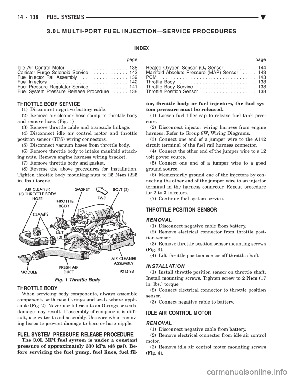
(1) Disconnect negative battery cable.
(2) Remove air cleaner hose clamp to throttle body
and remove hose. (Fig. 1) (3) Remove throttle cable and transaxle linkage.
(4) Disconnect idle air control motor and throttle
position sensor (TPS) wiring connectors. (5) Disconnect vacuum hoses from throttle body.
(6) Remove throttle body to intake manifold attach-
ing nuts. Remove engine harness wiring bracket. (7) Remove throttle body and gasket.
(8) Reverse the above procedures for installation.
Tighten throttle body mounting nuts to 25 N Im (225
in. lbs.) torque.
THROTTLE BODY
When servicing body components, always assemble
components with new O-rings and seals where appli-
cable (Fig. 2). Never use lubricants on O-rings or seals,
damage may result. If assembly of component is diffi-
cult, use water to aid assembly. Use care when remov-
ing hoses to prevent damage to hose or hose nipple.
FUEL SYSTEM PRESSURE RELEASE PROCEDURE
The 3.0L MPI fuel system is under a constant
pressure of approximately 330 kPa (48 psi). Be-
fore servicing the fuel pump, fuel lines, fuel fil- ter, throttle body or fuel injectors, the fuel sys-
tem pressure must be released. (1) Loosen fuel filler cap to release fuel tank pres-
sure. (2) Disconnect injector wiring harness from engine
harness. Refer to Group 8W, Wiring Diagrams. (3) Connect one end of a jumper wire to the A142
circuit terminal of the fuel rail harness connector. (4) Connect the other end of the jumper wire to a 12
volt power source. (5) Connect one end of a jumper wire to a good
ground source. (6) Momentarily ground one of the injectors by con-
necting the other end of the jumper wire to an injector
terminal in the harness connector. Repeat procedure
for 2 to 3 injectors. (7) Continue fuel system service.
THROTTLE POSITION SENSOR
REMOVAL
(1) Disconnect negative cable from battery.
(2) Remove electrical connector from throttle posi-
tion sensor. (3) Remove throttle position sensor mounting screws
(Fig. 3). (4) Lift throttle position sensor off throttle shaft.
INSTALLATION
(1) Install throttle position sensor on throttle shaft.
Install mounting screws. Tighten screw to 2 N Im (17
in. lbs.) torque. (2) Connect electrical connector to throttle position
sensor. (3) Connect negative cable to battery.
IDLE AIR CONTROL MOTOR
REMOVAL
(1) Disconnect negative cable from battery.
(2) Remove electrical connector from idle air control
motor. (3) Remove idle air control motor mounting screws
(Fig. 4).
Fig. 1 Throttle Body
14 - 138 FUEL SYSTEMS Ä