1993 CHEVROLET PLYMOUTH ACCLAIM ignition
[x] Cancel search: ignitionPage 1958 of 2438
INSTALL
CAUTION: When installing interlock cable assem-
bly, care must be taken not to bend exposed cable
wire and slug at shifter end of cable.
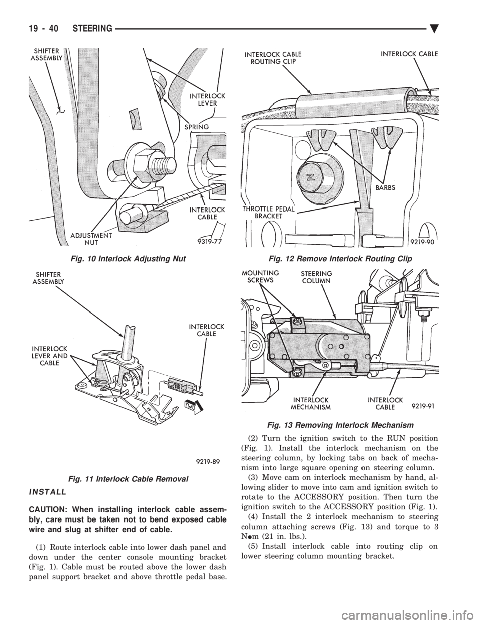
(1) Route interlock cable into lower dash panel and
down under the center console mounting bracket
(Fig. 1). Cable must be routed above the lower dash
panel support bracket and above throttle pedal base. (2) Turn the ignition switch to the RUN position
(Fig. 1). Install the interlock mechanism on the
steering column, by locking tabs on back of mecha-
nism into large square opening on steering column. (3) Move cam on interlock mechanism by hand, al-
lowing slider to move into cam and ignition switch to
rotate to the ACCESSORY position. Then turn the
ignition switch to the ACCESSORY position (Fig. 1). (4) Install the 2 interlock mechanism to steering
column attaching screws (Fig. 13) and torque to 3
N Im (21 in. lbs.).
(5) Install interlock cable into routing clip on
lower steering column mounting bracket.
Fig. 10 Interlock Adjusting Nut
Fig. 11 Interlock Cable Removal
Fig. 12 Remove Interlock Routing Clip
Fig. 13 Removing Interlock Mechanism
19 - 40 STEERING Ä
Page 1959 of 2438
CAUTION: Interlock cable must by completely
clipped to the throttle pedal bracket with both barbs
of clip fully installed through mounting holes. This
is to prevent interference with throttle pedal.
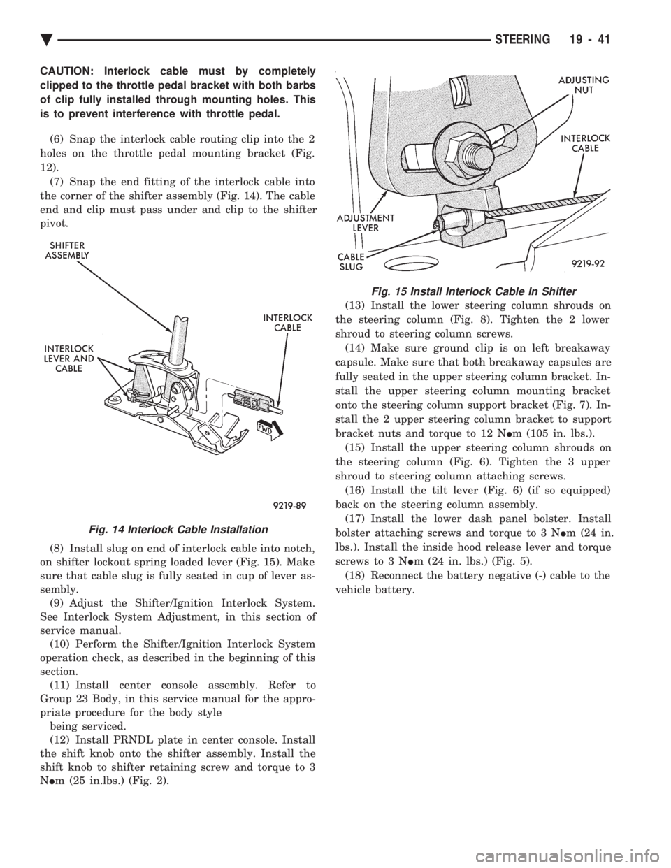
(6) Snap the interlock cable routing clip into the 2
holes on the throttle pedal mounting bracket (Fig.
12). (7) Snap the end fitting of the interlock cable into
the corner of the shifter assembly (Fig. 14). The cable
end and clip must pass under and clip to the shifter
pivot.
(8) Install slug on end of interlock cable into notch,
on shifter lockout spring loaded lever (Fig. 15). Make
sure that cable slug is fully seated in cup of lever as-
sembly. (9) Adjust the Shifter/Ignition Interlock System.
See Interlock System Adjustment, in this section of
service manual. (10) Perform the Shifter/Ignition Interlock System
operation check, as described in the beginning of this
section. (11) Install center console assembly. Refer to
Group 23 Body, in this service manual for the appro-
priate procedure for the body style being serviced.
(12) Install PRNDL plate in center console. Install
the shift knob onto the shifter assembly. Install the
shift knob to shifter retaining screw and torque to 3
N Im (25 in.lbs.) (Fig. 2). (13) Install the lower steering column shrouds on
the steering column (Fig. 8). Tighten the 2 lower
shroud to steering column screws. (14) Make sure ground clip is on left breakaway
capsule. Make sure that both breakaway capsules are
fully seated in the upper steering column bracket. In-
stall the upper steering column mounting bracket
onto the steering column support bracket (Fig. 7). In-
stall the 2 upper steering column bracket to support
bracket nuts and torque to 12 N Im (105 in. lbs.).
(15) Install the upper steering column shrouds on
the steering column (Fig. 6). Tighten the 3 upper
shroud to steering column attaching screws. (16) Install the tilt lever (Fig. 6) (if so equipped)
back on the steering column assembly. (17) Install the lower dash panel bolster. Install
bolster attaching screws and torque to 3 N Im (24 in.
lbs.). Install the inside hood release lever and torque
screws to 3 N Im (24 in. lbs.) (Fig. 5).
(18) Reconnect the battery negative (-) cable to the
vehicle battery.
Fig. 14 Interlock Cable Installation
Fig. 15 Install Interlock Cable In Shifter
Ä STEERING 19 - 41
Page 2060 of 2438
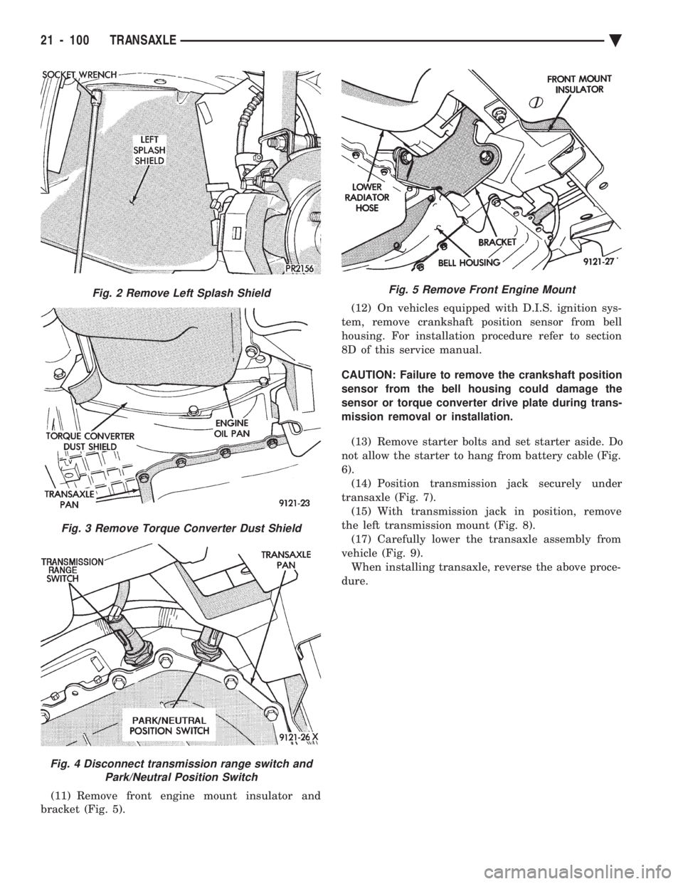
(11) Remove front engine mount insulator and
bracket (Fig. 5). (12) On vehicles equipped with D.I.S. ignition sys-
tem, remove crankshaft position sensor from bell
housing. For installation procedure refer to section
8D of this service manual.
CAUTION: Failure to remove the crankshaft position
sensor from the bell housing could damage the
sensor or torque converter drive plate during trans-
mission removal or installation.
(13) Remove starter bolts and set starter aside. Do
not allow the starter to hang from battery cable (Fig.
6). (14) Position transmission jack securely under
transaxle (Fig. 7). (15) With transmission jack in position, remove
the left transmission mount (Fig. 8). (17) Carefully lower the transaxle assembly from
vehicle (Fig. 9). When installing transaxle, reverse the above proce-
dure.
Fig. 2 Remove Left Splash Shield
Fig. 3 Remove Torque Converter Dust Shield
Fig. 4 Disconnect transmission range switch and Park/Neutral Position Switch
Fig. 5 Remove Front Engine Mount
21 - 100 TRANSAXLE Ä
Page 2352 of 2438
WARNING: AVOID RADIATOR/CONDENSER FAN
BLADES WHEN WORKING IN THE RADIATOR
AREA. FAN IS CONTROLLED BY TEMPERATURE
AND CAN START ANY TIME IGNITION IS ON. PER-
SONAL INJURY CAN RESULT.
(1) Disconnect fan control switch wire connector.
(2) Using a suitable jumper wire, jump across ter-
minals in wire connector. (3) Connect a suitable continuity tester across fan
control switch terminals. (4) Start engine and set idle at 1300 rpm. The ra-
diator fan should run constantly. (5) Set the A/C controls to A/C and high blower.
(6) If the high pressure gauge reads below 1102
kPa (160 psi) there should be no continuity across
the switch terminals.
CAUTION: Do not allow engine to overheat when ra-
diator air flow is blocked.
(7) Block radiator air flow with a suitable cover to
increase the high side pressure to at least 1585 kPa
(230 psi). Electrical continuity should be detected
across the fan control switch terminals. (8) Remove cover from front of vehicle to allow
high side pressure to decrease. When pressure drops
below 1102 kPa (160 psi), continuity should cease. If fan control switch is defective, replace it.
REMOVAL AND INSTALLATION
CAUTION: Refrigerant removal is not necessary
when removing the Condenser Fan Control Switch.
However, a small amount of refrigerant will vent
from the switch port. Review the refrigerant han-
dling section of Safety Precautions and Warnings in
the General Information section of this Group.
(1) Disconnect wire connector from condenser fan
control switch. (2) Loosen and quickly rotate the switch counter-
clockwise and separate from the high pressure line
switch port. To install, reverse the preceding operation.
DIFFERENTIAL PRESSURE CUT-OUT SWITCH
DIAGNOSIS
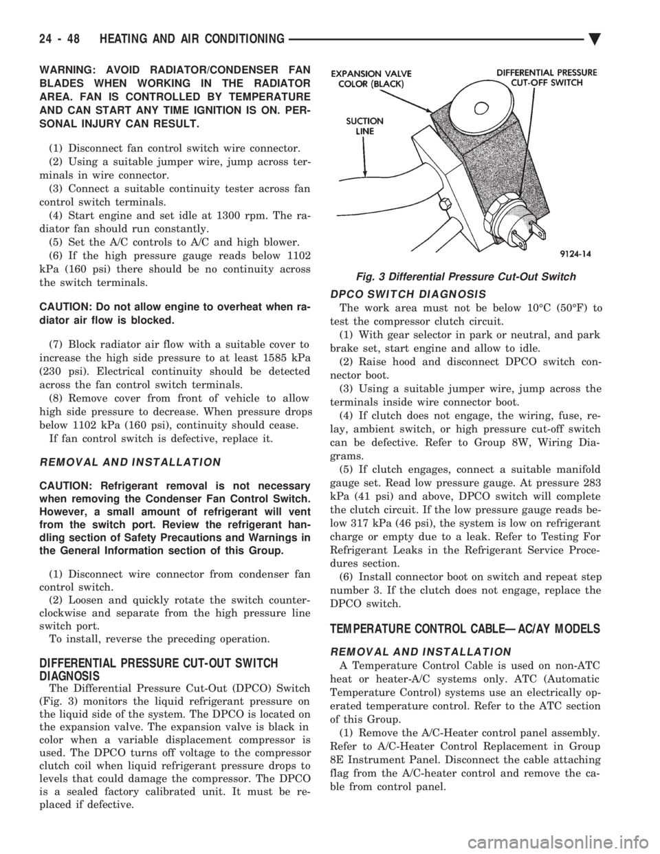
The Differential Pressure Cut-Out (DPCO) Switch
(Fig. 3) monitors the liquid refrigerant pressure on
the liquid side of the system. The DPCO is located on
the expansion valve. The expansion valve is black in
color when a variable displacement compressor is
used. The DPCO turns off voltage to the compressor
clutch coil when liquid refrigerant pressure drops to
levels that could damage the compressor. The DPCO
is a sealed factory calibrated unit. It must be re-
placed if defective.
DPCO SWITCH DIAGNOSIS
The work area must not be below 10ÉC (50ÉF) to
test the compressor clutch circuit. (1) With gear selector in park or neutral, and park
brake set, start engine and allow to idle. (2) Raise hood and disconnect DPCO switch con-
nector boot. (3) Using a suitable jumper wire, jump across the
terminals inside wire connector boot. (4) If clutch does not engage, the wiring, fuse, re-
lay, ambient switch, or high pressure cut-off switch
can be defective. Refer to Group 8W, Wiring Dia-
grams. (5) If clutch engages, connect a suitable manifold
gauge set. Read low pressure gauge. At pressure 283
kPa (41 psi) and above, DPCO switch will complete
the clutch circuit. If the low pressure gauge reads be-
low 317 kPa (46 psi), the system is low on refrigerant
charge or empty due to a leak. Refer to Testing For
Refrigerant Leaks in the Refrigerant Service Proce-
dures section. (6) Install connector boot on switch and repeat step
number 3. If the clutch does not engage, replace the
DPCO switch.
TEMPERATURE CONTROL CABLEÐAC/AY MODELS
REMOVAL AND INSTALLATION
A Temperature Control Cable is used on non-ATC
heat or heater-A/C systems only. ATC (Automatic
Temperature Control) systems use an electrically op-
erated temperature control. Refer to the ATC section
of this Group. (1) Remove the A/C-Heater control panel assembly.
Refer to A/C-Heater Control Replacement in Group
8E Instrument Panel. Disconnect the cable attaching
flag from the A/C-heater control and remove the ca-
ble from control panel.
Fig. 3 Differential Pressure Cut-Out Switch
24 - 48 HEATING AND AIR CONDITIONING Ä
Page 2372 of 2438
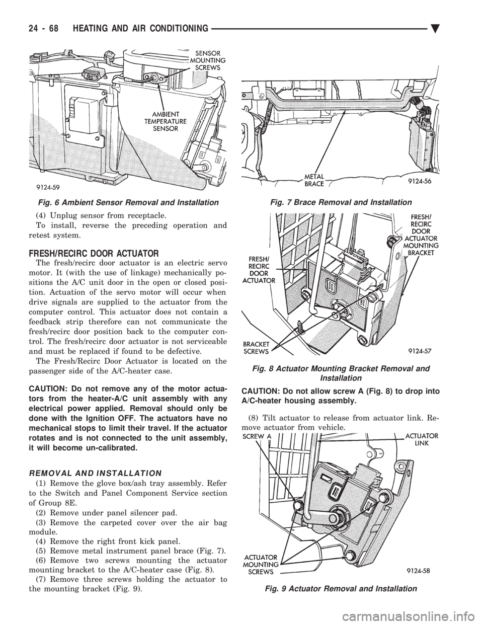
(4) Unplug sensor from receptacle.
To install, reverse the preceding operation and
retest system.
FRESH/RECIRC DOOR ACTUATOR
The fresh/recirc door actuator is an electric servo
motor. It (with the use of linkage) mechanically po-
sitions the A/C unit door in the open or closed posi-
tion. Actuation of the servo motor will occur when
drive signals are supplied to the actuator from the
computer control. This actuator does not contain a
feedback strip therefore can not communicate the
fresh/recirc door position back to the computer con-
trol. The fresh/recirc door actuator is not serviceable
and must be replaced if found to be defective. The Fresh/Recirc Door Actuator is located on the
passenger side of the A/C-heater case.
CAUTION: Do not remove any of the motor actua-
tors from the heater-A/C unit assembly with any
electrical power applied. Removal should only be
done with the Ignition OFF. The actuators have no
mechanical stops to limit their travel. If the actuator
rotates and is not connected to the unit assembly,
it will become un-calibrated.
REMOVAL AND INSTALLATION
(1) Remove the glove box/ash tray assembly. Refer
to the Switch and Panel Component Service section
of Group 8E. (2) Remove under panel silencer pad.
(3) Remove the carpeted cover over the air bag
module. (4) Remove the right front kick panel.
(5) Remove metal instrument panel brace (Fig. 7).
(6) Remove two screws mounting the actuator
mounting bracket to the A/C-heater case (Fig. 8). (7) Remove three screws holding the actuator to
the mounting bracket (Fig. 9). CAUTION: Do not allow screw A (Fig. 8) to drop into
A/C-heater housing assembly.
(8) Tilt actuator to release from actuator link. Re-
move actuator from vehicle.
Fig. 9 Actuator Removal and Installation
Fig. 6 Ambient Sensor Removal and InstallationFig. 7 Brace Removal and Installation
Fig. 8 Actuator Mounting Bracket Removal and Installation
24 - 68 HEATING AND AIR CONDITIONING Ä
Page 2373 of 2438
To install, reverse the preceding operation.
BLEND-AIR DOOR ACTUATOR
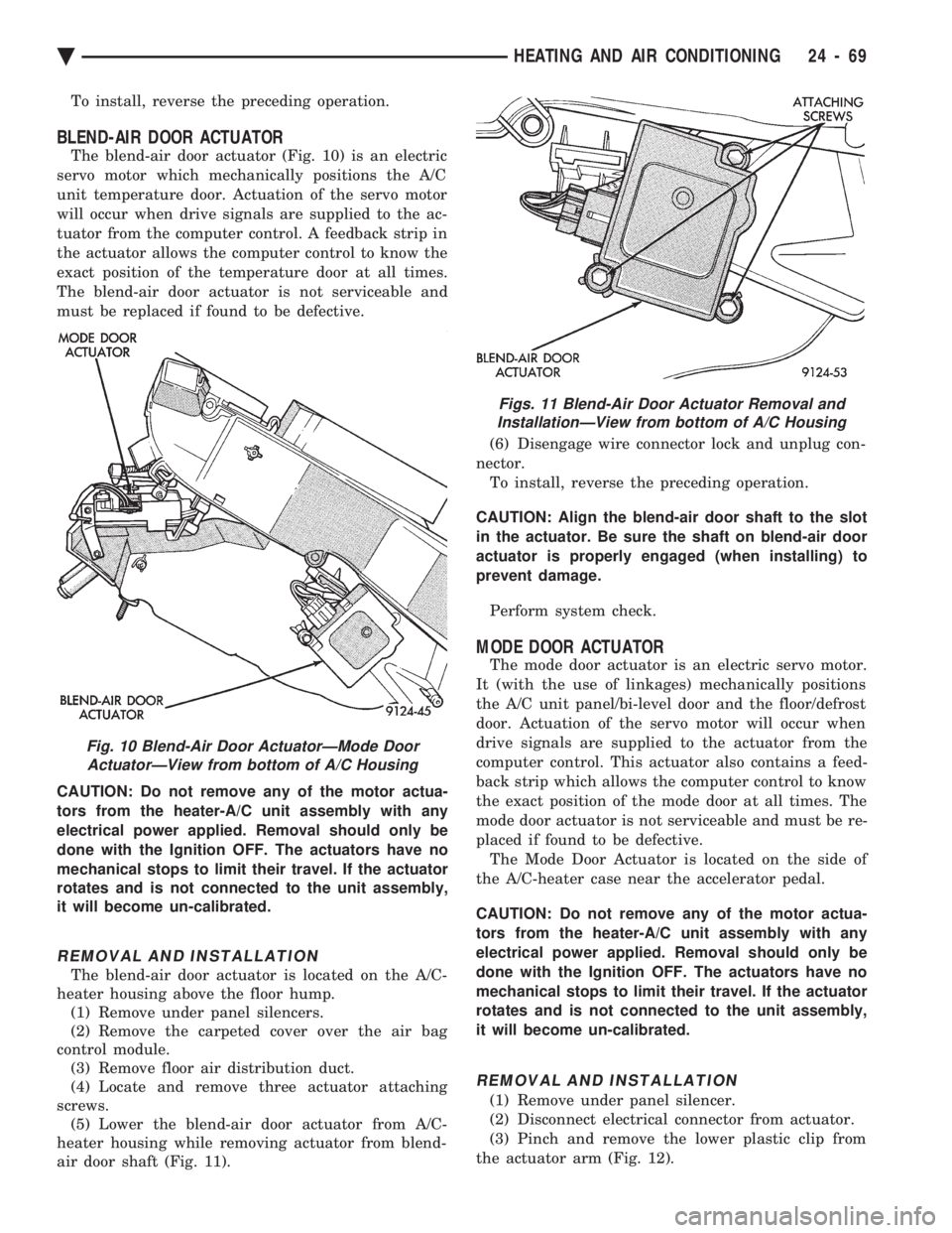
The blend-air door actuator (Fig. 10) is an electric
servo motor which mechanically positions the A/C
unit temperature door. Actuation of the servo motor
will occur when drive signals are supplied to the ac-
tuator from the computer control. A feedback strip in
the actuator allows the computer control to know the
exact position of the temperature door at all times.
The blend-air door actuator is not serviceable and
must be replaced if found to be defective.
CAUTION: Do not remove any of the motor actua-
tors from the heater-A/C unit assembly with any
electrical power applied. Removal should only be
done with the Ignition OFF. The actuators have no
mechanical stops to limit their travel. If the actuator
rotates and is not connected to the unit assembly,
it will become un-calibrated.
REMOVAL AND INSTALLATION
The blend-air door actuator is located on the A/C-
heater housing above the floor hump. (1) Remove under panel silencers.
(2) Remove the carpeted cover over the air bag
control module. (3) Remove floor air distribution duct.
(4) Locate and remove three actuator attaching
screws. (5) Lower the blend-air door actuator from A/C-
heater housing while removing actuator from blend-
air door shaft (Fig. 11). (6) Disengage wire connector lock and unplug con-
nector. To install, reverse the preceding operation.
CAUTION: Align the blend-air door shaft to the slot
in the actuator. Be sure the shaft on blend-air door
actuator is properly engaged (when installing) to
prevent damage.
Perform system check.
MODE DOOR ACTUATOR
The mode door actuator is an electric servo motor.
It (with the use of linkages) mechanically positions
the A/C unit panel/bi-level door and the floor/defrost
door. Actuation of the servo motor will occur when
drive signals are supplied to the actuator from the
computer control. This actuator also contains a feed-
back strip which allows the computer control to know
the exact position of the mode door at all times. The
mode door actuator is not serviceable and must be re-
placed if found to be defective. The Mode Door Actuator is located on the side of
the A/C-heater case near the accelerator pedal.
CAUTION: Do not remove any of the motor actua-
tors from the heater-A/C unit assembly with any
electrical power applied. Removal should only be
done with the Ignition OFF. The actuators have no
mechanical stops to limit their travel. If the actuator
rotates and is not connected to the unit assembly,
it will become un-calibrated.
REMOVAL AND INSTALLATION
(1) Remove under panel silencer.
(2) Disconnect electrical connector from actuator.
(3) Pinch and remove the lower plastic clip from
the actuator arm (Fig. 12).
Fig. 10 Blend-Air Door ActuatorÐMode Door ActuatorÐView from bottom of A/C Housing
Figs. 11 Blend-Air Door Actuator Removal andInstallationÐView from bottom of A/C Housing
Ä HEATING AND AIR CONDITIONING 24 - 69
Page 2376 of 2438
NONÐCOMPUTER AIDED DIAGNOSTIC TESTS
Determine whether the operator complaint is due
to a system failure or improper operation of the ATC
system. The system will to go into a maximum heat
or cooling mode if the operator changes the tempera-
ture setting four or more degrees. Check the following:
² Coolant level
² Refrigerant charge
² Drive belt tension
² Radiator air flow
² Radiator fan operation
² Air suction of In-car Temperature Sensor/Aspirator
To check air suction of the Aspirator, place a small
piece of tissue paper over the Aspirator opening on
the instrument panel. This opening is located to the
right of the steering column. The tissue paper should
cling to the opening if system is functioning properly. Bring the engine to normal operating temperature
and proceed with Computer Aided Diagnostic Proce-
dures. Always test the entire system after each re-
pair has been performed.
COMPUTER AIDED DIAGNOSTIC TESTS
The ATC control has a computer capable of trou-
bleshooting the entire ATC system in approximately
60 seconds. The engine must be running and at nor-
mal operating temperature during the test to provide
hot coolant for the heater. During the ATC Diagnostic Test, the computer will
calibrate the Mode and Blend Door actuators.
CAUTION: Do not remove the actuators from the
heater-A/C unit assembly with power applied. Re-
moval should only be done with the Ignition OFF.
The actuators have no mechanical stops to limit the
travel. If the actuator rotates and is not connected
to the unit assembly, it will become un-calibrated.
The Diagnostic Test is capable of checking all elec-
trical signals between the ATC Control Module, ac-
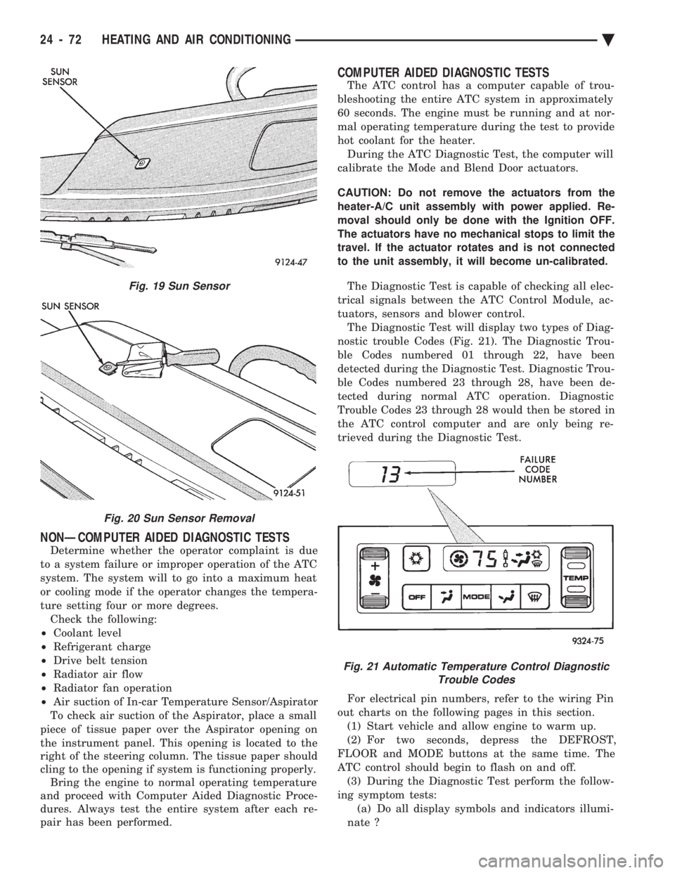
tuators, sensors and blower control. The Diagnostic Test will display two types of Diag-
nostic trouble Codes (Fig. 21). The Diagnostic Trou-
ble Codes numbered 01 through 22, have been
detected during the Diagnostic Test. Diagnostic Trou-
ble Codes numbered 23 through 28, have been de-
tected during normal ATC operation. Diagnostic
Trouble Codes 23 through 28 would then be stored in
the ATC control computer and are only being re-
trieved during the Diagnostic Test.
For electrical pin numbers, refer to the wiring Pin
out charts on the following pages in this section. (1) Start vehicle and allow engine to warm up.
(2) For two seconds, depress the DEFROST,
FLOOR and MODE buttons at the same time. The
ATC control should begin to flash on and off. (3) During the Diagnostic Test perform the follow-
ing symptom tests: (a) Do all display symbols and indicators illumi-
nate ?
Fig. 19 Sun Sensor
Fig. 20 Sun Sensor Removal
Fig. 21 Automatic Temperature Control Diagnostic Trouble Codes
24 - 72 HEATING AND AIR CONDITIONING Ä
Page 2377 of 2438
(b) Does the blower motor operate at its highest
speed ? (c) Feel the outlet temperature. Does it get hot
and then cycle cold ? (d) Does the air flow switch from DEFROST out-
lets and then cycle to PANEL outlets?
If you can answer NO to any of these questions,
proceed to step 4, otherwise proceed to step 5. (4) If you answered NO to:
SYMPTOM A
The display symbols and indicators do not illumi-
nate. Diagnostic Trouble Codes are not displayed.
TEST
After self-diagnostic test is complete, select a mode
that will display the malfunction.
ACTION
If the ATC system operates properly, and the dis-
play does not, replace ATC control panel computer.
SYMPTOM B
The blower motor does not operate.
CAUTION: Stay clear of blower motor and power
module (PM) heat sink. Do not run system for more
than 10 minutes with PM removed from A/C unit.
TEST Check all power module and blower motor connec-
tions. Use a voltmeter to test for 12 volts (ignition)
at both ends of the fuse with ignition ON. If fuse is
good, test the green wire at the blower motor connec-
tor for 12 volts (ignition) to body ground. Turn ignition to the ON position.
With the blower motor still connected, check for 12
volts to body ground on the black/tan wire of the
blower motor two way connector. Check for 12 volts at the Power Module pin #4
(BK/TN). Check for continuity from the Power Module pin
#3 (BK) to chassis ground. Replace the Power Module.
ACTION If 12 volts is not detected, repair feed circuit. Refer
to the Front Wheel Drive Car-Wiring Diagrams Ser-
vice Manual. If 12 volts is not detected, repair wires of the
blower motor or replace the blower motor. If 12 volts is not present, repair wire from the
blower motor connector to the Power Module. If circuit is open, repair ground circuit of the Power
Module. Replace the Power Module (power transistor open).
SYMPTOM C
The outlet air temperature does not become hot
and then cycle to cold during self-test operation. Di-
agnostic Trouble Codes are not displayed.
TEST/ACTION
Make sure the blend-air door is properly attached
to the actuator. If cold air is not discharged from the outlets, check
the base A/C refrigerant system. Make sure heating operation works correctly, (wa-
ter level, thermostat, heater hoses, heater core, etc.).
SYMPTOM D
Air does not flow from DEFROST outlets and then
cycle to PANEL outlets during self-test operation.
TEST/ACTION Check linkages from the mode door actuator for
binding. Check for proper door travel in the unit.
(5) The computer will do one of two things:
² Will return to the control settings that were se-
lected before the Diagnostic Test was started. This
means the test is over. If Diagnostic Trouble Codes
did not occur, and answers to questions (a), (b), (c),
and (d) were YES, the entire system is operating cor-
rectly.
² The blower motor will stop and the computer will
flash a Diagnostic Trouble Code number from 01
through 28. Record the number and then depress the
PANEL button to advance to the next test. If the
ATC control flashes one or more codes 23 to 28, the
digits on the display will flash alternating Zeros. If
you do nothing, these codes will remain stored within
the ATC control computer. After all repairs have
been made erase fault codes. Refer to Erasing Diag-
nostic Trouble Codes 23 through 28 from ATC Con-
trol in this section. Repair all Diagnostic Trouble Codes in the order
that they have been indicated, and then retest the
system. If any blend door test fails, all remaining
blend door tests will be skipped. IF any mode door
tests fail, all remaining mode door tests will be
skipped. Diagnostic Test can be stopped at any time by de-
pressing any button other than PANEL.
DIAGNOSTIC TROUBLE CODE DEFINITIONS
Non-computer aided diagnostics should be per-
formed first. Hood of vehicle should be closed during
the diagnostic test to keep engine heat from effecting
the ambient temperature sensor. Also refer to the wiring Pin out charts.
² DIAGNOSTIC TROUBLE CODE 1
Involves the wiring or the ATC control head.
² DIAGNOSTIC TROUBLE CODES 2, 13, 14, 15,
20, and 23
Ä HEATING AND AIR CONDITIONING 24 - 73