1993 CHEVROLET PLYMOUTH ACCLAIM ignition
[x] Cancel search: ignitionPage 1870 of 2438
3.0L MULTI-PORT FUEL INJECTIONÐON-BOARD DIAGNOSTICS INDEX
page page
60-Way PCM Wiring Connector ............. 136
Circuit Actuation Test Mode ................ 134
Diagnostic Trouble Code Description ......... 131
General Information ...................... 130
High and Low Limits ..................... 131
Ignition Timing Procedure ................. 136 Monitored Circuits
....................... 130
Non-Monitored Circuits ................... 131
State Display Test Mode .................. 134
System Tests .......................... 134
Throttle Body Minimum Air Flow Check Procedure ............................ 135
GENERAL INFORMATION
The PCM has been programmed to monitor many
different circuits of the fuel injection system. If a
problem is sensed with a monitored circuit often
enough to indicate an actual problem, the PCM
stores a fault. If the problem is repaired or ceases to
exist, the PCM cancels the Diagnostic trouble code
after 51 vehicle key on/off cycles. Certain criteria must be met for a diagnostic trou-
ble code to be entered into PCM memory. The crite-
ria may be a specific range of engine RPM, engine
temperature, and/or input voltage to the PCM. It is possible a diagnostic trouble code for a moni-
tored circuit may not be entered into memory even
though a malfunction has occurred. This may happen
because one of the diagnostic trouble code criteria for
the circuit has not been met. For example, assume
one of the diagnostic trouble code criteria for a cer-
tain sensor is the engine must be operating between
750 and 2000 RPM. If the sensor output circuit
shorts to ground when engine RPM is above 2400
RPM (resulting i n a 0 volt input to the PCM) a diag-
nostic trouble code will not be entered into memory.
This is because the condition does not occur within
the specified RPM range. There are several operating conditions that the
PCM does not monitor and set diagnostic trouble
codes for. Refer to Monitored Circuits and Non-Mon-
itored Circuits in this section. Stored diagnostic trouble codes can be displayed ei-
ther by cycling the ignition key On - Off - On - Off -
On, or through use of the DRBII scan tool. The
DRBII scan tool connects to the data link connector
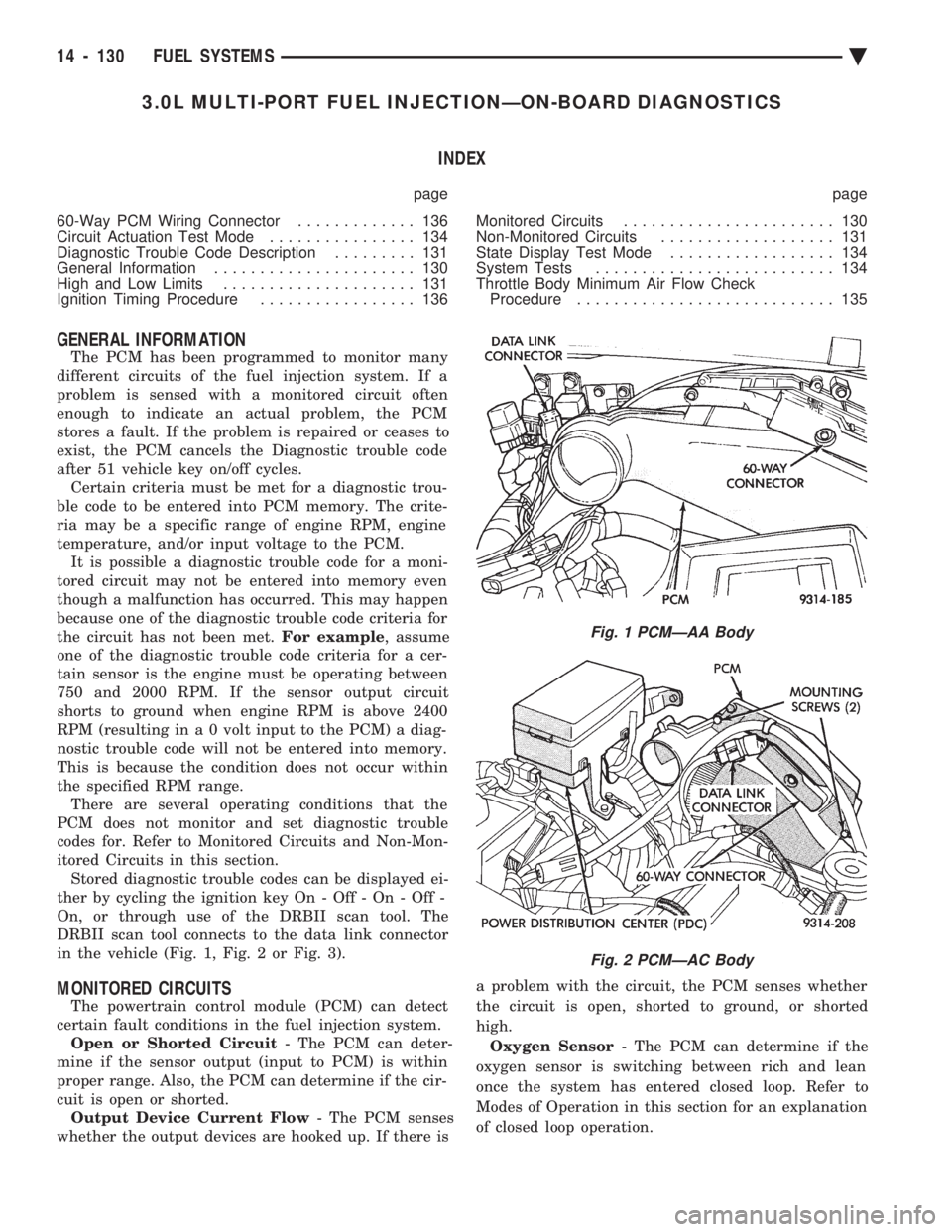
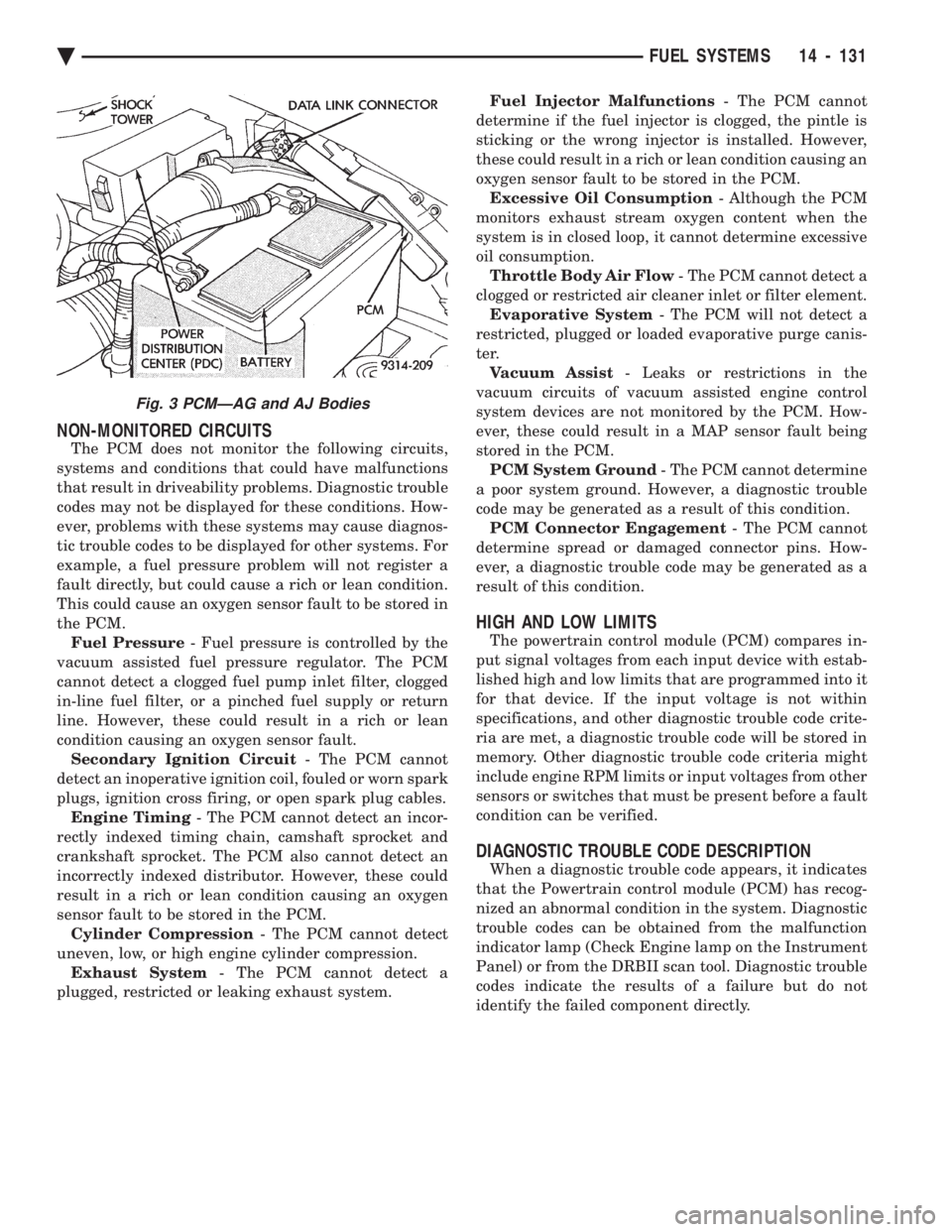
in the vehicle (Fig. 1, Fig. 2 or Fig. 3).
MONITORED CIRCUITS
The powertrain control module (PCM) can detect
certain fault conditions in the fuel injection system. Open or Shorted Circuit - The PCM can deter-
mine if the sensor output (input to PCM) is within
proper range. Also, the PCM can determine if the cir-
cuit is open or shorted. Output Device Current Flow - The PCM senses
whether the output devices are hooked up. If there is a problem with the circuit, the PCM senses whether
the circuit is open, shorted to ground, or shorted
high. Oxygen Sensor - The PCM can determine if the
oxygen sensor is switching between rich and lean
once the system has entered closed loop. Refer to
Modes of Operation in this section for an explanation
of closed loop operation.
Fig. 1 PCMÐAA Body
Fig. 2 PCMÐAC Body
14 - 130 FUEL SYSTEMS Ä
Page 1871 of 2438
NON-MONITORED CIRCUITS
The PCM does not monitor the following circuits,
systems and conditions that could have malfunctions
that result in driveability problems. Diagnostic trouble
codes may not be displayed for these conditions. How-
ever, problems with these systems may cause diagnos-
tic trouble codes to be displayed for other systems. For
example, a fuel pressure problem will not register a
fault directly, but could cause a rich or lean condition.
This could cause an oxygen sensor fault to be stored in
the PCM. Fuel Pressure - Fuel pressure is controlled by the
vacuum assisted fuel pressure regulator. The PCM
cannot detect a clogged fuel pump inlet filter, clogged
in-line fuel filter, or a pinched fuel supply or return
line. However, these could result in a rich or lean
condition causing an oxygen sensor fault. Secondary Ignition Circuit - The PCM cannot
detect an inoperative ignition coil, fouled or worn spark
plugs, ignition cross firing, or open spark plug cables. Engine Timing - The PCM cannot detect an incor-
rectly indexed timing chain, camshaft sprocket and
crankshaft sprocket. The PCM also cannot detect an
incorrectly indexed distributor. However, these could
result in a rich or lean condition causing an oxygen
sensor fault to be stored in the PCM. Cylinder Compression - The PCM cannot detect
uneven, low, or high engine cylinder compression. Exhaust System - The PCM cannot detect a
plugged, restricted or leaking exhaust system. Fuel Injector Malfunctions
- The PCM cannot
determine if the fuel injector is clogged, the pintle is
sticking or the wrong injector is installed. However,
these could result in a rich or lean condition causing an
oxygen sensor fault to be stored in the PCM. Excessive Oil Consumption - Although the PCM
monitors exhaust stream oxygen content when the
system is in closed loop, it cannot determine excessive
oil consumption. Throttle Body Air Flow - The PCM cannot detect a
clogged or restricted air cleaner inlet or filter element. Evaporative System - The PCM will not detect a
restricted, plugged or loaded evaporative purge canis-
ter. Vacuum Assist - Leaks or restrictions in the
vacuum circuits of vacuum assisted engine control
system devices are not monitored by the PCM. How-
ever, these could result in a MAP sensor fault being
stored in the PCM. PCM System Ground - The PCM cannot determine
a poor system ground. However, a diagnostic trouble
code may be generated as a result of this condition. PCM Connector Engagement - The PCM cannot
determine spread or damaged connector pins. How-
ever, a diagnostic trouble code may be generated as a
result of this condition.
HIGH AND LOW LIMITS
The powertrain control module (PCM) compares in-
put signal voltages from each input device with estab-
lished high and low limits that are programmed into it
for that device. If the input voltage is not within
specifications, and other diagnostic trouble code crite-
ria are met, a diagnostic trouble code will be stored in
memory. Other diagnostic trouble code criteria might
include engine RPM limits or input voltages from other
sensors or switches that must be present before a fault
condition can be verified.
DIAGNOSTIC TROUBLE CODE DESCRIPTION
When a diagnostic trouble code appears, it indicates
that the Powertrain control module (PCM) has recog-
nized an abnormal condition in the system. Diagnostic
trouble codes can be obtained from the malfunction
indicator lamp (Check Engine lamp on the Instrument
Panel) or from the DRBII scan tool. Diagnostic trouble
codes indicate the results of a failure but do not
identify the failed component directly.
Fig. 3 PCMÐAG and AJ Bodies
Ä FUEL SYSTEMS 14 - 131
Page 1874 of 2438
SYSTEM TESTS
WARNING: APPLY PARKING BRAKE AND/OR BLOCK
WHEELS BEFORE PERFORMING ANY TEST ON AN
OPERATING ENGINE.
OBTAINING DIAGNOSTIC TROUBLE CODES
(1) Connect DRBII scan tool to the data link connec-
tor located in the engine compartment near the pow-
ertrain control module (PCM). (2) Start the engine if possible, cycle the transaxle
selector and the A/Cswitch if applicable. Shut off the
engine. (3) Turn the ignition switch on, access Read Fault
Screen. Record all the fault messages shown on the
DRBII scan tool. Observe the malfunction indicator
lamp (Check Engine lamp on the instrument panel).
The lamp should light for 3 seconds then go out (bulb
check). Diagnostic trouble code erasure; access erase
diagnostic trouble code data
STATE DISPLAY TEST MODE
The switch inputs used by the powertrain control
module (PCM) have only two recognized states, HIGH
and LOW. For this reason, the PCM cannot recognize
the difference between a selected switch position ver-
sus an open circuit, a short circuit, or a defective
switch. If the change is displayed, it can be assumed
that the entire switch circuit to the PCM is functional.
From the state display screen access either State
Display Inputs and Outputs or State Display Sensors.
STATE DISPLAY INPUTS AND OUTPUTS
Connect the DRBII scan tool to the vehicle. Access
the State Display screen. Then access Inputs and
Outputs. The following is a list of the engine control
system functions accessible through the Inputs and
Outputs screen. Park/Neutral Switch
Speed Control Resume
Brake Switch
Speed Control On/Off
Speed Control Set
A/C Switch Sense
S/C Vent Solenoid
S/C Vacuum Solenoid
A/C Clutch Relay
EGR Solenoid
Auto Shutdown Relay
Radiator Fan Relay
Purge Solenoid
Torque Converter Clutch Solenoid
Malfunction Indicator Lamp (Check Engine Lamp)
STATE DISPLAY SENSORS
Connect the DRBII scan tool to the vehicle and ac-
cess the State Display screen. Then access Sensor
Display. The following is a list of the engine control
system functions accessible through the Sensor Dis-
play screen. Battery Temperature
Oxygen Sensor Signal
Engine Coolant Temperature
Engine Coolant Temp Sensor
Throttle Position
Minimum Throttle
Battery Voltage
MAP Sensor Reading
Idle Air Control Motor Position
Adaptive Fuel Factor
Barometric Pressure
Min Airflow Idle Speed
Engine Speed
Fault #1 Key-On Info
Module Spark Advance
Speed Control Target
Fault #2 Key-on Info
Fault #3 Key-on Info
Speed Control Status
Speed Control Switch Voltage
Charging System Goal
Theft Alarm Status
Map Sensor Voltage
Vehicle Speed
Oxygen Sensor State
MAP Gauge Reading
Throttle Opening (percentage)
Total Spark Advance
CIRCUIT ACTUATION TEST MODE
The circuit actuation test mode checks for proper
operation of output circuits or devices which the pow-
ertrain control module (PCM) cannot internally rec-
ognize. The PCM can attempt to activate these
outputs and allow an observer to verify proper oper-
ation. Most of the tests provide an audible or visual
indication of device operation (click of relay contacts,
spray fuel, etc.). Except for intermittent conditions, if
a device functions properly during testing, assume
the device, its associated wiring, and driver circuit
working correctly.
OBTAINING CIRCUIT ACTUATION TEST
Connect the DRBII scan tool to the vehicle and ac-
cess the Actuators screen. The following is a list of
the engine control system functions accessible
through Actuators screens. Stop All Tests
Ignition Coil #1
Fuel Injector #1
Fuel Injector #2
Fuel Injector #3
14 - 134 FUEL SYSTEMS Ä
Page 1876 of 2438
WARNING: CLEAN THROTTLE BODY IN A WELL
VENTILATED AREA. WEAR RUBBER OF BUTYL
GLOVES, DO NOT LET MOPAR PARTS CLEANER
COME IN CONTACT WITH EYES OR SKIN. AVOID
INGESTING THE CLEANER. WASH THOROUGHLY
AFTER USING CLEANER.
(b) While holding the throttle open, spray the
entire throttle body bore and the manifold side of the
throttle plate with Mopar Parts Cleaner. Only use
Mopar Parts Cleaner to clean the throttle body. (c) Using a soft scuff pad, clean the top and bottom
of throttle body bore and the edges and manifold side
of the throttle blade. The edges of the throttle
blade and portions of the throttle bore that are
closest to the throttle blade when is closed,
must be free of deposits. (d) Use compressed air to dry the throttle body.
(e) Inspect throttle body for foreign material. (f) Install throttle body on manifold.
(g) Repeat steps 1 through 14. If the minimum air
flow is still not within specifications, the problem is
not caused by the throttle body.
(16) Shut off engine.
(17) Remove Air Metering Fitting #6457 from the
intake manifold idle purge hose. Reconnect the hose to
the engine vacuum harness tee. (18) Remove the plug from the PCV valve. Reconnect
the PCV valve hose to the PCV valve. (19) Disconnect the DRBII scan tool.
IGNITION TIMING PROCEDURE
Refer to Group 8D Ignition System.
60-WAY PCM WIRING CONNECTOR
Refer to the PCM wiring connector description (Fig.
7) for information regarding wire colors and cavity
numbers.
14 - 136 FUEL SYSTEMS Ä
Page 1880 of 2438
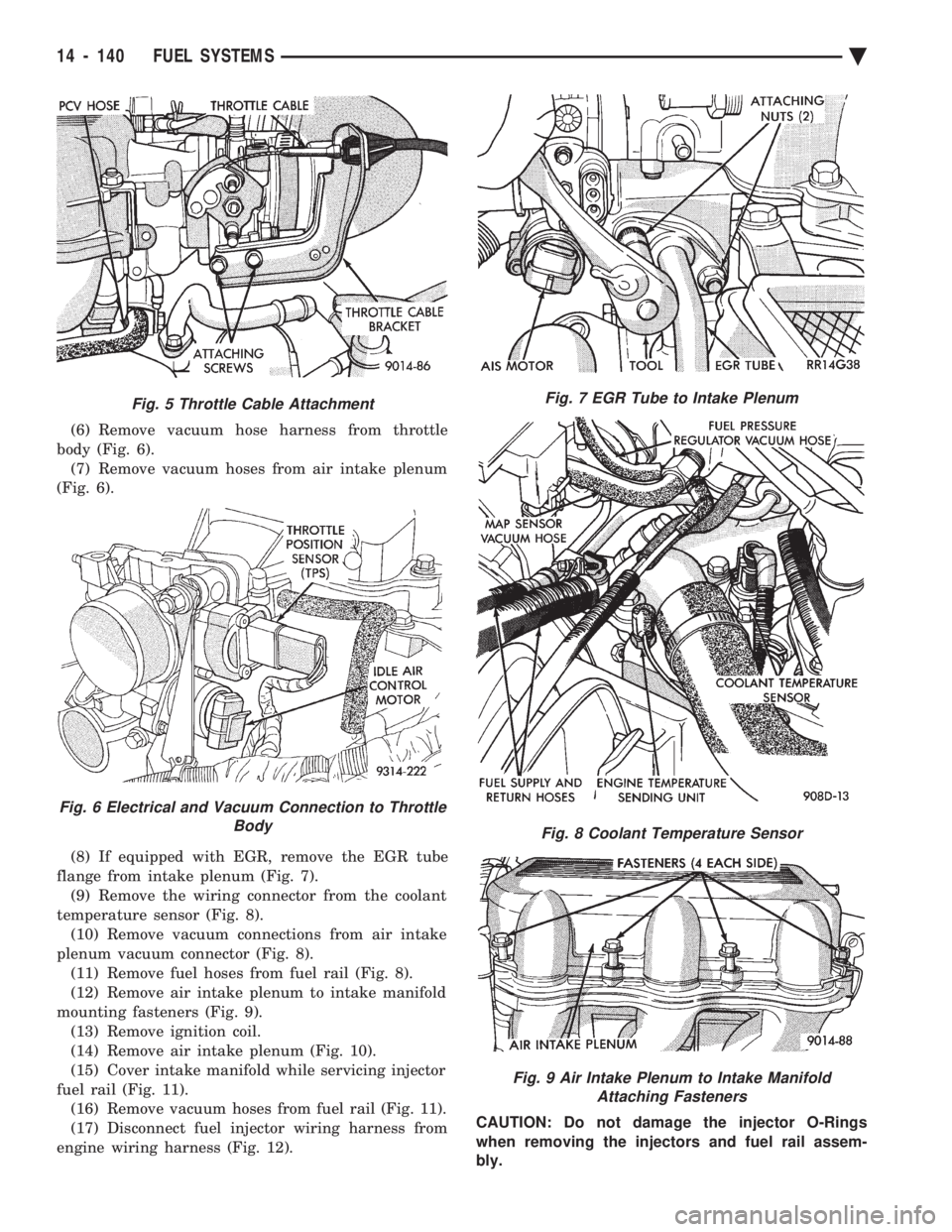
(6) Remove vacuum hose harness from throttle
body (Fig. 6). (7) Remove vacuum hoses from air intake plenum
(Fig. 6).
(8) If equipped with EGR, remove the EGR tube
flange from intake plenum (Fig. 7). (9) Remove the wiring connector from the coolant
temperature sensor (Fig. 8). (10) Remove vacuum connections from air intake
plenum vacuum connector (Fig. 8). (11) Remove fuel hoses from fuel rail (Fig. 8).
(12) Remove air intake plenum to intake manifold
mounting fasteners (Fig. 9). (13) Remove ignition coil.
(14) Remove air intake plenum (Fig. 10).
(15) Cover intake manifold while servicing injector
fuel rail (Fig. 11). (16) Remove vacuum hoses from fuel rail (Fig. 11).
(17) Disconnect fuel injector wiring harness from
engine wiring harness (Fig. 12). CAUTION: Do not damage the injector O-Rings
when removing the injectors and fuel rail assem-
bly.
Fig. 5 Throttle Cable Attachment
Fig. 6 Electrical and Vacuum Connection to Throttle Body
Fig. 7 EGR Tube to Intake Plenum
Fig. 8 Coolant Temperature Sensor
Fig. 9 Air Intake Plenum to Intake ManifoldAttaching Fasteners
14 - 140 FUEL SYSTEMS Ä
Page 1881 of 2438
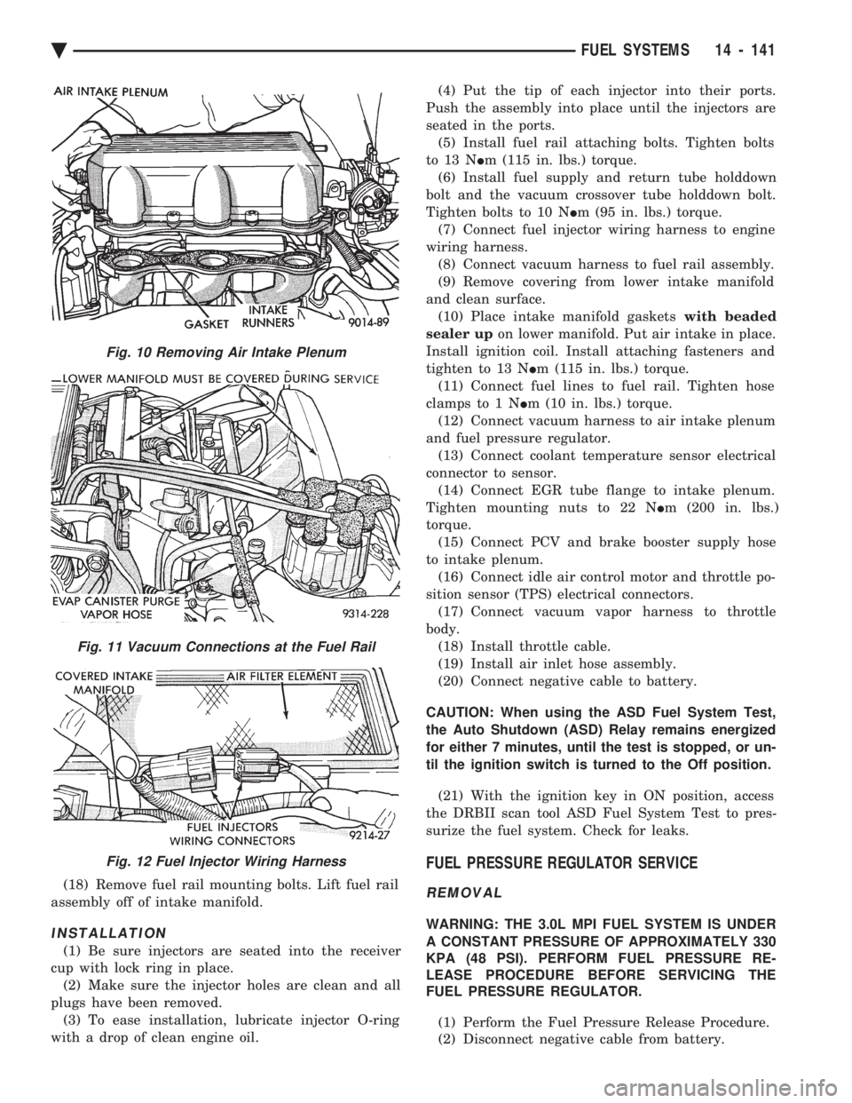
(18) Remove fuel rail mounting bolts. Lift fuel rail
assembly off of intake manifold.
INSTALLATION
(1) Be sure injectors are seated into the receiver
cup with lock ring in place. (2) Make sure the injector holes are clean and all
plugs have been removed. (3) To ease installation, lubricate injector O-ring
with a drop of clean engine oil. (4) Put the tip of each injector into their ports.
Push the assembly into place until the injectors are
seated in the ports. (5) Install fuel rail attaching bolts. Tighten bolts
to 13 N Im (115 in. lbs.) torque.
(6) Install fuel supply and return tube holddown
bolt and the vacuum crossover tube holddown bolt.
Tighten bolts to 10 N Im (95 in. lbs.) torque.
(7) Connect fuel injector wiring harness to engine
wiring harness. (8) Connect vacuum harness to fuel rail assembly.
(9) Remove covering from lower intake manifold
and clean surface. (10) Place intake manifold gaskets with beaded
sealer up on lower manifold. Put air intake in place.
Install ignition coil. Install attaching fasteners and
tighten to 13 N Im (115 in. lbs.) torque.
(11) Connect fuel lines to fuel rail. Tighten hose
clamps to 1 N Im (10 in. lbs.) torque.
(12) Connect vacuum harness to air intake plenum
and fuel pressure regulator. (13) Connect coolant temperature sensor electrical
connector to sensor. (14) Connect EGR tube flange to intake plenum.
Tighten mounting nuts to 22 N Im (200 in. lbs.)
torque. (15) Connect PCV and brake booster supply hose
to intake plenum. (16) Connect idle air control motor and throttle po-
sition sensor (TPS) electrical connectors. (17) Connect vacuum vapor harness to throttle
body. (18) Install throttle cable.
(19) Install air inlet hose assembly.
(20) Connect negative cable to battery.
CAUTION: When using the ASD Fuel System Test,
the Auto Shutdown (ASD) Relay remains energized
for either 7 minutes, until the test is stopped, or un-
til the ignition switch is turned to the Off position. (21) With the ignition key in ON position, access
the DRBII scan tool ASD Fuel System Test to pres-
surize the fuel system. Check for leaks.
FUEL PRESSURE REGULATOR SERVICE
REMOVAL
WARNING: THE 3.0L MPI FUEL SYSTEM IS UNDER
A CONSTANT PRESSURE OF APPROXIMATELY 330
KPA (48 PSI). PERFORM FUEL PRESSURE RE-
LEASE PROCEDURE BEFORE SERVICING THE
FUEL PRESSURE REGULATOR.
(1) Perform the Fuel Pressure Release Procedure.
(2) Disconnect negative cable from battery.
Fig. 10 Removing Air Intake Plenum
Fig. 11 Vacuum Connections at the Fuel Rail
Fig. 12 Fuel Injector Wiring Harness
Ä FUEL SYSTEMS 14 - 141
Page 1882 of 2438
(3) Loosen fuel return hose clamp and remove fuel
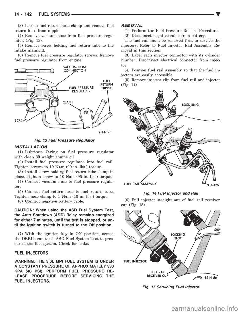
return hose from nipple. (4) Remove vacuum hose from fuel pressure regu-
lator. (Fig. 13). (5) Remove screw holding fuel return tube to the
intake manifold. (6) Remove fuel pressure regulator screws. Remove
fuel pressure regulator from engine.
INSTALLATION
(1) Lubricate O-ring on fuel pressure regulator
with clean 30 weight engine oil. (2) Install fuel pressure regulator into fuel rail.
Tighten screws to 10 N Im (90 in. lbs.) torque.
(3) Install screw holding fuel return tube clamp in
place. Tighten screw to 10 N Im (95 in. lbs.) torque.
(4) Connect vacuum hose to fuel pressure regula-
tor. (5) Connect fuel return hose to fuel return tube.
Tighten hose clamp to 1 N Im (10 in. lbs.) torque.
(6) Connect negative battery cable.
CAUTION: When using the ASD Fuel System Test,
the Auto Shutdown (ASD) Relay remains energized
for either 7 minutes, until the test is stopped, or un-
til the ignition switch is turned to the Off position.
(7) With the ignition key in ON position, access
the DRBII scan tool's ASD Fuel System Test to pres-
surize the fuel system. Check for leaks.
FUEL INJECTORS
WARNING: THE 3.0L MPI FUEL SYSTEM IS UNDER
A CONSTANT PRESSURE OF APPROXIMATELY 330
KPA (48 PSI). PERFORM FUEL PRESSURE RE-
LEASE PROCEDURE BEFORE SERVICING THE
FUEL INJECTORS.
REMOVAL
(1) Perform the Fuel Pressure Release Procedure.
(2) Disconnect negative cable from battery.
The fuel rail must be removed first to service the
injectors. Refer to Fuel Injector Rail Assembly Re-
moval in this section. (3) Label each injector connector with its cylinder
number. Disconnect electrical connector from injec-
tor. (4) Position fuel rail assembly so that the fuel in-
jectors are easily accessible. (5) Remove injector clip from fuel rail and injector
(Fig. 14).
(6) Pull injector straight out of fuel rail receiver
cup (Fig. 15).
Fig. 13 Fuel Pressure Regulator
Fig. 14 Fuel Injector and Rail
Fig. 15 Servicing Fuel Injector
14 - 142 FUEL SYSTEMS Ä
Page 1883 of 2438
(7) Check injector O-ring for damage. If O-ring is
damaged, it must be replaced. If injector is to be re-
used, a protective cap must be installed on the injec-
tor tip to prevent damage. (8) Repeat procedure for remaining injectors.
INSTALLATION
(1) Before installing an injector, the rubber O-ring
must be lubricated with a drop of clean engine oil to
aid in installation. (2) Being careful not to damage O-ring, install in-
jector nozzle end into fuel rail receiver cap (Fig. 15). (3) Install injector clip by sliding open end into top
slot of the injector. The edge of the receiver cup will
slide into the side slots of clip (Fig. 14). (4) Repeat steps for remaining injectors.
(5) Install fuel rail assembly. Refer to Fuel Rail
Assembly Installation in this section. (6) Connect electrical connectors to injectors in cor-
rect order. (7) Connect negative battery cable.
CAUTION: When using the ASD Fuel System Test,
the Auto Shutdown (ASD) Relay remains energized
for either 7 minutes, until the test is stopped, or un-
til the ignition switch is turned to the Off position.
(8) With the ignition key in ON position, access
the DRBII scan tool ASD Fuel System Test to pres-
surize the fuel system. Check for leaks.
MANIFOLD ABSOLUTE PRESSURE (MAP) SENSOR
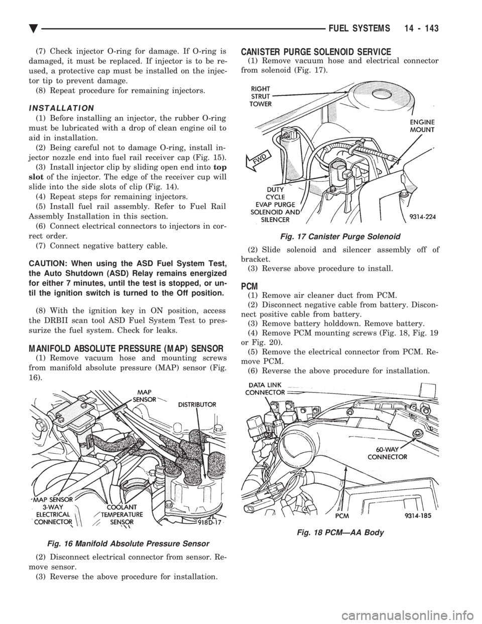
(1) Remove vacuum hose and mounting screws
from manifold absolute pressure (MAP) sensor (Fig.
16).
(2) Disconnect electrical connector from sensor. Re-
move sensor. (3) Reverse the above procedure for installation.
CANISTER PURGE SOLENOID SERVICE
(1) Remove vacuum hose and electrical connector
from solenoid (Fig. 17).
(2) Slide solenoid and silencer assembly off of
bracket. (3) Reverse above procedure to install.
PCM
(1) Remove air cleaner duct from PCM.
(2) Disconnect negative cable from battery. Discon-
nect positive cable from battery. (3) Remove battery holddown. Remove battery.
(4) Remove PCM mounting screws (Fig. 18, Fig. 19
or Fig. 20). (5) Remove the electrical connector from PCM. Re-
move PCM. (6) Reverse the above procedure for installation.
Fig. 16 Manifold Absolute Pressure Sensor
Fig. 17 Canister Purge Solenoid
Fig. 18 PCMÐAA Body
Ä FUEL SYSTEMS 14 - 143