1993 CHEVROLET PLYMOUTH ACCLAIM ignition
[x] Cancel search: ignitionPage 1919 of 2438
STEERING
CONTENTS
page page
ACUSTAR STANDARD AND TILT STEERING COLUMN ............................ 28
AUTOMATIC TRANSMISSION SHIFTER/IGNITION INTERLOCK .......................... 36
GENERAL INFORMATION .................. 1 POWER STEERING GEAR
................ 25
POWER STEERING PUMPS ................ 1
SPECIFICATIONS AND TIGHTENING REFERENCE .......................... 42
GENERAL INFORMATION
Safety goggles should be worn at all times
when working on any steering gear or pump. Throughout this group, references may be made to
a particular vehicle by letter or number designation.
A chart showing the breakdown of these designations
is included in the Introduction Section at the front of
this service manual. The power steering system consists of these four
major components. Power Steering Pump, Power
Steering Gear, Pressure Hose, and Return Line.
Turning of the steering wheel is converted into lin-
ear travel through the meshing of the helical pinion teeth with the rack teeth. Power assist steering is
provided by an open center, rotary type control valve.
It is used to direct oil from the power steering pump
to either side of the integral steering rack piston. Road feel is controlled by the diameter of a torsion
bar which initially steers the vehicle. As steering ef-
fort increases as in a turn, the torsion bar twists,
causing relative rotary motion between the rotary
valve body and valve spool. This movement directs
oil behind the integral rack piston, which in turn,
builds up hydraulic pressure and assists in the turn-
ing effort.
POWER STEERING PUMPS
INDEX
page page
Checking Power Steering Fluid Level .......... 9
Flow Control Valve Fitting O-Ring Seal ........ 23
General Information ........................ 1
Power Steering Hoses ..................... 11
Power Steering Pressure Switch ............. 10
Power Steering Pump Fluid Reservoirs ........ 22 Power Steering Pump Pressure Test
........... 9
Power Steering Pump Pulley Service .......... 20
Power Steering Pump Removal .............. 12
Power Steering Pump Service ................ 2
Power Steering PumpÐInitial Operation ....... 24
Steering Components Service Diagnosis ........ 2
GENERAL INFORMATION
Hydraulic pressure for operation of the power
steering gear is provided by a belt driven power
steering pump. The power steering pump is a con-
stant flow rate and displacement, vane type pump.
Different styles of Saginaw power steering pumps are
used depending on the engine application of the ve-
hicle. On all four cylinder and 3.0-liter V-6 applications
the Saginaw Ham Can power steering pump is used
(Fig. 1). On the 3.3 & 3.8-liter V-6 and Turbo III applica-
tions, different versions of the Saginaw T/C style
power steering pump is used (Fig. 2). The 3.3 & 3.8 liter V-6 engine application uses the T/C style power
steering pump with a remote mounted reservoir for
the power steering fluid. On the Turbo III application
of the T/C style power steering pump, the power
steering fluid reservoir is integral to the power steer-
ing pump. On the integral reservoir type pump (Fig. 1) the
pump housing and internal components are combined
with the reservoir to form a one-piece mechanism. The Saginaw T/C style power steering pump (Fig.
2), consists of the power steering pump internal com-
ponents and pump housing. The Saginaw T/C style
power steering pump though has no internal reser-
voir for the power steering fluid. Depending on vehi-
Ä STEERING 19 - 1
Page 1946 of 2438
ACUSTAR STANDARD AND TILT STEERING COLUMN INDEX
page page
General Information ....................... 28
Ignition Switch Service .................... 34 Steering Column Component Service
......... 34
Steering Column Service Procedures .......... 30
GENERAL INFORMATION
WARNING: THE AIR BAG SYSTEM IS A SENSITIVE,
COMPLEX ELECTRO-MECHANICAL UNIT. BEFORE
ATTEMPTING TO DIAGNOSE, REMOVE OR IN-
STALL THE AIR BAG SYSTEM COMPONENTS YOU
MUST FIRST DISCONNECT AND ISOLATE THE
BATTERY NEGATIVE (GROUND) CABLE. FAILURE
TO DO SO COULD RESULT IN ACCIDENTAL DE-
PLOYMENT OF THE AIR BAG AND POSSIBLE PER-
SONAL INJURY. THE FASTENERS, SCREWS, AND BOLTS, ORIGI-
NALLY USED FOR THE AIR BAG COMPONENTS,
HAVE SPECIAL COATINGS AND ARE SPECIFI- CALLY DESIGNED FOR THE AIR BAG SYSTEM.
THEY MUST NEVER BE REPLACED WITH ANY
SUBSTITUTES. ANYTIME A NEW FASTENER IS
NEEDED, REPLACE WITH THE CORRECT FASTEN-
ERS PROVIDED IN THE SERVICE PACKAGE OR
FASTENERS LISTED IN THE PARTS BOOKS. BEFORE SERVICING A STEERING COLUMN
EQUIPPED WITH AN AIR BAG, REFER TO GROUP
8M, ELECTRICAL FOR PROPER AND SAFE SER-
VICE PROCEDURES.
Safety goggles should be worn at all times
when working on steering columns.
19 - 28 STEERING Ä
Page 1949 of 2438
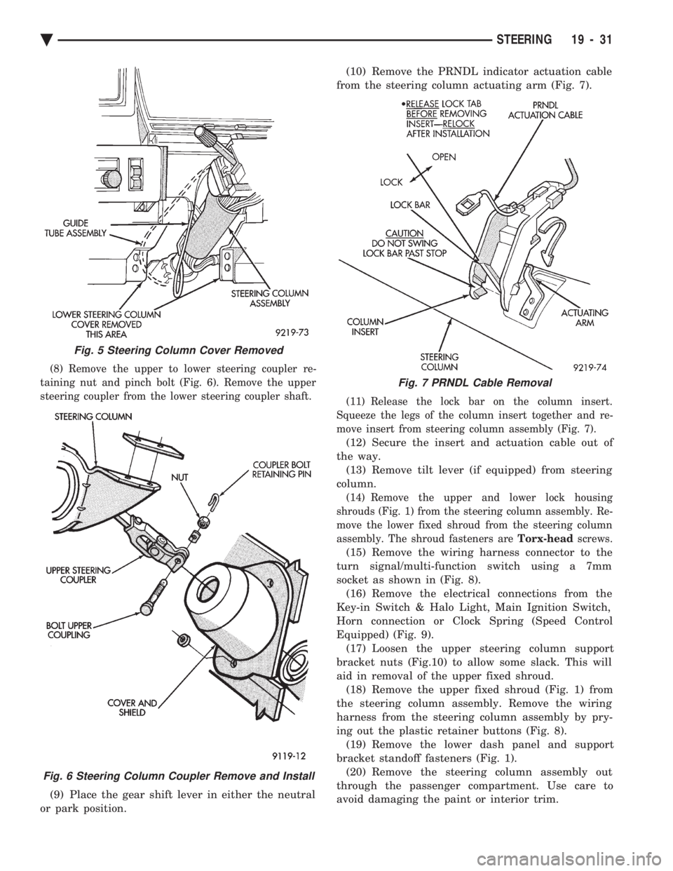
(8) Remove the upper to lower steering coupler re-
taining nut and pinch bolt (Fig. 6). Remove the upper
steering coupler from the lower steering coupler shaft.
(9) Place the gear shift lever in either the neutral
or park position. (10) Remove the PRNDL indicator actuation cable
from the steering column actuating arm (Fig. 7).
(11) Release the lock bar on the column insert.
Squeeze the legs of the column insert together and re-
move insert from steering column assembly (Fig. 7).
(12) Secure the insert and actuation cable out of
the way. (13) Remove tilt lever (if equipped) from steering
column.
(14) Remove the upper and lower lock housing
shrouds (Fig. 1) from the steering column assembly. Re-
move the lower fixed shroud from the steering column
assembly. The shroud fasteners are Torx-headscrews.
(15) Remove the wiring harness connector to the
turn signal/multi-function switch using a 7mm
socket as shown in (Fig. 8). (16) Remove the electrical connections from the
Key-in Switch & Halo Light, Main Ignition Switch,
Horn connection or Clock Spring (Speed Control
Equipped) (Fig. 9). (17) Loosen the upper steering column support
bracket nuts (Fig.10) to allow some slack. This will
aid in removal of the upper fixed shroud. (18) Remove the upper fixed shroud (Fig. 1) from
the steering column assembly. Remove the wiring
harness from the steering column assembly by pry-
ing out the plastic retainer buttons (Fig. 8). (19) Remove the lower dash panel and support
bracket standoff fasteners (Fig. 1). (20) Remove the steering column assembly out
through the passenger compartment. Use care to
avoid damaging the paint or interior trim.
Fig. 5 Steering Column Cover Removed
Fig. 6 Steering Column Coupler Remove and Install
Fig. 7 PRNDL Cable Removal
Ä STEERING 19 - 31
Page 1952 of 2438
(16) Connect the battery ground (negative) cable.
Test the operation of the lights and horns. If applica-
ble, reset the clock and radio.
STEERING COLUMN COMPONENT SERVICE
The Acustar tilt and standard steering columns
(Fig.1) have been designed to be serviced as an as-
sembly; less wiring, switches, shrouds, steering
wheel, etc. Also most steering column components
can be serviced without removing the steering col-
umn from the vehicle. For additional information on
electrical components refer to Group 8H Electrical.
GEAR SHIFT LEVER
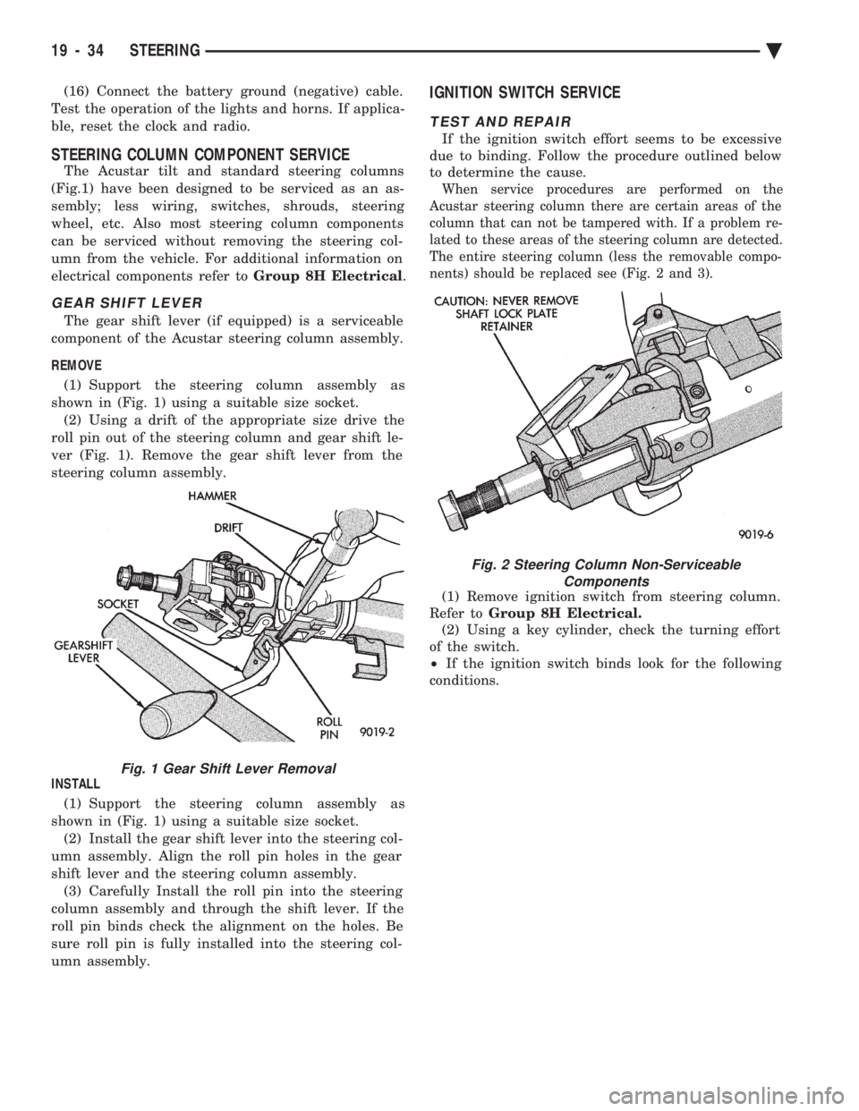
The gear shift lever (if equipped) is a serviceable
component of the Acustar steering column assembly.
REMOVE (1) Support the steering column assembly as
shown in (Fig. 1) using a suitable size socket. (2) Using a drift of the appropriate size drive the
roll pin out of the steering column and gear shift le-
ver (Fig. 1). Remove the gear shift lever from the
steering column assembly.
INSTALL (1) Support the steering column assembly as
shown in (Fig. 1) using a suitable size socket. (2) Install the gear shift lever into the steering col-
umn assembly. Align the roll pin holes in the gear
shift lever and the steering column assembly. (3) Carefully Install the roll pin into the steering
column assembly and through the shift lever. If the
roll pin binds check the alignment on the holes. Be
sure roll pin is fully installed into the steering col-
umn assembly.
IGNITION SWITCH SERVICE
TEST AND REPAIR
If the ignition switch effort seems to be excessive
due to binding. Follow the procedure outlined below
to determine the cause.
When service procedures are performed on the
Acustar steering column there are certain areas of the
column that can not be tampered with. If a problem re-
lated to these areas of the steering column are detected.
The entire steering column (less the removable compo-
nents) should be replaced see (Fig. 2 and 3).
(1) Remove ignition switch from steering column.
Refer to Group 8H Electrical.
(2) Using a key cylinder, check the turning effort
of the switch.
² If the ignition switch binds look for the following
conditions.
Fig. 1 Gear Shift Lever Removal
Fig. 2 Steering Column Non-Serviceable Components
19 - 34 STEERING Ä
Page 1953 of 2438
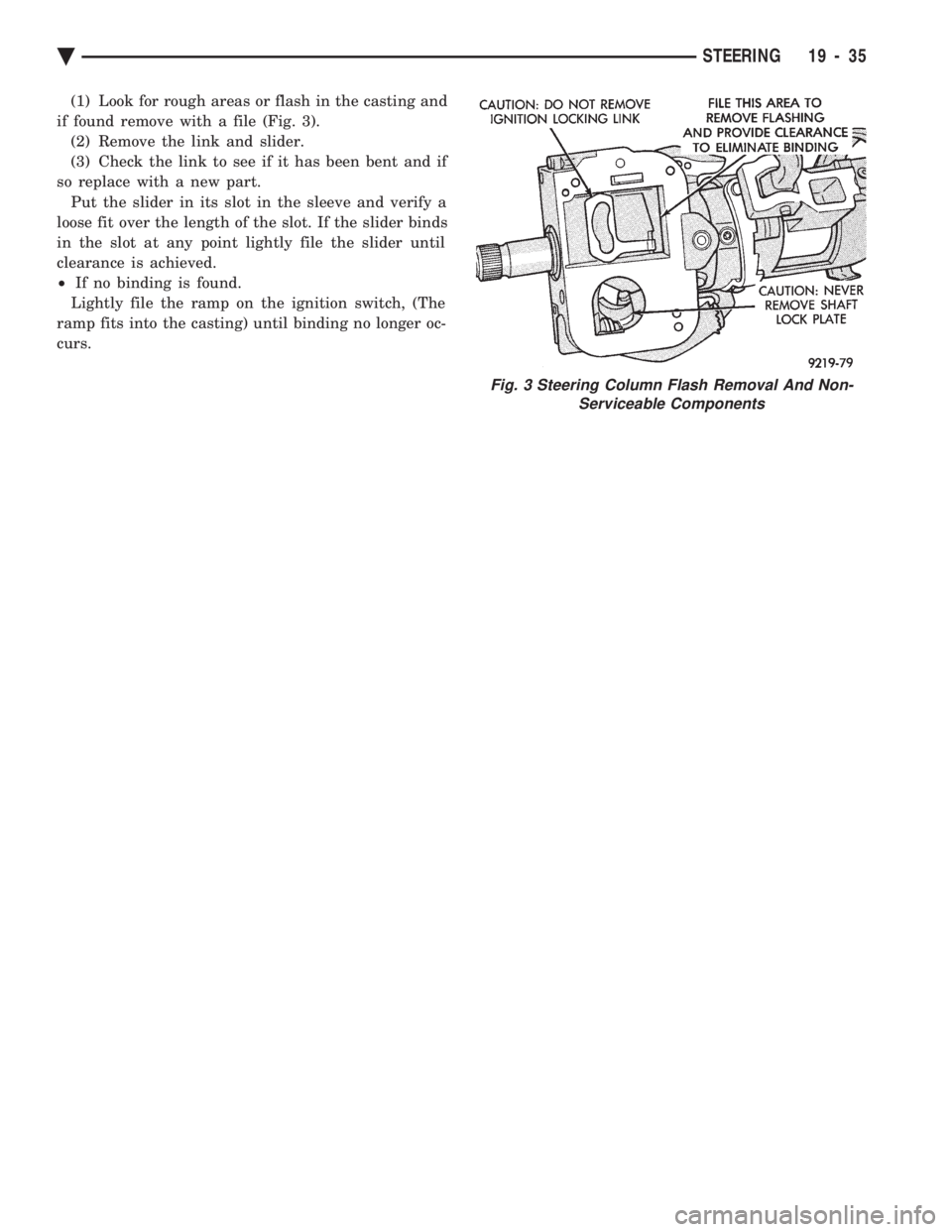
(1) Look for rough areas or flash in the casting and
if found remove with a file (Fig. 3). (2) Remove the link and slider.
(3) Check the link to see if it has been bent and if
so replace with a new part. Put the slider in its slot in the sleeve and verify a
loose fit over the length of the slot. If the slider binds
in the slot at any point lightly file the slider until
clearance is achieved.
² If no binding is found.
Lightly file the ramp on the ignition switch, (The
ramp fits into the casting) until binding no longer oc-
curs.
Fig. 3 Steering Column Flash Removal And Non- Serviceable Components
Ä STEERING 19 - 35
Page 1954 of 2438
AUTOMATIC TRANSMISSION SHIFTER/IGNITION INTERLOCK INDEX
page page
General Information ....................... 36
Interlock System Adjustment ................ 37 Interlock System Operation Check
............ 36
Shifter/Ignition Interlock Cable ............... 38
GENERAL INFORMATION
The automatic transmission Shifter/Ignition Inter-
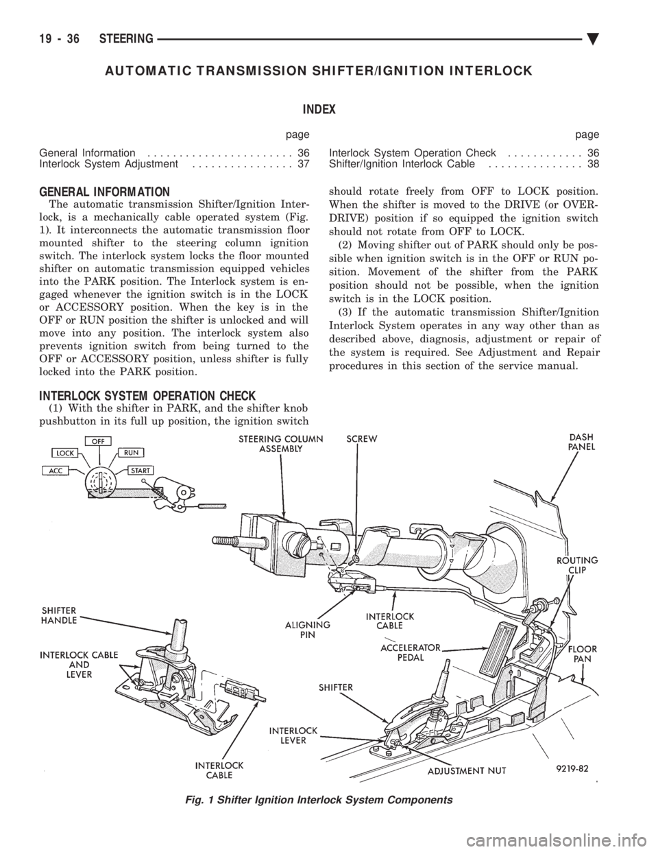
lock, is a mechanically cable operated system (Fig.
1). It interconnects the automatic transmission floor
mounted shifter to the steering column ignition
switch. The interlock system locks the floor mounted
shifter on automatic transmission equipped vehicles
into the PARK position. The Interlock system is en-
gaged whenever the ignition switch is in the LOCK
or ACCESSORY position. When the key is in the
OFF or RUN position the shifter is unlocked and will
move into any position. The interlock system also
prevents ignition switch from being turned to the
OFF or ACCESSORY position, unless shifter is fully
locked into the PARK position.
INTERLOCK SYSTEM OPERATION CHECK
(1) With the shifter in PARK, and the shifter knob
pushbutton in its full up position, the ignition switch should rotate freely from OFF to LOCK position.
When the shifter is moved to the DRIVE (or OVER-
DRIVE) position if so equipped the ignition switch
should not rotate from OFF to LOCK. (2) Moving shifter out of PARK should only be pos-
sible when ignition switch is in the OFF or RUN po-
sition. Movement of the shifter from the PARK
position should not be possible, when the ignition
switch is in the LOCK position. (3) If the automatic transmission Shifter/Ignition
Interlock System operates in any way other than as
described above, diagnosis, adjustment or repair of
the system is required. See Adjustment and Repair
procedures in this section of the service manual.
Fig. 1 Shifter Ignition Interlock System Components
19 - 36 STEERING Ä
Page 1955 of 2438
INTERLOCK SYSTEM ADJUSTMENT
If ignition switch is binding, operating effort high or
can not be turned to the LOCK position, with shifter locked
in PARK, adjustment of Interlock System may be
required. To adjust Interlock System, follow procedure
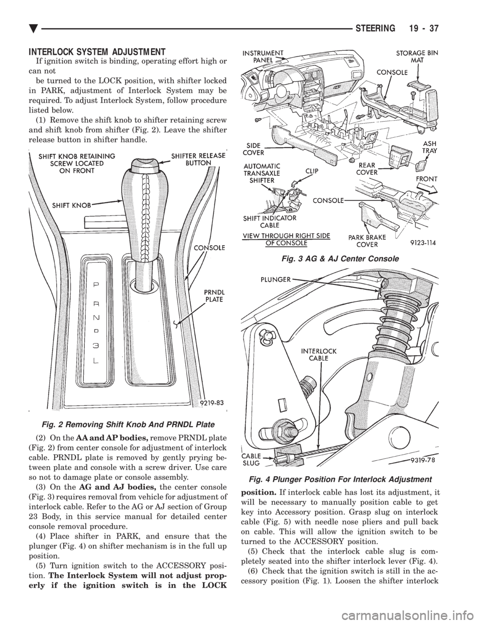
listed below. (1) Remove the shift knob to shifter retaining screw
and shift knob from shifter (Fig. 2). Leave the shifter
release button in shifter handle.
(2) On the AA and AP bodies, remove PRNDL plate
(Fig. 2) from center console for adjustment of interlock
cable. PRNDL plate is removed by gently prying be-
tween plate and console with a screw driver. Use care
so not to damage plate or console assembly. (3) On the AG and AJ bodies, the center console
(Fig. 3) requires removal from vehicle for adjustment of
interlock cable. Refer to the AG or AJ section of Group
23 Body, in this service manual for detailed center
console removal procedure. (4) Place shifter in PARK, and ensure that the
plunger (Fig. 4) on shifter mechanism is in the full up
position. (5) Turn ignition switch to the ACCESSORY posi-
tion. The Interlock System will not adjust prop-
erly if the ignition switch is in the LOCK position.
If interlock cable has lost its adjustment, it
will be necessary to manually position cable to get
key into Accessory position. Grasp slug on interlock
cable (Fig. 5) with needle nose pliers and pull back
on cable. This will allow the ignition switch to be
turned to the ACCESSORY position. (5) Check that the interlock cable slug is com-
pletely seated into the shifter interlock lever (Fig. 4). (6) Check that the ignition switch is still in the ac-
cessory position (Fig. 1). Loosen the shifter interlock
Fig. 3 AG & AJ Center Console
Fig. 4 Plunger Position For Interlock Adjustment
Fig. 2 Removing Shift Knob And PRNDL Plate
Ä STEERING 19 - 37
Page 1956 of 2438
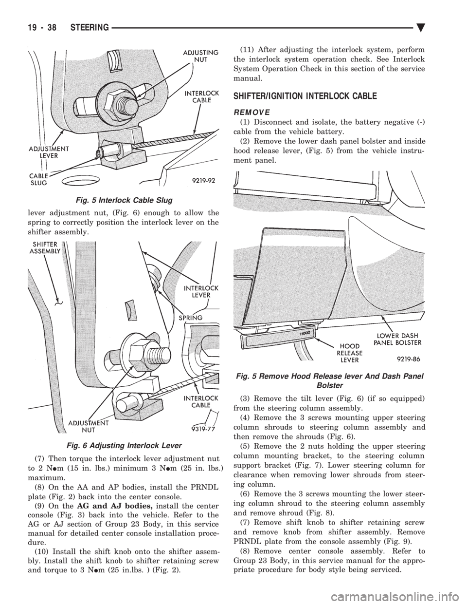
lever adjustment nut, (Fig. 6) enough to allow the
spring to correctly position the interlock lever on the
shifter assembly.
(7) Then torque the interlock lever adjustment nut
to2N Im (15 in. lbs.) minimum 3 N Im (25 in. lbs.)
maximum. (8) On the AA and AP bodies, install the PRNDL
plate (Fig. 2) back into the center console. (9) On the AG and AJ bodies, install the center
console (Fig. 3) back into the vehicle. Refer to the
AG or AJ section of Group 23 Body, in this service
manual for detailed center console installation proce-
dure. (10) Install the shift knob onto the shifter assem-
bly. Install the shift knob to shifter retaining screw
and torque to 3 N Im (25 in.lbs. ) (Fig. 2). (11) After adjusting the interlock system, perform
the interlock system operation check. See Interlock
System Operation Check in this section of the service
manual.
SHIFTER/IGNITION INTERLOCK CABLE
REMOVE
(1) Disconnect and isolate, the battery negative (-)
cable from the vehicle battery. (2) Remove the lower dash panel bolster and inside
hood release lever, (Fig. 5) from the vehicle instru-
ment panel.
(3) Remove the tilt lever (Fig. 6) (if so equipped)
from the steering column assembly. (4) Remove the 3 screws mounting upper steering
column shrouds to steering column assembly and
then remove the shrouds (Fig. 6). (5) Remove the 2 nuts holding the upper steering
column mounting bracket, to the steering column
support bracket (Fig. 7). Lower steering column for
clearance when removing lower shrouds from steer-
ing column. (6) Remove the 3 screws mounting the lower steer-
ing column shroud to the steering column assembly
and remove shroud (Fig. 8). (7) Remove shift knob to shifter retaining screw
and remove knob from shifter assembly. Remove
PRNDL plate from the console assembly (Fig. 9). (8) Remove center console assembly. Refer to
Group 23 Body, in this service manual for the appro-
priate procedure for body style being serviced.
Fig. 5 Interlock Cable Slug
Fig. 6 Adjusting Interlock Lever
Fig. 5 Remove Hood Release lever And Dash Panel Bolster
19 - 38 STEERING Ä