1993 CHEVROLET PLYMOUTH ACCLAIM jump cable
[x] Cancel search: jump cablePage 383 of 2438

STARTER TEST PROCEDURES ON VEHICLE INDEX
page page
Diagnostic Preparation ..................... 11
General Information ....................... 11 Starter Control Circuit Tests
................ 15
Starter Feed Circuit Tests .................. 11
GENERAL INFORMATION
The starting system (Fig. 1) has:
² Ignition switch
² Starter relay (Fig. 2)
² Neutral starting and back-up switch with auto-
matic transmissions
² Clutch pedal mounted starter interlock switch
with manual transmissions
² Wiring harness
² Battery
² Starter motor with an integral solenoid
These components form two separate circuits. A
high amperage circuit that feeds the starter motor up
to 300+ amps, and a control circuit that operates on
less than 20 amps.
DIAGNOSTIC PREPARATION
Before going on with starting system diagnostics,
verify: (1) The battery top, posts, and terminals are clean.
(2) The generator drive belt tension and condition
is correct. (3) The battery state-of-charge is correct.
(4) The battery will pass load test.
(5) The battery cable connections at the starter
and engine block are clean and free from corrosion. (6) The wiring harness connectors and terminals
are clean and free from corrosion. (7) Proper circuit grounding.
(8) Refer to Starter System Diagnostics (Fig. 3).
STARTER FEED CIRCUIT TESTS
The following procedure will require a suitable
volt/ampere tester (Fig. 4).
CAUTION: Ignition system also must be disabled to
prevent engine start while performing the following
tests.
(1) Connect a volt-ampere tester (Fig. 4) to the bat-
tery terminals (Fig. 5). Refer to the operating in-
structions provided with the tester being used. (2) Disable ignition system as follows:
² VEHICLES WITH CONVENTIONAL DISTRIBU-
TORS: Disconnect the ignition coil cable from the
distributor cap. Connect a suitable jumper wire be-
tween the coil cable end-terminal and a good body
ground (Fig. 6).
Fig. 1 Starting Components/Wiring
Fig. 2 Starter Relay
Ä BATTERY/STARTING/CHARGING SYSTEMS DIAGNOSTICS 8A - 11
Page 386 of 2438
STARTER FEED CIRCUIT RESISTANCE TEST
Before going on with this operation, review Diag-
nostic Preparation and Starter Feed Circuit Tests.
The following operation will require a voltmeter, ac-
curate to 1/10 of a volt.
CAUTION: Ignition system also must be disabled to
prevent engine start while performing the following
tests.
(1) Disable ignition system as follows:
² VEHICLES WITH CONVENTIONAL DISTRIBU-
TORS: Disconnect the ignition coil cable from the
distributor cap. Connect a suitable jumper wire be-
tween the coil cable end-terminal and a good body
ground (Fig. 6).
² VEHICLES WITH DIRECT IGNITION SYSTEM:
Disconnect the ignition coils electrical connector (Fig.
7). (2) With all wiring harnesses and components
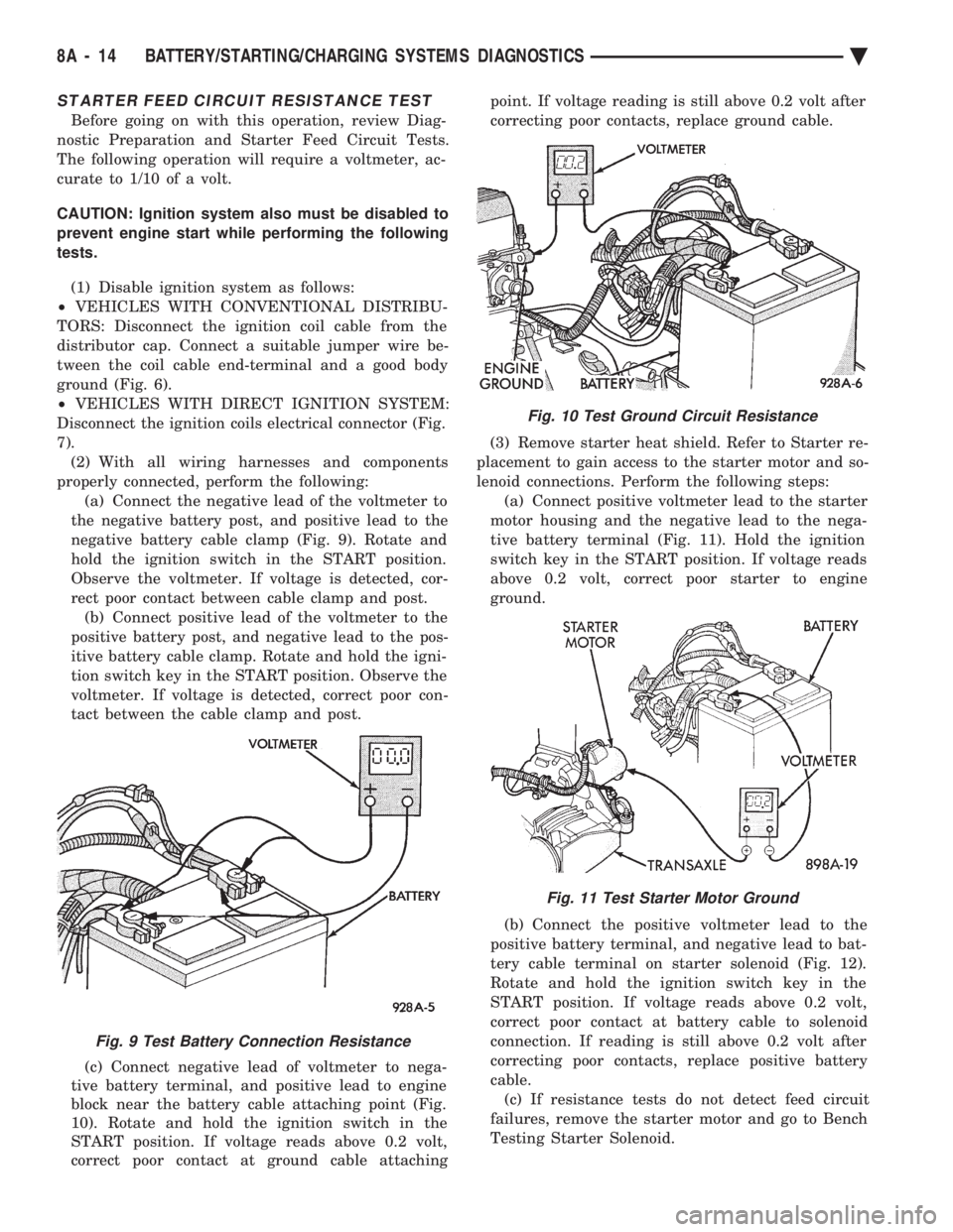
properly connected, perform the following: (a) Connect the negative lead of the voltmeter to
the negative battery post, and positive lead to the
negative battery cable clamp (Fig. 9). Rotate and
hold the ignition switch in the START position.
Observe the voltmeter. If voltage is detected, cor-
rect poor contact between cable clamp and post. (b) Connect positive lead of the voltmeter to the
positive battery post, and negative lead to the pos-
itive battery cable clamp. Rotate and hold the igni-
tion switch key in the START position. Observe the
voltmeter. If voltage is detected, correct poor con-
tact between the cable clamp and post.
(c) Connect negative lead of voltmeter to nega-
tive battery terminal, and positive lead to engine
block near the battery cable attaching point (Fig.
10). Rotate and hold the ignition switch in the
START position. If voltage reads above 0.2 volt,
correct poor contact at ground cable attaching point. If voltage reading is still above 0.2 volt after
correcting poor contacts, replace ground cable.
(3) Remove starter heat shield. Refer to Starter re-
placement to gain access to the starter motor and so-
lenoid connections. Perform the following steps: (a) Connect positive voltmeter lead to the starter
motor housing and the negative lead to the nega-
tive battery terminal (Fig. 11). Hold the ignition
switch key in the START position. If voltage reads
above 0.2 volt, correct poor starter to engine
ground.
(b) Connect the positive voltmeter lead to the
positive battery terminal, and negative lead to bat-
tery cable terminal on starter solenoid (Fig. 12).
Rotate and hold the ignition switch key in the
START position. If voltage reads above 0.2 volt,
correct poor contact at battery cable to solenoid
connection. If reading is still above 0.2 volt after
correcting poor contacts, replace positive battery
cable. (c) If resistance tests do not detect feed circuit
failures, remove the starter motor and go to Bench
Testing Starter Solenoid.
Fig. 9 Test Battery Connection Resistance
Fig. 10 Test Ground Circuit Resistance
Fig. 11 Test Starter Motor Ground
8A - 14 BATTERY/STARTING/CHARGING SYSTEMS DIAGNOSTICS Ä
Page 387 of 2438

STARTER CONTROL CIRCUIT TESTS
The starter control circuit has:
² Starter solenoid
² Starter relay (Fig. 2)
² Neutral starting and back-up switch with auto-
matic transmissions
² Clutch pedal mounted starter interlock switch
with manual transmissions
² Ignition switch
² Battery
² All related wiring and connections
CAUTION: Before performing any starter tests, the
ignition system must be disabled.
² VEHICLES EQUIPPED WITH A CONVEN-
TIONAL DISTRIBUTOR: Disconnect coil wire from
distributor cap center tower. Secure wire to a good
ground to prevent engine from starting (Fig. 6).
² VEHICLES EQUIPPED WITH DIRECT IGNI-
TION SYSTEM: Unplug the coils electrical connector
(Fig. 7).
STARTER SOLENOID TEST
WARNING: CHECK TO ENSURE THAT THE TRANS-
MISSION IS IN PARK OR NEUTRAL WITH THE
PARKING BRAKE APPLIED
(1) Verify battery condition. Battery must be in
good condition with a full charge before performing
any starter tests. Refer to Battery Tests. (2) Perform this starter solenoid test BEFORE per-
forming the starter relay test. (3) Raise the vehicle.
(4) Perform a visual inspection of the starter/
starter solenoid for corrosion, loose connections or
faulty wiring. (5) Lower the vehicle.
(6) Locate the starter relay as follows:
² On AC, AG, AJ and AY Bodies the relay is located
in the Power Distribution Center. This Center is mounted near the front of the left front strut tower
(Fig. 13). The position of the starter relay within this
Center will be shown on the Center cover.
² On AA/AP Bodies the relay is located on the front
of the left front strut tower (Fig. 14).
(7) Remove the starter relay from the connector.
(8) Connect a remote starter switch or a jumper
wire between the battery positive post and terminal
87 on the starter relay connector. To decide the
starter relay terminal numbers, refer to the Starter
Relay Tests.
² If engine now cranks, starter/starter solenoid is
good. Go to the starter relay test.
² If engine does not crank with this test, or solenoid
chatters, check wiring and connectors from starter
Fig. 12 Test Positive Battery Cable Resistance
Fig. 13 Starter Relay LocationÐAC, AG, AJ, and AY Bodies
Fig. 14 Starter Relay LocationÐAA/AP Body
Ä BATTERY/STARTING/CHARGING SYSTEMS DIAGNOSTICS 8A - 15
Page 391 of 2438
GENERATOR TEST PROCEDURES ON VEHICLE INDEX
page page
Charging System Diagnostics (Fig. 1) ......... 19
Current Output Test ...................... 19 Output Wire Resistance Test
................ 19
CHARGING SYSTEM DIAGNOSTICS (Fig. 1)
OUTPUT WIRE RESISTANCE TEST
The generator output wire resistance test shows
the amount of voltage drop across the generator out-
put wire between the generator B+ terminal and the
positive battery post.
PREPARATION
Before starting test, make sure the vehicle has a
fully charged battery. Tests and procedures to check
for a fully charged battery is shown in the Battery
section. (1) Turn the ignition switch OFF.
(2) Disconnect battery NEGATIVE cable.
(3) Disconnect the generator B+ output wire from
the generator output battery terminal (Fig. 2). (4) Connect a 0-150 ampere scale (DC) ammeter in
series between B+ terminal and output wire (Fig. 2
and 3). Connect positive lead to B+ terminal, and
negative lead to output wire. (5) Using o-18 volt scale voltmeter, connect the
positive lead to the disconnected (B+) output wire
(Fig. 2). Connect the negative lead to positive battery
post. (6) Remove fresh air hose between Powertrain
Control Module and air cleaner if necessary. (7) Connect jumper wire between a good ground
and K20 circuit terminal at the back of the genera-
tor.
CAUTION: Do not connect the A142 circuit terminal
(Fig. 2) to ground the Fusible link will burn.
(8) Connect an engine tachometer and connect bat-
tery negative cable. (10) Connect a volt/amp tester equipped with a
variable carbon pile rheostat between battery termi-
nals (Fig. 4).
Caution: Be sure the carbon pile is in OFF position
before connecting leads.
TEST
(1) Start engine. Immediately after starting, re-
duce engine speed to idle. (2) Adjust engine speed and carbon pile to main-
tain 20 amperes flowing in the circuit. Observe volt-
meter reading. Voltmeter reading should not exceed
0.5 volts.
RESULTS
If a higher voltage drop is shown, inspect, clean
and tighten all connections between generator B+
terminal and battery positive post. A voltage drop
test may be performed at each connection to locate a
connection with excessive resistance. If resistance
tests are satisfactory, reduce engine speed, turn off
carbon pile, and turn off ignition switch. (1) Disconnect battery negative cable.
(2) Remove test ammeter, voltmeter, carbon pile,
and tachometer. (3) Remove jumper wire.
(4) Connect generator output wire to generator B+
terminal. (5) Connect battery negative cable.
(6) Connect fresh air hose between Powertrain
Control Module and air cleaner if removed.
CURRENT OUTPUT TEST
The current output test decides whether the gener-
ator can deliver its rated current output. For gener-
ator identification and output amperage
specifications, refer to Generator Specifications. For generator maximum voltage at individual tem-
peratures, refer to Generator Output Voltage Specifi-
cations.
PREPARATION
Before starting any tests, make sure the vehicle
has a fully charged battery. Tests and procedures to
check for a fully charged battery is shown in Battery
section. (1) Disconnect battery negative cable.
(2) Disconnect output wire at the B+ terminal
(Figs. 2 and 5). (3) Connect a 0-150 ampere scale (DC) ammeter in
series between the B+ terminal and output wire.
Connect Positive lead to B+ terminal and negative
lead to output wire. (4) Using 0-18 voltmeter, connect positive lead to
B+ terminal (Figs. 2 and 5). Connect negative lead
to a good ground.
Ä BATTERY/STARTING/CHARGING SYSTEMS DIAGNOSTICS 8A - 19
Page 393 of 2438
(5) Connect an engine tachometer and connect bat-
tery negative cable. (6) Connect a volt/amp tester equipped with a vari-
able carbon pile rheostat between battery terminals
(Fig. 6). Be sure carbon pile is in OFF position before
connecting leads. (7) Remove fresh air hose between Powertrain
Control Module computer and air cleaner if neces-
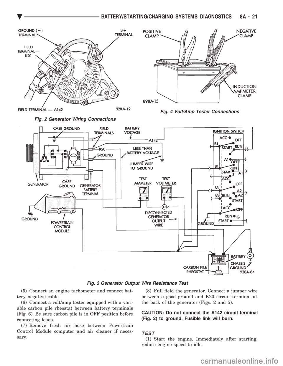
sary. (8) Full field the generator. Connect a jumper wire
between a good ground and K20 circuit terminal at
the back of the generator (Figs. 2 and 5).
CAUTION: Do not connect the A142 circuit terminal
(Fig. 2) to ground. Fusible link will burn.
TEST
(1) Start the engine. Immediately after starting,
reduce engine speed to idle.
Fig. 2 Generator Wiring Connections
Fig. 3 Generator Output Wire Resistance Test
Fig. 4 Volt/Amp Tester Connections
Ä BATTERY/STARTING/CHARGING SYSTEMS DIAGNOSTICS 8A - 21
Page 394 of 2438

(2) Adjust the carbon pile and engine speed in
steps until an engine speed of 1250 rpm, and a volt-
meter reading of 15 volts is obtained.
CAUTION: Do not allow the battery voltage to ex-
ceed 16 volts. (3) The generator amperage must meet the output
requirements for the particular generator being
tested. Refer to Generator Specifications for genera-
tor identification and amperage outputs.
RESULTS
(1) If amperage reading is less than specified, and
generator output wire resistance is not found exces-
sive from the previous tests, generator should be re-
placed. Refer to Group 8B, Battery/Starter/Generator
Service, Generator Replacement. These generators
are not intended to be disassembled for service. It
must be replaced as an assembly. (2) After current output test is completed, reduce
engine speed, turn off carbon pile, and turn off igni-
tion switch. (3) Disconnect battery negative cable.
(4) Remove test ammeter, voltmeter, tachometer
and carbon pile. (5) Remove jumper wire between K20 circuit ter-
minal and ground. (6) Connect output wire to B+ terminal.
(7) Connect negative battery cable.
(8) Connect fresh air hose between powertrain con-
trol module and air cleaner if removed.
Fig. 5 Generator Current Output Test
Fig. 6 Volt/Amp Tester Connections
8A - 22 BATTERY/STARTING/CHARGING SYSTEMS DIAGNOSTICS Ä
Page 445 of 2438
When testing secondary cables for punctures and
cracks with an oscilloscope follow the equipment
manufacturers instructions. If an oscilloscope is not available, secondary cables
can be tested as follows:
CAUTION: Do not leave any one spark plug cable
disconnected any longer than necessary during test-
ing. Excessive heat could damage the catalytic con-
verter. Total test time must not exceed ten minutes.
(a) With the engine not running, connect one end
of a test probe to a good ground. Use a probe made of
insulated wire with insulated alligator clips on each
end. (b) With engine running, move test probe along
entire length of all cables (approximately 0 to 1/8
inch gap). If punctures or cracks are present there
will be a noticeable spark jump from the faulty area
to the probe. Check the coil cable the same way.
Replace cracked, leaking or faulty cables.
When replacing cables, install the new high
tension cable and nipple assembly over cap or
coil tower. When entering the terminal into the
tower, push lightly, then pinch the large diam-
eter of nipple to release air trapped between the
nipple and tower. Continue pushing on the cable
and nipple until cables are properly seated in the
cap towers. A snap should be heard as terminal
goes into place. Use the same procedure to install cable in coil tower.
Wipe the spark plug insulator clean before reinstalling
cable and cover. Use the following procedure when removing the high
tension cable from the spark plug. First, remove the
cable from the retaining bracket. Then grasp the ter-
minal as close as possible to the spark plug. Rotate the
cover and pull the cable straight back. Pulling on the
cable itself will damage the conductor and termi-
nal connection. Do not use pliers and do not pull
the cable at an angle. Doing so will damage the
insulation, cable terminal or the spark plug in-
sulator. Wipe spark plug insulator clean before
reinstalling cable and cover. Resistance type cable is identified by the words
Electronic Suppression printed on the cable jacket.
Use an ohmmeter to check resistance type cable for
open circuits, loose terminals or high resistance as
follows: (a) Remove cable from spark plug.
(b) Lift distributor cap from distributor with
cables intact. Do not remove cables from cap. The
cables must be removed from the spark plugs. (c) Connect the ohmmeter between spark plug end
terminal and the corresponding electrode inside the
cap, make sure ohmmeter probes are in good contact.
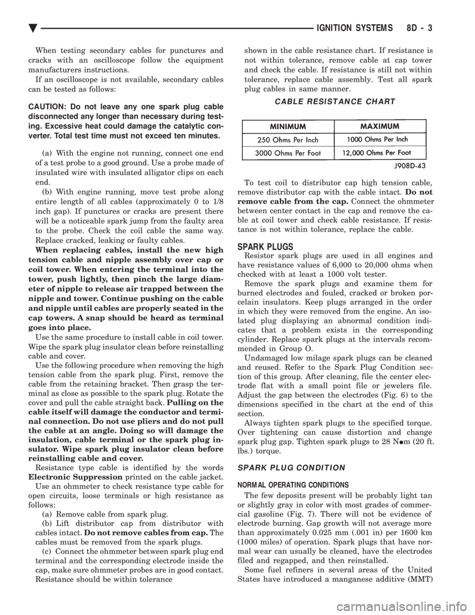
Resistance should be within tolerance shown in the cable resistance chart. If resistance is
not within tolerance, remove cable at cap tower
and check the cable. If resistance is still not within
tolerance, replace cable assembly. Test all spark
plug cables in same manner.
To test coil to distributor cap high tension cable,
remove distributor cap with the cable intact. Do not
remove cable from the cap. Connect the ohmmeter
between center contact in the cap and remove the ca-
ble at coil tower and check cable resistance. If resis-
tance is not within tolerance, replace the cable.
SPARK PLUGS
Resistor spark plugs are used in all engines and
have resistance values of 6,000 to 20,000 ohms when
checked with at least a 1000 volt tester. Remove the spark plugs and examine them for
burned electrodes and fouled, cracked or broken por-
celain insulators. Keep plugs arranged in the order
in which they were removed from the engine. An iso-
lated plug displaying an abnormal condition indi-
cates that a problem exists in the corresponding
cylinder. Replace spark plugs at the intervals recom-
mended in Group O. Undamaged low milage spark plugs can be cleaned
and reused. Refer to the Spark Plug Condition sec-
tion of this group. After cleaning, file the center elec-
trode flat with a small point file or jewelers file.
Adjust the gap between the electrodes (Fig. 6) to the
dimensions specified in the chart at the end of this
section. Always tighten spark plugs to the specified torque.
Over tightening can cause distortion and change
spark plug gap. Tighten spark plugs to 28 N Im (20 ft.
lbs.) torque.
SPARK PLUG CONDITION
NORMAL OPERATING CONDITIONS
The few deposits present will be probably light tan
or slightly gray in color with most grades of commer-
cial gasoline (Fig. 7). There will not be evidence of
electrode burning. Gap growth will not average more
than approximately 0.025 mm (.001 in) per 1600 km
(1000 miles) of operation. Spark plugs that have nor-
mal wear can usually be cleaned, have the electrodes
filed and regapped, and then reinstalled. Some fuel refiners in several areas of the United
States have introduced a manganese additive (MMT)
CABLE RESISTANCE CHART
Ä IGNITION SYSTEMS 8D - 3
Page 454 of 2438
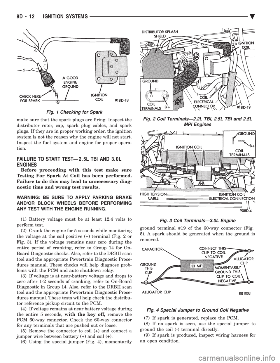
make sure that the spark plugs are firing. Inspect the
distributor rotor, cap, spark plug cables, and spark
plugs. If they are in proper working order, the ignition
system is not the reason why the engine will not start.
Inspect the fuel system and engine for proper opera-
tion.
FAILURE TO START TESTÐ2.5L TBI AND 3.0L
ENGINES
Before proceeding with this test make sure
Testing For Spark At Coil has been performed.
Failure to do this may lead to unnecessary diag-
nostic time and wrong test results.
WARNING: BE SURE TO APPLY PARKING BRAKE
AND/OR BLOCK WHEELS BEFORE PERFORMING
ANY TEST WITH THE ENGINE RUNNING.
(1) Battery voltage must be at least 12.4 volts to
perform test. (2) Crank the engine for 5 seconds while monitoring
the voltage at the coil positive (+) terminal (Fig. 2 or
Fig. 3). If the voltage remains near zero during the
entire period of cranking, refer to Group 14 for On-
Board Diagnostic checks. Also, refer to the DRBII scan
tool and the appropriate Powertrain Diagnostic Proce-
dures manual. These checks will help diagnose prob-
lems with the PCM and auto shutdown relay. (3) If voltage is at near-battery voltage and drops to
zero after 1-2 seconds of cranking, refer to On-Board
Diagnostic in Group 14. Also, refer to the DRBII scan
tool and the appropriate Powertrain Diagnostic Proce-
dures manual. These tests will help check the distribu-
tor reference pickup circuit to the PCM. (4) If voltage remains at near battery voltage during
the entire 5 seconds, with the key off,remove the
PCM 60-way connector. Check the 60-way connector
for any terminals that are pushed out or loose. (5) Remove the connector to coil (+) and connect a
jumper wire between battery (+) and coil (+). (6) Using the special jumper (Fig. 4), momentarily ground terminal #19 of the 60-way connector (Fig.
5). A spark should be generated when the ground is
removed.
(7) If spark is generated, replace the PCM.
(8) If no spark is seen, use the special jumper to
ground the coil (-) terminal directly. (9) If spark is produced, inspect wiring harness for
an open condition.
Fig. 2 Coil TerminalsÐ2.2L TBI, 2.5L TBI and 2.5L MPI Engines
Fig. 3 Coil TerminalsÐ3.0L Engine
Fig. 4 Special Jumper to Ground Coil Negative
Fig. 1 Checking for Spark
8D - 12 IGNITION SYSTEMS Ä