1993 CHEVROLET PLYMOUTH ACCLAIM jump cable
[x] Cancel search: jump cablePage 1715 of 2438
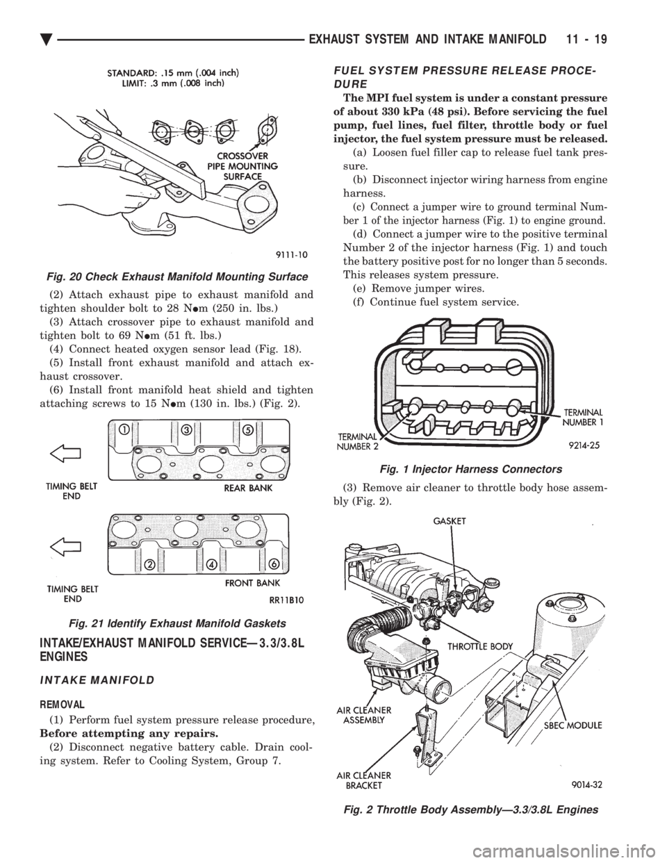
(2) Attach exhaust pipe to exhaust manifold and
tighten shoulder bolt to 28 N Im (250 in. lbs.)
(3) Attach crossover pipe to exhaust manifold and
tighten bolt to 69 N Im (51 ft. lbs.)
(4) Connect heated oxygen sensor lead (Fig. 18).
(5) Install front exhaust manifold and attach ex-
haust crossover. (6) Install front manifold heat shield and tighten
attaching screws to 15 N Im (130 in. lbs.) (Fig. 2).
INTAKE/EXHAUST MANIFOLD SERVICEÐ3.3/3.8L
ENGINES
INTAKE MANIFOLD
REMOVAL
(1) Perform fuel system pressure release procedure,
Before attempting any repairs. (2) Disconnect negative battery cable. Drain cool-
ing system. Refer to Cooling System, Group 7.
FUEL SYSTEM PRESSURE RELEASE PROCE- DURE
The MPI fuel system is under a constant pressure
of about 330 kPa (48 psi). Before servicing the fuel
pump, fuel lines, fuel filter, throttle body or fuel
injector, the fuel system pressure must be released.
(a) Loosen fuel filler cap to release fuel tank pres-
sure. (b) Disconnect injector wiring harness from engine
harness.
(c) Connect a jumper wire to ground terminal Num-
ber 1 of the injector harness (Fig. 1) to engine ground.
(d) Connect a jumper wire to the positive terminal
Number 2 of the injector harness (Fig. 1) and touch
the battery positive post for no longer than 5 seconds.
This releases system pressure. (e) Remove jumper wires.
(f) Continue fuel system service.
(3) Remove air cleaner to throttle body hose assem-
bly (Fig. 2).
Fig. 20 Check Exhaust Manifold Mounting Surface
Fig. 21 Identify Exhaust Manifold Gaskets
Fig. 1 Injector Harness Connectors
Fig. 2 Throttle Body AssemblyÐ3.3/3.8L Engines
Ä EXHAUST SYSTEM AND INTAKE MANIFOLD 11 - 19
Page 1716 of 2438
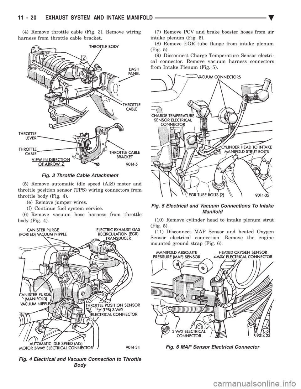
(4) Remove throttle cable (Fig. 3). Remove wiring
harness from throttle cable bracket.
(5) Remove automatic idle speed (AIS) motor and
throttle position sensor (TPS) wiring connectors from
throttle body (Fig. 4). (e) Remove jumper wires.
(f) Continue fuel system service.
(6) Remove vacuum hose harness from throttle
body (Fig. 4). (7) Remove PCV and brake booster hoses from air
intake plenum (Fig. 5). (8) Remove EGR tube flange from intake plenum
(Fig. 5). (9) Disconnect Charge Temperature Sensor electri-
cal connector. Remove vacuum harness connectors
from Intake Plenum (Fig. 5).
(10) Remove cylinder head to intake plenum strut
(Fig. 5). (11) Disconnect MAP Sensor and heated Oxygen
Sensor electrical connection. Remove the engine
mounted ground strap (Fig. 6).
Fig. 3 Throttle Cable Attachment
Fig. 4 Electrical and Vacuum Connection to Throttle Body
Fig. 5 Electrical and Vacuum Connections To IntakeManifold
Fig. 6 MAP Sensor Electrical Connector
11 - 20 EXHAUST SYSTEM AND INTAKE MANIFOLD Ä
Page 1755 of 2438
WARNING: FUEL FILLER TUBE CAPS DESIGNED
FOR GASOLINE ONLY VEHICLES CANNOT BE
USED ON FLEXIBLE FUEL AA-BODY VEHICLES.
WHEN SERVICING THE FUEL SYSTEM OF A FLEX-
IBLE FUEL VEHICLE, ONLY USE ORIGINAL EQUIP-
MENT OR EQUIVALENT REPLACEMENT
COMPONENTS.
FUEL SYSTEM PRESSURE RELEASE
PROCEDUREÐEXCEPT 2.2L/2.5L TBI AND 3.0L
WARNING: RELEASE FUEL SYSTEM PRESSURE
BEFORE SERVICING FUEL SYSTEM COMPONENTS.
WHEN SERVICING FLEXIBLE FUEL VEHICLES,
WEAR METHANOL RESISTANT GLOVES AND EYE
PROTECTION AND AVOID BREATHING FUMES. DO
NOT ALLOW METHANOL/GASOLINE MIXTURES TO
CONTACT SKIN. SERVICE VEHICLES IN WELL VEN-
TILATED AREAS AND AVOID IGNITION SOURCES.
NEVER SMOKE WHILE SERVICING THE VEHICLE.
(1) Disconnect negative cable from battery.
(2) Remove fuel filler cap.
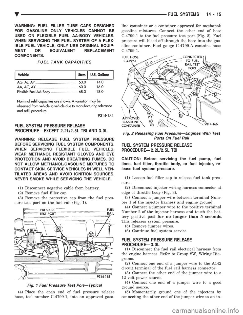
(3) Remove the protective cap from the fuel pres-
sure test port on the fuel rail (Fig. 1).
(4) Place the open end of fuel pressure release
hose, tool number C-4799-1, into an approved gaso- line container or a container approved for methanol/
gasoline mixtures. Connect the other end of hose
C-4799-1 to the fuel pressure test port (Fig. 2). Fuel
pressure will bleed off through the hose into the gas-
oline container. Fuel gauge C-4799-A contains hose
C-4799-1.
FUEL SYSTEM PRESSURE RELEASE
PROCEDUREÐ2.2L/2.5L TBI
CAUTION: Before servicing the fuel pump, fuel
lines, fuel filter, throttle body, or fuel injector, re-
lease fuel system pressure.
(1) Loosen fuel filler cap to release fuel tank pres-
sure. (2) Disconnect injector wiring harness connector at
edge of throttle body (Fig. 3). (3) Connect a jumper wire between terminal Num-
ber 1 of the injector harness and engine ground. (4) Connect a jumper wire to the positive terminal
Number 2 of the injector harness and touch the bat-
tery positive post for no longer than 5 seconds .
This releases system pressure. (5) Remove jumper wires.
(6) Continue fuel system service.
FUEL SYSTEM PRESSURE RELEASE
PROCEDUREÐ3.0L
(1) Disconnect the fuel rail electrical harness from
the engine harness. Refer to Group 8W, Wiring Dia-
grams. (2) Connect one end of a jumper wire to the A142
circuit terminal of the fuel rail harness connector. (3) Connect the other end of the jumper wire to a
12 volt power source. (4) Connect one end of a jumper wire to a good
ground source. (5) Momentarily ground one of the injectors by
connecting the other end of the jumper wire to an in-
FUEL TANK CAPACITIES
Fig. 1 Fuel Pressure Test PortÐTypical
Fig. 2 Releasing Fuel PressureÐEngines With Test Ports On Fuel Rail
Ä FUEL SYSTEMS 14 - 15
Page 1788 of 2438
2.2L/2.5L SINGLE POINT FUEL INJECTIONÐSERVICE PROCEDURES INDEX
page page
Canister Purge Solenoid ................... 53
Electric Exhaust Gas Recirculation Transducer (EET) Service ............................... 53
Fuel Fitting ............................. 50
Fuel Injector ............................ 51
Fuel Lines and Hoses ..................... 48
Fuel Pressure Regulator ................... 51 Fuel System Pressure Release Procedure
...... 48
Heated Oxygen Sensor (O
2Sensor) .......... 54
Idle Air Control Motor ..................... 53
Manifold Absolute Pressure Sensor ........... 53
PCM Service ............................ 54
Throttle Body ............................ 48
Throttle Position Sensor ................... 52
FUEL LINES AND HOSES
Perform the Fuel System Pressure Relief Procedure
before servicing the fuel system. The procedure must
be done to bleed fuel pressure from the system before
removing clamps or hoses. Use care when removing fuel hoses to prevent dam-
age to hose or hose nipple. Always use new hose
clamps, of the correct type, during reassembly. Tighten
hose clamps to 1 N Im (10 in. lbs.) torque. Do not use
aviation style clamps on this system or hose
damage may result.
FUEL SYSTEM PRESSURE RELEASE PROCEDURE
CAUTION: Before servicing the fuel pump, fuel lines,
fuel filter, throttle body, or fuel injector, release fuel
system pressure.
(1) Loosen fuel filler cap to release fuel tank pres-
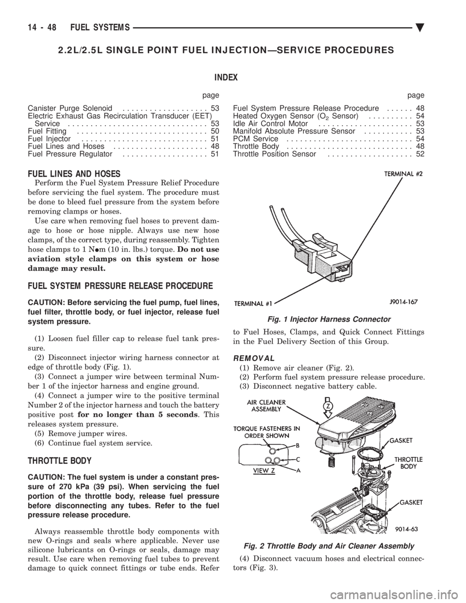
sure. (2) Disconnect injector wiring harness connector at
edge of throttle body (Fig. 1). (3) Connect a jumper wire between terminal Num-
ber 1 of the injector harness and engine ground. (4) Connect a jumper wire to the positive terminal
Number 2 of the injector harness and touch the battery
positive post for no longer than 5 seconds . This
releases system pressure. (5) Remove jumper wires.
(6) Continue fuel system service.
THROTTLE BODY
CAUTION: The fuel system is under a constant pres-
sure of 270 kPa (39 psi). When servicing the fuel
portion of the throttle body, release fuel pressure
before disconnecting any tubes. Refer to the fuel
pressure release procedure.
Always reassemble throttle body components with
new O-rings and seals where applicable. Never use
silicone lubricants on O-rings or seals, damage may
result. Use care when removing fuel tubes to prevent
damage to quick connect fittings or tube ends. Refer to Fuel Hoses, Clamps, and Quick Connect Fittings
in the Fuel Delivery Section of this Group.
REMOVAL
(1) Remove air cleaner (Fig. 2).
(2) Perform fuel system pressure release procedure.
(3) Disconnect negative battery cable.
(4) Disconnect vacuum hoses and electrical connec-
tors (Fig. 3).
Fig. 1 Injector Harness Connector
Fig. 2 Throttle Body and Air Cleaner Assembly
14 - 48 FUEL SYSTEMS Ä
Page 1878 of 2438
3.0L MULTI-PORT FUEL INJECTIONÐSERVICE PROCEDURES INDEX
page page
Idle Air Control Motor .................... 138
Canister Purge Solenoid Service ............ 143
Fuel Injector Rail Assembly ................ 139
Fuel Injectors .......................... 142
Fuel Pressure Regulator Service ............ 141
Fuel System Pressure Release Procedure ..... 138 Heated Oxygen Sensor (O
2Sensor)
......... 144
Manifold Absolute Pressure (MAP) Sensor ..... 143
PCM ................................. 143
Throttle Body ........................... 138
Throttle Body Service .................... 138
Throttle Position Sensor .................. 138
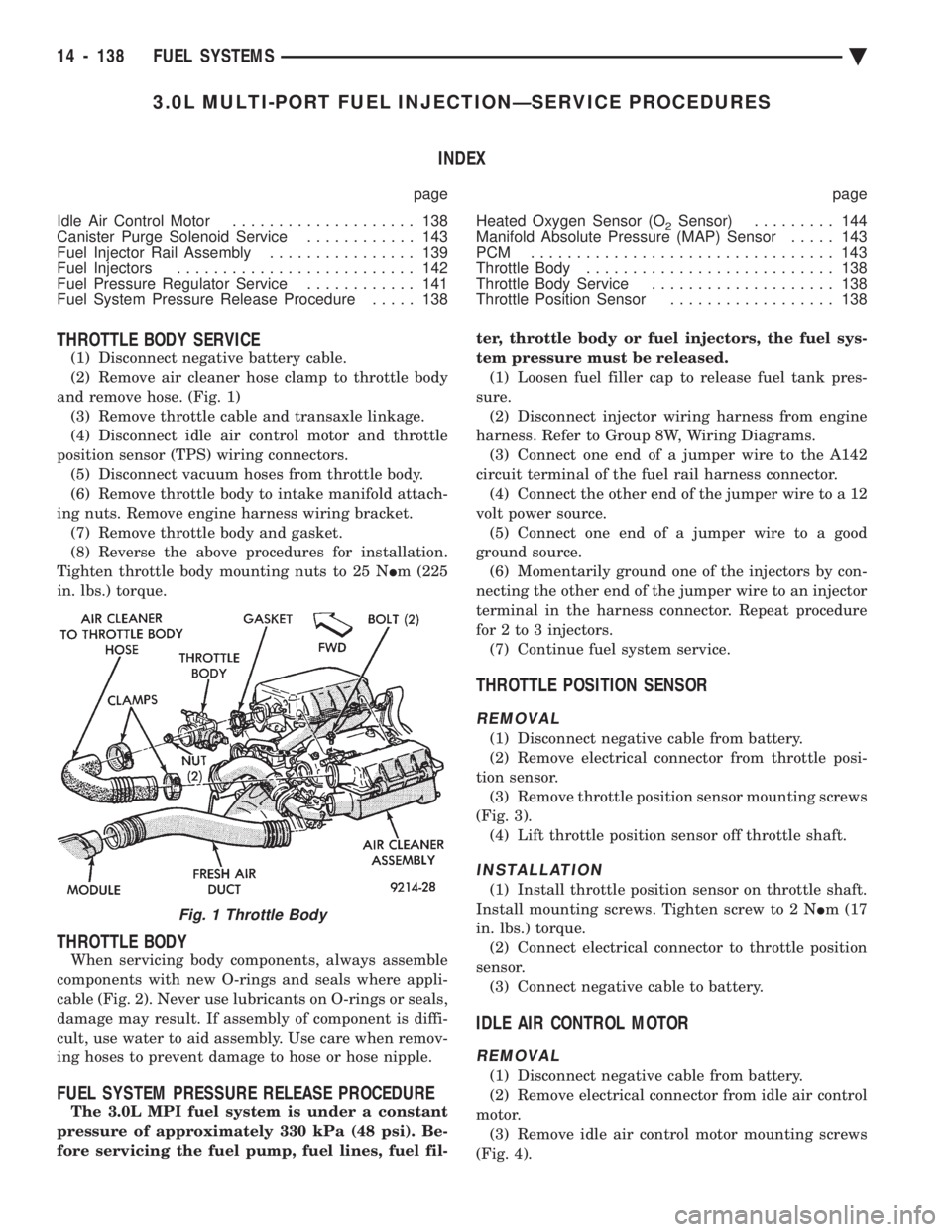
THROTTLE BODY SERVICE
(1) Disconnect negative battery cable.
(2) Remove air cleaner hose clamp to throttle body
and remove hose. (Fig. 1) (3) Remove throttle cable and transaxle linkage.
(4) Disconnect idle air control motor and throttle
position sensor (TPS) wiring connectors. (5) Disconnect vacuum hoses from throttle body.
(6) Remove throttle body to intake manifold attach-
ing nuts. Remove engine harness wiring bracket. (7) Remove throttle body and gasket.
(8) Reverse the above procedures for installation.
Tighten throttle body mounting nuts to 25 N Im (225
in. lbs.) torque.
THROTTLE BODY
When servicing body components, always assemble
components with new O-rings and seals where appli-
cable (Fig. 2). Never use lubricants on O-rings or seals,
damage may result. If assembly of component is diffi-
cult, use water to aid assembly. Use care when remov-
ing hoses to prevent damage to hose or hose nipple.
FUEL SYSTEM PRESSURE RELEASE PROCEDURE
The 3.0L MPI fuel system is under a constant
pressure of approximately 330 kPa (48 psi). Be-
fore servicing the fuel pump, fuel lines, fuel fil- ter, throttle body or fuel injectors, the fuel sys-
tem pressure must be released. (1) Loosen fuel filler cap to release fuel tank pres-
sure. (2) Disconnect injector wiring harness from engine
harness. Refer to Group 8W, Wiring Diagrams. (3) Connect one end of a jumper wire to the A142
circuit terminal of the fuel rail harness connector. (4) Connect the other end of the jumper wire to a 12
volt power source. (5) Connect one end of a jumper wire to a good
ground source. (6) Momentarily ground one of the injectors by con-
necting the other end of the jumper wire to an injector
terminal in the harness connector. Repeat procedure
for 2 to 3 injectors. (7) Continue fuel system service.
THROTTLE POSITION SENSOR
REMOVAL
(1) Disconnect negative cable from battery.
(2) Remove electrical connector from throttle posi-
tion sensor. (3) Remove throttle position sensor mounting screws
(Fig. 3). (4) Lift throttle position sensor off throttle shaft.
INSTALLATION
(1) Install throttle position sensor on throttle shaft.
Install mounting screws. Tighten screw to 2 N Im (17
in. lbs.) torque. (2) Connect electrical connector to throttle position
sensor. (3) Connect negative cable to battery.
IDLE AIR CONTROL MOTOR
REMOVAL
(1) Disconnect negative cable from battery.
(2) Remove electrical connector from idle air control
motor. (3) Remove idle air control motor mounting screws
(Fig. 4).
Fig. 1 Throttle Body
14 - 138 FUEL SYSTEMS Ä
Page 2352 of 2438
WARNING: AVOID RADIATOR/CONDENSER FAN
BLADES WHEN WORKING IN THE RADIATOR
AREA. FAN IS CONTROLLED BY TEMPERATURE
AND CAN START ANY TIME IGNITION IS ON. PER-
SONAL INJURY CAN RESULT.
(1) Disconnect fan control switch wire connector.
(2) Using a suitable jumper wire, jump across ter-
minals in wire connector. (3) Connect a suitable continuity tester across fan
control switch terminals. (4) Start engine and set idle at 1300 rpm. The ra-
diator fan should run constantly. (5) Set the A/C controls to A/C and high blower.
(6) If the high pressure gauge reads below 1102
kPa (160 psi) there should be no continuity across
the switch terminals.
CAUTION: Do not allow engine to overheat when ra-
diator air flow is blocked.
(7) Block radiator air flow with a suitable cover to
increase the high side pressure to at least 1585 kPa
(230 psi). Electrical continuity should be detected
across the fan control switch terminals. (8) Remove cover from front of vehicle to allow
high side pressure to decrease. When pressure drops
below 1102 kPa (160 psi), continuity should cease. If fan control switch is defective, replace it.
REMOVAL AND INSTALLATION
CAUTION: Refrigerant removal is not necessary
when removing the Condenser Fan Control Switch.
However, a small amount of refrigerant will vent
from the switch port. Review the refrigerant han-
dling section of Safety Precautions and Warnings in
the General Information section of this Group.
(1) Disconnect wire connector from condenser fan
control switch. (2) Loosen and quickly rotate the switch counter-
clockwise and separate from the high pressure line
switch port. To install, reverse the preceding operation.
DIFFERENTIAL PRESSURE CUT-OUT SWITCH
DIAGNOSIS
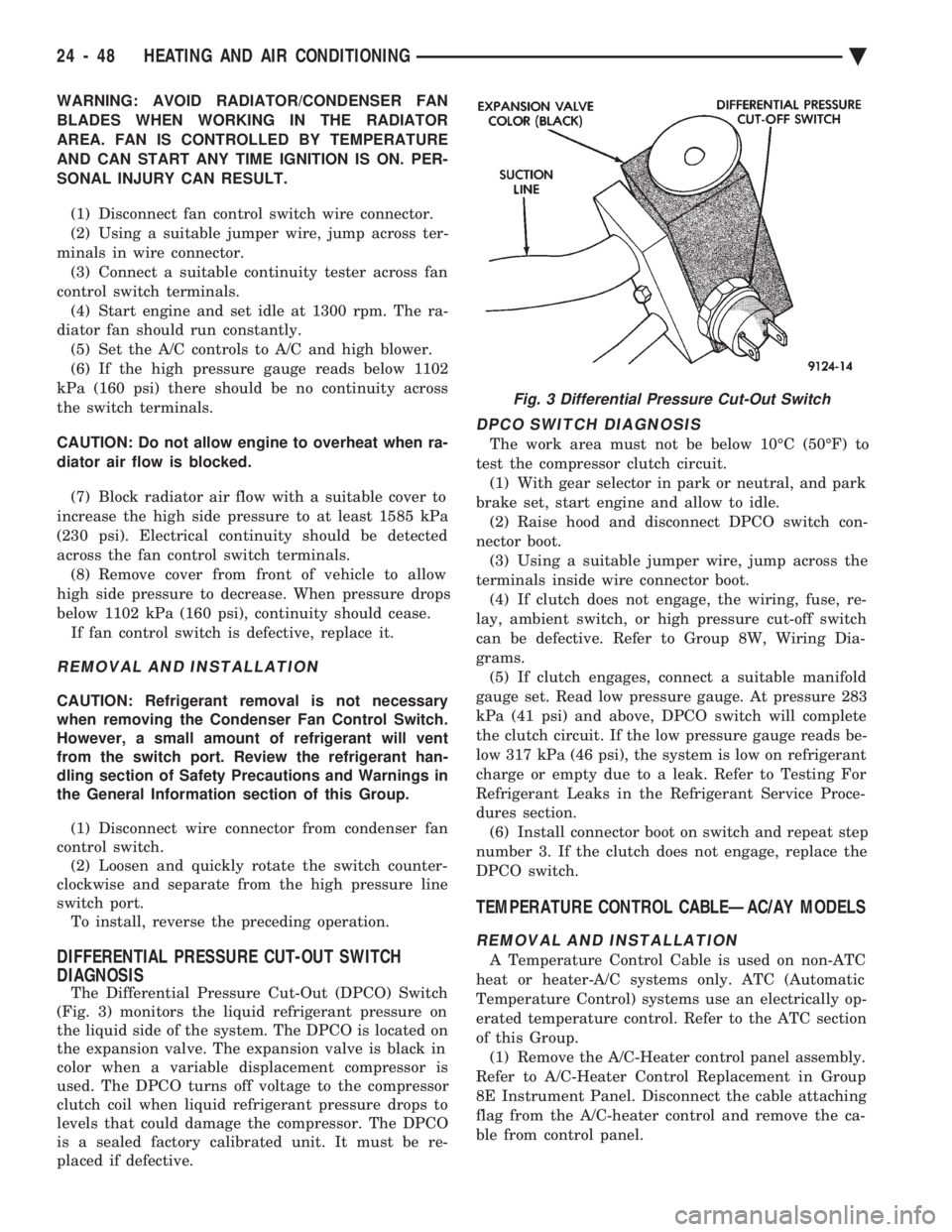
The Differential Pressure Cut-Out (DPCO) Switch
(Fig. 3) monitors the liquid refrigerant pressure on
the liquid side of the system. The DPCO is located on
the expansion valve. The expansion valve is black in
color when a variable displacement compressor is
used. The DPCO turns off voltage to the compressor
clutch coil when liquid refrigerant pressure drops to
levels that could damage the compressor. The DPCO
is a sealed factory calibrated unit. It must be re-
placed if defective.
DPCO SWITCH DIAGNOSIS
The work area must not be below 10ÉC (50ÉF) to
test the compressor clutch circuit. (1) With gear selector in park or neutral, and park
brake set, start engine and allow to idle. (2) Raise hood and disconnect DPCO switch con-
nector boot. (3) Using a suitable jumper wire, jump across the
terminals inside wire connector boot. (4) If clutch does not engage, the wiring, fuse, re-
lay, ambient switch, or high pressure cut-off switch
can be defective. Refer to Group 8W, Wiring Dia-
grams. (5) If clutch engages, connect a suitable manifold
gauge set. Read low pressure gauge. At pressure 283
kPa (41 psi) and above, DPCO switch will complete
the clutch circuit. If the low pressure gauge reads be-
low 317 kPa (46 psi), the system is low on refrigerant
charge or empty due to a leak. Refer to Testing For
Refrigerant Leaks in the Refrigerant Service Proce-
dures section. (6) Install connector boot on switch and repeat step
number 3. If the clutch does not engage, replace the
DPCO switch.
TEMPERATURE CONTROL CABLEÐAC/AY MODELS
REMOVAL AND INSTALLATION
A Temperature Control Cable is used on non-ATC
heat or heater-A/C systems only. ATC (Automatic
Temperature Control) systems use an electrically op-
erated temperature control. Refer to the ATC section
of this Group. (1) Remove the A/C-Heater control panel assembly.
Refer to A/C-Heater Control Replacement in Group
8E Instrument Panel. Disconnect the cable attaching
flag from the A/C-heater control and remove the ca-
ble from control panel.
Fig. 3 Differential Pressure Cut-Out Switch
24 - 48 HEATING AND AIR CONDITIONING Ä