1993 CHEVROLET PLYMOUTH ACCLAIM jump cable
[x] Cancel search: jump cablePage 483 of 2438

(2) With engine running, move test probe along
entire length of all cables (approximately 0 to 1/8
inch gap). If punctures or cracks are present there
will be a noticeable spark jump from the faulty area
to the probe. Cracked, leaking or faulty cables should
be replaced. Use the following procedure when removing the
high tension cable from the spark plug. First, remove
the cable from the retaining bracket. Then grasp the
terminal as close as possible to the spark plug. Ro-
tate the cover (boot) slightly and pull straight back.
Do not use pliers and do not pull the cable at an
angle. Doing so will damage the insulation, cable
terminal or the spark plug insulator. Wipe spark
plug insulator clean before reinstalling cable
and cover. Resistance cables are identified by the words Elec-
tronic Suppression .
Use an ohmmeter to check cables for opens, loose
terminals or high resistance. (a) Remove cable from spark plug.
(b) Remove cable from the coil tower.
(c) Connect the ohmmeter between spark plug
end terminal and the coil end terminal. Resistance
should be within tolerance shown in the cable re-
sistance chart. If resistance is not within tolerance,
replace cable assembly. Test all spark plug cables
in same manner.
SPARK PLUG SERVICE
When replacing the spark plug cables, route the ca-
bles correctly and secure them in the appropriate re-
tainers. Incorrectly routed cables can cause the radio
to reproduce ignition noise. It can also cause cross ig-
nition of the spark plugs or short circuit the cables to
ground.
SPARK PLUG REMOVAL
Always remove cables by grasping at boot, rotating
the boot 1/2 turn, and pulling straight back in a
steady motion. (1) Prior to removing the spark plug spray com-
pressed air around the spark plug hole and the area
around the spark plug. (2) Remove the spark plug using a quality socket
with a rubber or foam insert. (3) Inspect the spark plug condition. Refer to
Spark Plug Condition in this section.
SPARK PLUG GAP ADJUSTMENT
Check the spark plug gap with a gap gauge. If the
gap is not correct, adjust it by bending the ground
electrode (Fig. 6).
SPARK PLUG INSTALLATION
(1) To avoid cross threading, start the spark plug
into the cylinder head by hand. (2) Tighten spark plugs to 28 N Im (20 ft. lbs.)
torque. (3) Install spark plug cables over spark plugs.
IDLE RPM TEST
WARNING: BE SURE TO APPLY PARKING BRAKE
AND/OR BLOCK WHEELS BEFORE PERFORMING
ANY ENGINE RUNNING TESTS.
Engine idle set rpmshould be tested and recorded
as it is when the vehicle is first brought into shop
for testing. This will assist in diagnosing complaints
of engine stalling, creeping and hard shifting on ve-
hicles equipped with automatic transaxle. Refer to the
Throttle Body Minimum Airflow procedures in Group
14.
IGNITION TIMING PROCEDURE
Ignition timing cannot be changed or set on Turbo
III, 3.3L or 3.8L engines. For diagnostic information,
refer to the DRBII scan tool and the appropriate
Powertrain Diagnostics Procedures manual.
CABLE RESISTANCE CHART
Fig. 6 Setting Spark Plug GapÐTypical
Ä IGNITION SYSTEMS 8D - 41
Page 522 of 2438
(b) Refer to sending unit removal Group 14, Fuel.
(c) Connect sending unit wire and jumper wire
as described in the test procedure.
(5) If fuel gauge now checks within specifications,
original sending unit is electrically okay, check fol-
lowing as a possible cause: (a) Ground wire from sending unit to left side
cowl for continuity. (b) Sending unit deformed. Make sure sending
unit float arm moves freely and pick up tube is not
bent upwards creating an interference with bottom
of tank and inspect float. (c) Sending unit improperly installed. Install
properly. (d) Mounting flange on fuel tank for sending
unit deformed. Feel for interference fit of sending
unit to bottom of tank. It is permissible to bend
pick up tube down a little near mounting flange to
gain interference fit. (e) Fuel tank bottom deformed, causing improper
positioning of sending unit pick up tube. Replace or
repair tank and recheck sending unit.
GAUGE CALIBRATION
(1) Remove the gauge.
(2) Check for ignition voltage and ground to the
gauge. (3) With the ignition key in the OFF position, re-
place gauge. Turn the ignition key to the ON posi-
tion. To test oil pressure gauge engine must be
running. When testing oil or temperature gauge the
engine should be at normal operating temperature.
Record the gauge position. (4) Remove gauge and record the resistance be-
tween the sending unit pin and the gauge ground
pin. When checking gauges, it is important to have
the same engine temperature and speed when noting
gauge position. The time between gauge reading and
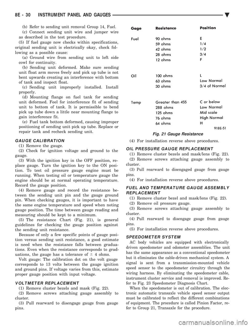
measuring should be kept to a minimum. (5) The resistance Chart (Fig. 21), is general
guidelines for checking the gauge position against
the sending unit resistance. Because of only a few specific points of gauge posi-
tion versus sending unit resistance, a good estimate
is need when the resistance falls between gradua-
tions. Even when the resistance corresponds to grad-
uations, the gauge has a tolerance of 64 ohms.
Volt gauge: The calibration dot on the volt gauge
corresponds to 13 volts between the gauge ignition
and ground pins. If voltage varies from this, estimate
proper gauge position with input voltage.
VOLTMETER REPLACEMENT
(1) Remove cluster bezels and mask (Fig. 22).
(2) Remove screws attaching gauge assembly to
cluster. (3) Pull rearward to disengage gauge from gauge
pins. (4) For installation reverse above procedures.
OIL PRESSURE GAUGE REPLACEMENT
(1) Remove cluster bezels and mask/lens (Fig. 22).
(2) Remove screws attaching gauge assembly to
cluster.
(3) Pull rearward to disengaged gauge from gauge
pins.
(4) For installation reverse above procedures.
FUEL AND TEMPERATURE GAUGE ASSEMBLY REPLACEMENT
(1) Remove cluster bezel and mask/lens (Fig. 22).
(2) Remove oil pressure gauge.
(3) Remove screws attaching gauge assembly to
cluster.
(4) Pull rearward to disengage gauge from gauge
pins.
(5) For installation reverse above procedures.
SPEEDOMETER SYSTEM
AC body vehicles are equipped with electronically
driven speedometer and odometer assemblies. The unit
has the same appearance as a conventional speedometer
but it eliminates the cable-driven mechanical system. A
signal is sent from a transmission-mounted vehicle
speed sensor to the speedometer circuitry through the
wiring harness. By eliminating the speedometer cable,
instrument cluster service and removal is improved. Re-
fer to Fig. 23 Speedometer Diagnosis Chart. When the speedometer is out of calibration. The elec-
tronic automatic transaxle vehicle speed sensor output
must be calibrated to reflect the different combinations
of equipment. The procedure is called Pinion Factor, re-
fer to Group 21, Transaxle for the procedure.
Fig. 21 Gauge Resistance
8E - 30 INSTRUMENT PANEL AND GAUGES Ä
Page 614 of 2438
TESTING PROCEDURES
MULTI-FUNCTION SWITCH TESTS AA, AC, AP, AND AY BODIES
The multi-function switch contains electrical cir-
cuitry for turn signal, cornering lamps (optional),
hazard warning, headlamp beam select, headlamp
optical horn, windshield wiper, pulse wipe, and wind-
shield washer switching. This integrated switch as-
sembly is mounted to the left hand side of the
steering column. Should any function of the switch
fail, the entire switch assembly must be replaced. Re-
fer to Fig. 1 for diagnosis. To test the switch, first disconnect the negative
battery cable, then remove the upper and lower col-
umn covers to gain access to the switch connector.
Remove switch connector. Using an ohmmeter, test
for continuity (no resistance) between the terminals
of the switch as shown in the following continuity
charts (Fig 2 or 3).
DUAL-FUNCTION SWITCH TESTSÐAG AND AJ BODIES
The dual-function switch contains electrical cir-
cuitry for hazard warning switching, and circuitry
and electronics for turn signal cancellation. The
switch assembly is mounted to the left hand side of
the steering column. To test the hazard warning portion of the switch,
first disconnect the negative battery cable, then re-
move the upper and lower steering column covers to
gain access to the switch connector. Remove switch
connector (Fig. 4). Using an ohmmeter, test for con-
tinuity between the terminals of the switch as shown
in the following continuity chart (Fig. 5). To test the cancellation portion of the switch:
(1) Reconnect battery and switch connector (Fig.
5). (2) Connect voltmeter positive lead (+) to pin 8
and negative lead (-) to ground. (3) Place ignition switch to the ON position. Volt-
meter should read battery voltage. If no voltage is
present, check feed wire to pin 8. If battery voltage is
present continue with switch test.
RIGHT CANCELLATION TEST (1) Connect one side of a jumper wire to pin 3 and
the other end of jumper wire to ground. (2) Connect the positive lead (+) of a voltmeter to
pin 5 and the negative lead (-) to ground.
CAUTION: Do not allow pin 5 to become grounded
during test, switch failure will result.
(3) With the ignition switch in the ON position,
push the cancellation pawl down and read the volt-
meter. (4) The voltmeter should show at least 9 volts. (5) If voltage is 0 to 8 volts the cancellation switch
is defective. If voltage is 9 volts or more the cancel-
lation switch is working correctly.
LEFT CANCELLATION TEST
(1) Connect one side of a jumper wire to pin 4 and
the other end of jumper wire to ground. (2) Connect the positive lead (+) of a voltmeter to
pin 5 and the negative lead (-) to ground.
CAUTION: Do not allow pin 5 to become grounded
during test, switch failure will result.
(3) With the ignition switch in the ON position,
push the cancellation pawl up and read the voltme-
ter. (4) The voltmeter should show at least 9 volts.
(5) If voltage is 0 to 8 volts the cancellation switch
is defective. If voltage is 9 volts or more the cancel-
lation switch is working correctly.
REMOTE TURN SIGNAL SWITCH TESTÐAA AND AJ BODIES
The remote turn signal switch is located on the left
side of the instrument panel switch pod. To test, re-
move switch pod assembly from instrument panel.
Using an ohmmeter, test for continuity between the
terminals of the switch as shown in the following
continuity chart (Fig. 6). The white 7 way connector
next to the 14 way connector must be connected
when performing continuity checks.
CANCELLATION SOLENOID TESTÐAG AND AJ BODIES
To test the turn signal cancellation solenoid:
(1) Remove switch pod from instrument panel.
(2) Connect one end of a jumper wire to the posi-
tive terminal of the battery, the other end to pin 6 of
the turn signal switch 14 way connector. (3) Place turn signal switch in the left turn mode.
(4) Take a second jumper wire and connect one end
to a good ground. Momentarily touch the other end of
the jumper wire to pin 11 or 14. The solenoid should
energize, and return the switch to its center OFF po-
sition. (5) Place turn signal switch in the right turn
mode. (6) Repeat step 4. The solenoid should energize,
and return the switch to its center OFF position. (7) If switch does not return to center in either di-
rection, the switch is defective.
MULTI-FUNCTION SWITCHÐAA, AC, AP AND AY
BODIES
REMOVAL
(1) Disconnect negative battery cable.
(2) Tilt column only remove tilt lever.
8J - 2 TURN SIGNALS AND HAZARD WARNING FLASHER Ä
Page 707 of 2438

POWER SEATS
CONTENTS
page page
ADJUSTER ............................. 3
CIRCUIT BREAKER TEST .................. 1
ENTHUSIAST SEAT ....................... 4
GENERAL INFORMATION .................. 1
HARNESS VOLTAGE TEST ................. 1
HORIZONTAL AND VERTICAL TRANSMISSIONS ....................... 3
MEMORY CONTROL MODULE REPLACEMENT ....................... 19
MOTOR ................................ 3
MOTOR TESTS .......................... 1
POWER MEMORY SEAT, RECLINER AND MIRRORS ............................. 5 POWER MEMORY SEAT, RECLINER AND
MIRRORS DIAGNOSIS ................... 9
POWER RECLINER MECHANISM ........... 18
POWER RECLINER MOTOR AND CABLE ..... 17
RECLINER SWITCH REPLACEMENT ......... 19
RECLINER SWITCH TEST ................. 19
SEAT ASSEMBLY ........................ 3
SWITCH REPLACEMENT REMOVAL .......... 5
SWITCH TEST ........................... 5
SWITCH TEST ........................... 3
TEST PROCEDURES ...................... 6
TEST PROCEDURES ...................... 1
GENERAL INFORMATION
Power seats can be adjusted in six different direc-
tions up, down, forward, back, tilt forward, or tilt
rearward. A three armature permanent magnet reversible mo-
tor is coupled through cables to worm gear box assem-
blies located in the seat tracks, providing the various
seat movements. The electrical circuit is protected by a 30 amp circuit
breaker located on the fuse block.
TEST PROCEDURES
Before any testing is attempted the battery should be
carefully charged and all connections and terminals
cleaned and tightened to insure proper continuity and
grounds. With dome lamp on, apply switch in direction of
failure. If dome lamp dims the seat motor is trying to
work indicating mechanical jamming. If dome lamp
does not dim, then proceed with the following electrical
tests.
CIRCUIT BREAKER TEST
Find correct circuit breaker on fuse block. Pull out
slightly but be sure that circuit breaker terminals still
contact terminals in fuse block. Connect ground wire of
voltmeter to a good ground. With probe of voltmeter
positive wire, check both terminals of circuit breaker
for battery voltage. If only one terminal checks at
battery voltage, circuit breaker is defective and must
be replaced. If neither terminal shows battery voltage,
check for open or shorted circuit to circuit breaker.
HARNESS VOLTAGE TEST
The following test will determine whether or not
voltage is continuous through the body harness to the
switch. (1) Remove power seat switch from mounting posi-
tion and disconnect switch from wiring harness. (2) Connect one lead of test light to ground terminal,
black wire (BK) of center section, and touch other test
light lead to red wire (RD) terminal. (3) If test light comes on, harness to switch is good.
If test light does not come on, perform circuit breaker
test.
MOTOR TESTS
AA BODY
(1) Remove switch from mounting position and dis-
connect from harness. (2) To check the center motor, connect a jumper wire
between pin 5 and pin 3 (Fig. 1). Connect a second
jumper wire between pin 7 and pin 4 If motor does not
operate, reverse the jumpers, pin 5 to pin 4 and pin 7 to
pin 3. If motor still does not operate check wiring
between switch connector and motor assembly. If wir-
ing checks good replace motor assembly. (3) To check the front motor, connect a jumper wire
between pin 5 and pin 1 (Fig. 1). Connect a second
jumper wire between pin 7 and pin 8. If motor does not
operate, reverse the jumpers, pin 5 to pin 8 and pin 7 to
pin 1. If motor still does not operate check wiring
between switch connector and motor assembly. If wir-
ing checks good replace motor assembly.
(4) To check the rear motor, connect a covered jumper
wire between pin 5 and pin 6 (Fig. 1). Connect a second
Ä POWER SEATS 8R - 1
Page 709 of 2438
switch connector and motor assembly. If wiring
checks good replace motor assembly.(4) To check the rear motor, connect a jumper wire
between cavity number 3 and cavity number 4. Con-
nect a second jumper wire between cavity number 6
and cavity number 13. If the motor does not operate,
reverse the jumpers, 3 to 13 and 6 to 4. If the motor
still does not operate check the wiring between
switch connector and motor assembly. If wiring
checks good replace motor assembly. (5) If all motors and the seat operate properly, per-
form Switch Test.
SWITCH TEST
To check the switch, remove the switch from its
mounting position. Using an ohmmeter, perform
switch continuity test (Fig. 5, 6 and 7). If there is no
continuity at any one of the switch positions, replace
the switch.
SEAT ASSEMBLY
REMOVAL
(1) Remove plastic covers.
(2) Remove adjuster attaching bolts and nuts from
floor pan. Move adjuster as required for access. (3) Disconnect battery negative cable.
(4) Disconnect wiring harness power lead at car-
pet. (5) Remove seat assembly from vehicle.
INSTALLATION
(1) Position seat assembly in vehicle.
(2) Connect wiring harness.
(3) Install and tighten mounting bolts and nuts to
28 N Im (250 in. lbs.) torque.
(4) Connect battery negative cable and check seat
operation. (5) Install plastic covers.
HORIZONTAL AND VERTICAL TRANSMISSIONS
Transmissions are not removable and no mainte-
nance is required. If transmission fails replace entire
seat adjuster assembly.
ADJUSTER
REMOVAL
(1) Remove seat assembly from vehicle following
procedure outlined under Seat Assembly Removal. (2) Lay seat on its back on some clean surface.
(3) Remove bolts attaching adjuster to seat assem-
bly (Fig. 8 Through 11). (4) Disconnect wiring harness at switch if seat
mounted switch is used. (5) Remove tie straps holding cable housing to seat
for power bench seat adjuster only.
INSTALLATION
(1) Lay seat on its back on a clean surface.
(2) Position adjuster to seat assembly and install
attaching bolts. (3) Connect wiring harness at switch and replace
tie straps where removed. (4) Install seat following procedure outlined under
Seat Assembly Installation.
MOTOR
REMOVAL
Anytime the motor, cable and housing assemblies,
or vertical and horizontal transmission assemblies,
require maintenance, the assemblies must be syn-
chronized to insure easy and proper operation. (1) Remove seat assembly from vehicle following
procedure outlined under Seat Assembly Removal
(Fig. 8 through 11). (2) Lay seat assembly on its back on a clean sur-
face.
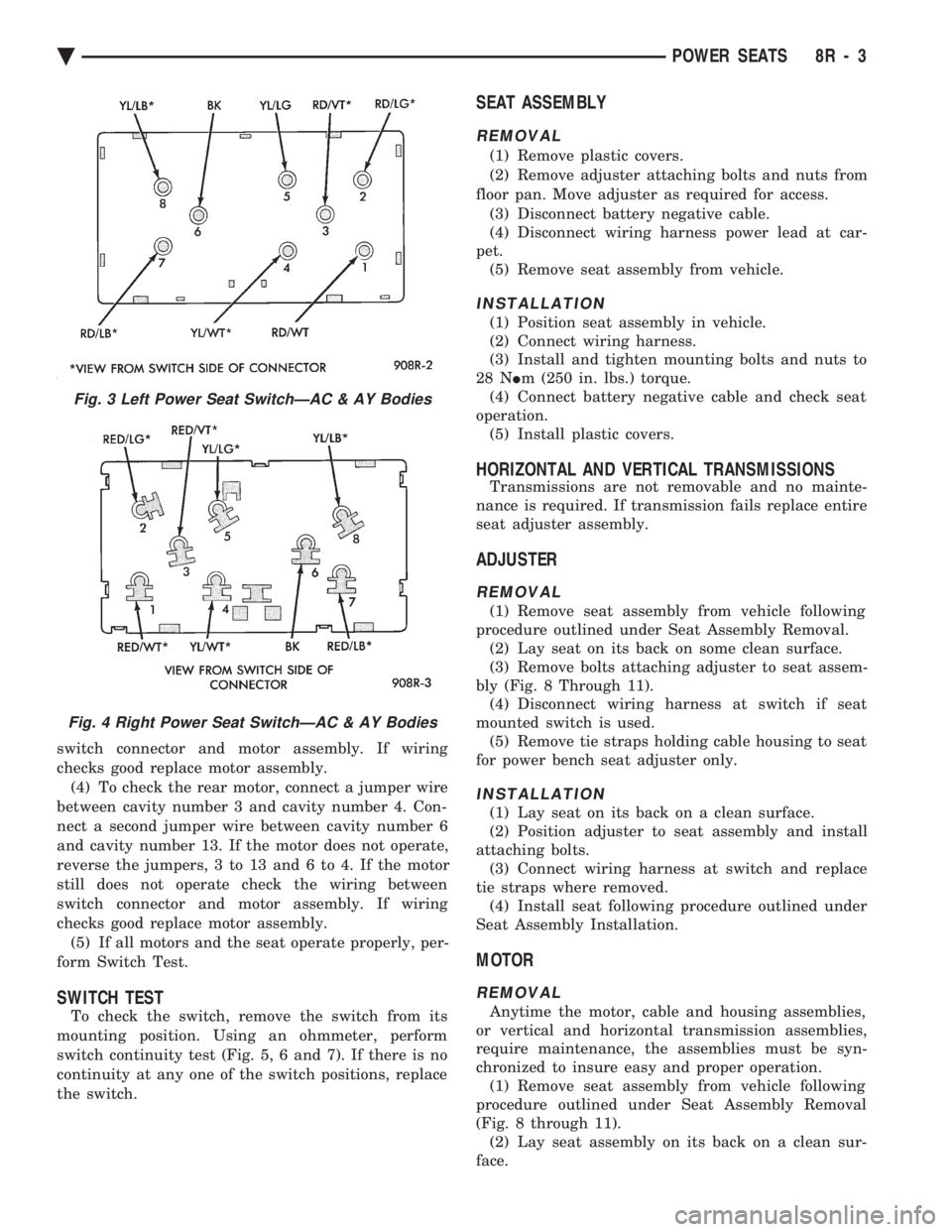
Fig. 3 Left Power Seat SwitchÐAC & AY Bodies
Fig. 4 Right Power Seat SwitchÐAC & AY Bodies
Ä POWER SEATS 8R - 3
Page 1702 of 2438
for diagnostic and service procedures on the air control
valve and temperature sensor located in the air
cleaner.
INTAKE AND EXHAUST MANIFOLDS SERVICEÐTBI
ENGINE
Intake and exhaust manifolds use a one piece gasket.
Service procedures requiring removal and installation
( of either ) must include both manifolds.
FUEL SYSTEM PRESSURE RELEASE PROCE- DURE
The Fuel System is under a constant pressure
of at least 265 kPa (39 psi). Before servicing the
fuel pump, fuel lines, fuel filter, throttle body or
fuel injector, the fuel system pressure must be
released. (a) Loosen fuel filler cap to release fuel tank pres-
sure. (b) Disconnect injector wiring harness from engine
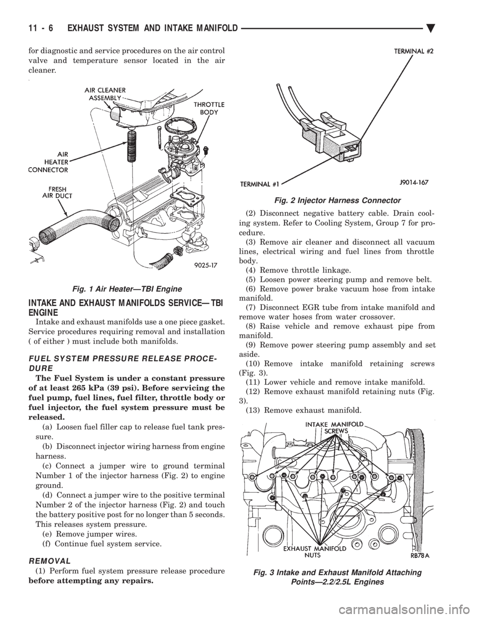
harness. (c) Connect a jumper wire to ground terminal
Number 1 of the injector harness (Fig. 2) to engine
ground. (d) Connect a jumper wire to the positive terminal
Number 2 of the injector harness (Fig. 2) and touch
the battery positive post for no longer than 5 seconds.
This releases system pressure. (e) Remove jumper wires.
(f) Continue fuel system service.
REMOVAL
(1) Perform fuel system pressure release procedure
before attempting any repairs. (2) Disconnect negative battery cable. Drain cool-
ing system. Refer to Cooling System, Group 7 for pro-
cedure. (3) Remove air cleaner and disconnect all vacuum
lines, electrical wiring and fuel lines from throttle
body. (4) Remove throttle linkage.
(5) Loosen power steering pump and remove belt.
(6) Remove power brake vacuum hose from intake
manifold. (7) Disconnect EGR tube from intake manifold and
remove water hoses from water crossover. (8) Raise vehicle and remove exhaust pipe from
manifold. (9) Remove power steering pump assembly and set
aside. (10) Remove intake manifold retaining screws
(Fig. 3). (11) Lower vehicle and remove intake manifold.
(12) Remove exhaust manifold retaining nuts (Fig.
3). (13) Remove exhaust manifold.
Fig. 2 Injector Harness Connector
Fig. 3 Intake and Exhaust Manifold Attaching PointsÐ2.2/2.5L Engines
Fig. 1 Air HeaterÐTBI Engine
11 - 6 EXHAUST SYSTEM AND INTAKE MANIFOLD Ä
Page 1710 of 2438
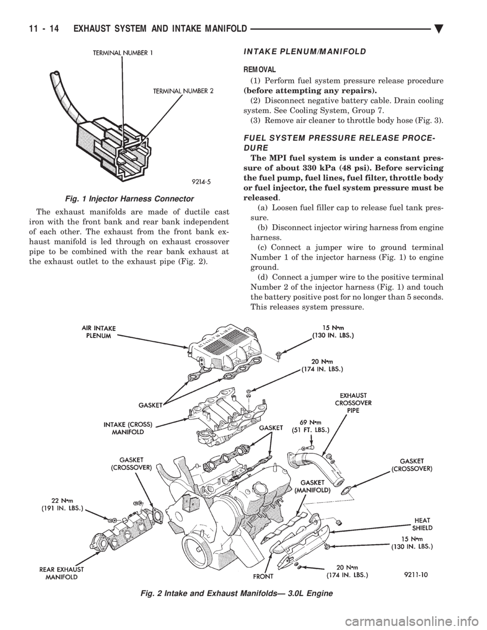
The exhaust manifolds are made of ductile cast
iron with the front bank and rear bank independent
of each other. The exhaust from the front bank ex-
haust manifold is led through on exhaust crossover
pipe to be combined with the rear bank exhaust at
the exhaust outlet to the exhaust pipe (Fig. 2).
INTAKE PLENUM/MANIFOLD
REMOVAL
(1) Perform fuel system pressure release procedure
(before attempting any repairs). (2) Disconnect negative battery cable. Drain cooling
system. See Cooling System, Group 7. (3) Remove air cleaner to throttle body hose (Fig. 3).
FUEL SYSTEM PRESSURE RELEASE PROCE-DURE
The MPI fuel system is under a constant pres-
sure of about 330 kPa (48 psi). Before servicing
the fuel pump, fuel lines, fuel filter, throttle body
or fuel injector, the fuel system pressure must be
released .
(a) Loosen fuel filler cap to release fuel tank pres-
sure. (b) Disconnect injector wiring harness from engine
harness. (c) Connect a jumper wire to ground terminal
Number 1 of the injector harness (Fig. 1) to engine
ground. (d) Connect a jumper wire to the positive terminal
Number 2 of the injector harness (Fig. 1) and touch
the battery positive post for no longer than 5 seconds.
This releases system pressure.
Fig. 1 Injector Harness Connector
Fig. 2 Intake and Exhaust ManifoldsÐ 3.0L Engine
11 - 14 EXHAUST SYSTEM AND INTAKE MANIFOLD Ä
Page 1711 of 2438
(e) Remove jumper wires.
(f) Continue fuel system service.
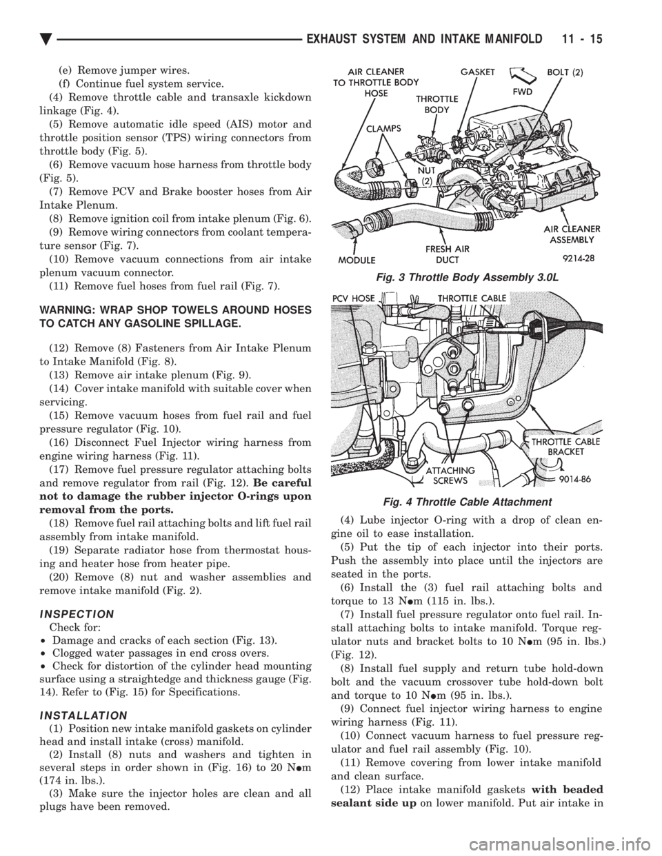
(4) Remove throttle cable and transaxle kickdown
linkage (Fig. 4). (5) Remove automatic idle speed (AIS) motor and
throttle position sensor (TPS) wiring connectors from
throttle body (Fig. 5). (6) Remove vacuum hose harness from throttle body
(Fig. 5). (7) Remove PCV and Brake booster hoses from Air
Intake Plenum. (8) Remove ignition coil from intake plenum (Fig. 6).
(9) Remove wiring connectors from coolant tempera-
ture sensor (Fig. 7). (10) Remove vacuum connections from air intake
plenum vacuum connector. (11) Remove fuel hoses from fuel rail (Fig. 7).
WARNING: WRAP SHOP TOWELS AROUND HOSES
TO CATCH ANY GASOLINE SPILLAGE. (12) Remove (8) Fasteners from Air Intake Plenum
to Intake Manifold (Fig. 8). (13) Remove air intake plenum (Fig. 9).
(14) Cover intake manifold with suitable cover when
servicing. (15) Remove vacuum hoses from fuel rail and fuel
pressure regulator (Fig. 10). (16) Disconnect Fuel Injector wiring harness from
engine wiring harness (Fig. 11). (17) Remove fuel pressure regulator attaching bolts
and remove regulator from rail (Fig. 12). Be careful
not to damage the rubber injector O-rings upon
removal from the ports. (18) Remove fuel rail attaching bolts and lift fuel rail
assembly from intake manifold. (19) Separate radiator hose from thermostat hous-
ing and heater hose from heater pipe. (20) Remove (8) nut and washer assemblies and
remove intake manifold (Fig. 2).
INSPECTION
Check for:
² Damage and cracks of each section (Fig. 13).
² Clogged water passages in end cross overs.
² Check for distortion of the cylinder head mounting
surface using a straightedge and thickness gauge (Fig.
14). Refer to (Fig. 15) for Specifications.
INSTALLATION
(1) Position new intake manifold gaskets on cylinder
head and install intake (cross) manifold. (2) Install (8) nuts and washers and tighten in
several steps in order shown in (Fig. 16) to 20 N Im
(174 in. lbs.). (3) Make sure the injector holes are clean and all
plugs have been removed. (4) Lube injector O-ring with a drop of clean en-
gine oil to ease installation. (5) Put the tip of each injector into their ports.
Push the assembly into place until the injectors are
seated in the ports. (6) Install the (3) fuel rail attaching bolts and
torque to 13 N Im (115 in. lbs.).
(7) Install fuel pressure regulator onto fuel rail. In-
stall attaching bolts to intake manifold. Torque reg-
ulator nuts and bracket bolts to 10 N Im (95 in. lbs.)
(Fig. 12). (8) Install fuel supply and return tube hold-down
bolt and the vacuum crossover tube hold-down bolt
and torque to 10 N Im (95 in. lbs.).
(9) Connect fuel injector wiring harness to engine
wiring harness (Fig. 11). (10) Connect vacuum harness to fuel pressure reg-
ulator and fuel rail assembly (Fig. 10). (11) Remove covering from lower intake manifold
and clean surface. (12) Place intake manifold gaskets with beaded
sealant side up on lower manifold. Put air intake in
Fig. 3 Throttle Body Assembly 3.0L
Fig. 4 Throttle Cable Attachment
Ä EXHAUST SYSTEM AND INTAKE MANIFOLD 11 - 15