1993 CHEVROLET PLYMOUTH ACCLAIM steering wheel
[x] Cancel search: steering wheelPage 301 of 2438

ANTILOCK BRAKES OPERATION AND
PERFORMANCE
The Bendix Antilock 4 Brake System represents
the current state-of-the-art in vehicle brake systems
and offers the driver increased safety and control
during braking. This is accomplished by a sophisti-
cated system of electrical and hydraulic components.
As a result, there are a few performance characteris-
tics that may at first seem different but should be
considered normal. These characteristics are dis-
cussed below. More technical details are discussed
further in this section.
PEDAL FEEL
Since the Bendix Antilock 4 Brake System uses the
vehicle's conventional brake system power booster
and master cylinder. The brake pedal feel during
normal braking is the same as on a conventional
Non ABS equipped vehicle. When the Antilock system becomes activated dur-
ing hard braking due to a wheel lockup tendency.
The brake pedal effort will increase do to the master
cylinder pressure being isolated from the brake sys-
tem. Some brake pedal movement and associated
noises may be felt and heard by the driver. This is
normal operation of the Bendix Antilock 4 Brake
System due to pressurized brake fluid being trans-
ferred to and from the wheel brakes.
ANTILOCK BRAKE SYSTEM OPERATION
During Antilock Brake system operation, brake
pressures are modulated by cycling electric solenoid
valves. The cycling of these valves can be heard as a
series of popping or ticking noises. In addition, the
cycling may be felt as a pulsation in the brake pedal.
If Antilock operation occurs during a hard applica-
tion of the brakes, some pulsation may be felt in the
vehicle body due to fore and aft movement of vehicle
suspension components. Although ABS operation is available at virtually
all vehicle speeds, it will automatically turn off at
speeds below 3 to 5 mph. Wheel lockup may be per-
ceived at the very end of an anti lock stop and is con-
sidered normal.
TIRE NOISE & MARKS
Although the ABS system prevents complete wheel
lock-up, some wheel slip is desired in order to
achieve optimum vehicle braking performance. During brake fluid pressure modulation, as the
brake fluid pressure is increased, wheel slip is al-
lowed to reach up to 30%. This means that wheel
rolling speed is 30% less than that of a free rolling
wheel at a given vehicle speed. This slip may result
in some tire chirping, depending on the road surface.
This sound should not be interpreted as total wheel
lock-up. Complete wheel lock up normally leaves black tire
marks on dry pavement. The Antilock Brake System
will not leave dark black tire marks since the wheel
never reaches a locked condition. Tire marks may
however be noticeable as light patched marks.
VEHICLE PERFORMANCE
Antilock Brakes provide the driver with some
steering control during hard braking, however there
are conditions where the system does not provide any
benefit. In particular, hydroplaning is still possible
when the tires ride on a film of water. This results in
the vehicles tires leaving the road surface rendering
the vehicle virtually uncontrollable. In addition, ex-
treme steering maneuvers at high speed or high
speed cornering beyond the limits of tire adhesion to
the road surface may cause vehicle skidding, inde-
pendent of vehicle braking. For this reason, the ABS
system is termed Antilock instead of Anti-Skid.
SYSTEM SELF-DIAGNOSTICS
The Bendix Antilock 4 Brake System has been de-
signed with the following self diagnostic capabilities. The self diagnostic ABS startup cycle begins when
the ignition switch is turned to the on position. At
this time an electrical check is completed on the ABS
components such as Wheel Speed Sensor Continuity
and System and other Relay continuity. During this
check the Amber Antilock Light is on for approxi-
mately 1-2 seconds. Further Antilock Brake System functional testing
is accomplished once the vehicle is set in motion,
known as drive-off. (1) The solenoid valves and the pump/motor are ac-
tivated briefly to verify function.
Fig. 5 Controller Antilock Brake CAB
Ä ANTILOCK 4 BRAKE SYSTEM 5 - 15
Page 304 of 2438

WHEEL SPEED SENSORS
One Wheel Speed Sensor (WSS), is located at each
wheel (Fig. 5 and 6), and sends a small AC signal to the
control module CAB. This signal is generated by mag-
netic induction. The magnetic induction is created,
when a toothed sensor ring (Tone Wheel) (Fig. 7) passes
a stationary magnetic Wheel Speed Sensor. The CAB
converts the AC signal generated at each wheel into a
digital signal. If a wheel locking tendency is detected,
the CAB will then modulate hydraulic pressure to pre-
vent the wheel or wheels from locking.
The front Wheel Speed Sensor is attached to a boss
in the steering knuckle (Fig. 5). The tone wheel is
part of the outboard constant velocity joint (Fig. 5). The rear Wheel Speed Sensor is mounted to the cal-
iper adapter (Fig. 6) and the rear tone wheel is an
integral part of the rear wheel hub (Fig. 7). The
speed sensor air gap is NOT adjustable.
The four Wheel Speed Sensors are serviced individ-
ually. The front Tone Wheels are serviced as an as-
sembly with the outboard constant velocity joint. The
rear Tone Wheels are serviced as an assembly with
the rear brake hub. Correct Antilock system operation is dependent on
the vehicle's wheel speed signals, that are generated
by the Wheel Speed Sensors. The vehicle's wheels
and tires must all be the same size and type to gen-
erate accurate signals. In addition, the tires must be
inflated to the recommended pressures for optimum
system operation. Variations in wheel and tire size
or significant variations in inflation pressure can
produce inaccurate wheel speed signals.
CONTROLLER ANTILOCK BRAKE CAB
The Antilock Brake Controller is a small micropro-
cessor based device which monitors the brake system
and controls the system while it functions in the An-
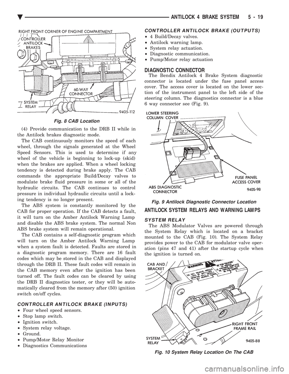
tilock mode. The CAB is mounted on the top of the
right front frame rail and uses a 60-way system con-
nector (Fig. 8). The power source for the CAB is
through the ignition switch in the Run or On posi-
tion. THE CONTROLLER ANTILOCK BRAKE
CAB IS NOT ON THE CCD BUS The primary functions of the CAB are:
(1) Detect wheel locking tendencies.
(2) Control fluid modulation to the brakes while in
Antilock mode. (3) Monitor the system for proper operation.
Fig. 5 Front Wheel Speed Sensor
Fig. 6 Rear Wheel Speed Sensor
Fig. 7 Rear Tone Wheel (Typical)
5 - 18 ANTILOCK 4 BRAKE SYSTEM Ä
Page 305 of 2438

(4) Provide communication to the DRB II while in
the Antilock brakes diagnostic mode. The CAB continuously monitors the speed of each
wheel, through the signals generated at the Wheel
Speed Sensors. This is used to determine if any
wheel of the vehicle is beginning to lock-up (skid)
when the brakes are applied. When a wheel locking
tendency is detected during brake apply. The CAB
commands the appropriate Build/Decay valves to
modulate brake fluid pressure in some or all of the
hydraulic circuits. The CAB continues to control
pressure in individual hydraulic circuits until a lock-
ing tendency is no longer present. The ABS system is constantly monitored by the
CAB for proper operation. If the CAB detects a fault,
it will turn on the Amber Antilock Warning Lamp
and disable the ABS brake system. The normal Non
ABS brake system will remain operational. The CAB contains a self-diagnostic program which
will turn on the Amber Antilock Warning Lamp
when a system fault is detected. Faults are stored in
a diagnostic program memory. There are 16 fault
codes which may be stored in the CAB and displayed
through the DRB II. These fault codes will remain in
the CAB memory even after the ignition has been
turned off. The fault codes can be cleared by using
the DRB II diagnostics tester, or they will be auto-
matically cleared from the memory after (50) ignition
switch on/off cycles.
CONTROLLER ANTILOCK BRAKE (INPUTS)
² Four wheel speed sensors.
² Stop lamp switch.
² Ignition switch.
² System relay voltage.
² Ground.
² Pump/Motor Relay Monitor
² Diagnostics Communications
CONTROLLER ANTILOCK BRAKE (OUTPUTS)
²4 Build/Decay valves.
² Antilock warning lamp.
² System relay actuation.
² Diagnostic communication.
² Pump/Motor relay actuation
DIAGNOSTIC CONNECTOR
The Bendix Antilock 4 Brake System diagnostic
connector is located under the fuse panel access
cover. The access cover is located on the lower sec-
tion of the instrument panel to the left side of the
steering column. The diagnostics connector is a blue
6 way connector see (Fig. 9).
ANTILOCK SYSTEM RELAYS AND WARNING LAMPS
SYSTEM RELAY
The ABS Modulator Valves are powered through
the System Relay which is located on a bracket
mounted to the CAB (Fig. 10). The System Relay
provides power to the CAB for modulator valve oper-
ation (pins 47 and 41) after the startup cycle when
the ignition is turned on.
Fig. 8 CAB Location
Fig. 9 Antilock Diagnostic Connector Location
Fig. 10 System Relay Location On The CAB
Ä ANTILOCK 4 BRAKE SYSTEM 5 - 19
Page 330 of 2438

(4) Carefully, pull sensor assembly grommet from
fender shield. (5) Unplug speed sensor connector from vehicle
wiring harness. (6) Remove the sensor assembly grommets from
the retainer brackets. (7) Remove sensor head screw.
(8) Carefully, remove sensor head from steering
knuckle. If the sensor has seized, due to corrosion,
DO NOT USE PLIERS ON SENSOR HEAD. Use
a hammer and a punch and tap edge of sensor ear,
rocking the sensor side to side until free.
INSTALLATION
(1) Connect the wheel speed sensor connector to
the wiring harness. (2) Push sensor assembly grommet into hole in
fender shield. Install clip and screw. (3) Install the 2 screws that fasten the speed sen-
sor routing tube to the frame rail. (4) Install sensor grommets in brackets on fender
shield and strut damper. (5) Coat the speed sensor with High Temperature
Multi-purpose E.P. Grease before installing into the
steering knuckle. Install screw tighten to 7 N Im (60
in. lbs.)
CAUTION: Proper installation of wheel speed sen-
sor cables is critical to continued system operation.
Be sure that cables are installed in retainers. Fail-
ure to install cables in retainers, as shown in this
section, may result in contact with moving parts
and/or over extension of cables, resulting in an
open circuit.
REAR WHEEL SPEED SENSOR (FIGS. 10 AND 11)
REMOVAL
(1) Raise vehicle and remove wheel and tire as-
sembly. (2) Remove sensor assembly grommet from under-
body and pull harness through hole in underbody. (3) Unplug connector from harness.
(4) Remove sensor assembly grommets from
bracket which is screwed into the body hose bracket,
just forward of trailing arm bushing (batwing brack-
et.) (5) Remove sensor and brake tube assembly clip,
located on the inboard side of trailing arm. (6) Remove sensor wire fastener from rear brake
hose bracket. (7) Remove outboard sensor assembly retainer nut.
This nut also is used to capture the brake tube clip. (8) Remove sensor head screw.
(9) Carefully, remove sensor head from adapter as-
sembly. If the sensor has seized, due to corrosion, DO
NOT USE PLIERS ON SENSOR HEAD. Use a ham-
mer and a punch and tap edge of sensor ear, rocking
the sensor side to side until free.
INSTALLATION Installation is reverse order of removal. Be sure to
coat sensor with High Temperature Multi-purpose
E.P. Grease before installing into adapter assembly.
Tighten screw to 7 N Im (60 in. lbs.) torque.
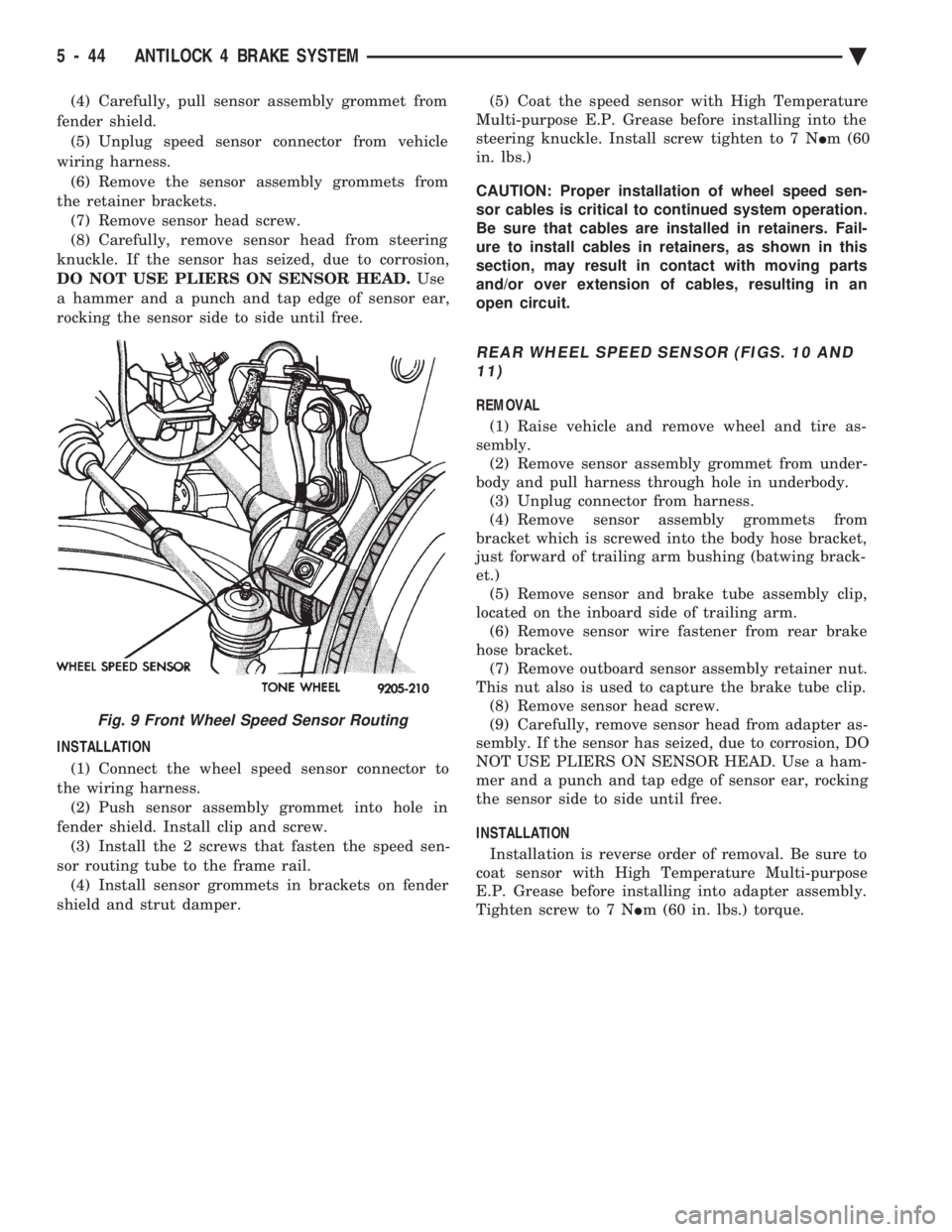
Fig. 9 Front Wheel Speed Sensor Routing
5 - 44 ANTILOCK 4 BRAKE SYSTEM Ä
Page 517 of 2438

off, there should be continuity in the system. Start
the engine. With the engine running, the ohmmeter
should show no continuity. If the above results are
not obtained, replace the switch.
BRAKE SYSTEM WARNING LAMP
The brake warning lamp illuminates when parking
brake is applied with ignition key turned ON. The
same lamp will also illuminate should one of the two
service brake systems fail when brake pedal is ap-
plied. To test system turn ignition key ON, and ap-
ply parking brake. If lamp fails to light, inspect for a
burned out lamp, disconnected socket, a broken or
disconnected wire at switch. The lamp also lights
when the ignition switch is turned to START. To test service brake warning system, raise vehicle
on a hoist and open a wheel cylinder bleeder while a
helper depresses brake pedal and observes warning
light. If lamp fails to light, inspect for a burned out
lamp, disconnected socket, a broken or disconnected
wire at switch. If lamp is not burned out and wire continuity is
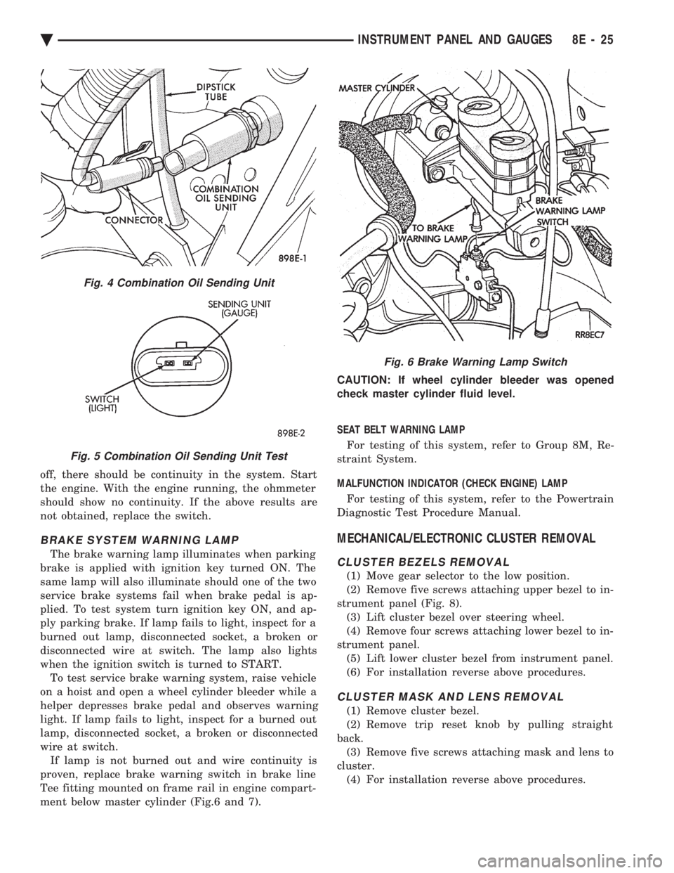
proven, replace brake warning switch in brake line
Tee fitting mounted on frame rail in engine compart-
ment below master cylinder (Fig.6 and 7). CAUTION: If wheel cylinder bleeder was opened
check master cylinder fluid level.
SEAT BELT WARNING LAMP
For testing of this system, refer to Group 8M, Re-
straint System.
MALFUNCTION INDICATOR (CHECK ENGINE) LAMP
For testing of this system, refer to the Powertrain
Diagnostic Test Procedure Manual.
MECHANICAL/ELECTRONIC CLUSTER REMOVAL
CLUSTER BEZELS REMOVAL
(1) Move gear selector to the low position.
(2) Remove five screws attaching upper bezel to in-
strument panel (Fig. 8). (3) Lift cluster bezel over steering wheel.
(4) Remove four screws attaching lower bezel to in-
strument panel. (5) Lift lower cluster bezel from instrument panel.
(6) For installation reverse above procedures.
CLUSTER MASK AND LENS REMOVAL
(1) Remove cluster bezel.
(2) Remove trip reset knob by pulling straight
back. (3) Remove five screws attaching mask and lens to
cluster. (4) For installation reverse above procedures.
Fig. 4 Combination Oil Sending Unit
Fig. 5 Combination Oil Sending Unit Test
Fig. 6 Brake Warning Lamp Switch
Ä INSTRUMENT PANEL AND GAUGES 8E - 25
Page 535 of 2438

ELECTRONIC DIGITAL CLOCK
The electronic digital clock is in the radio. The
clock and radio each use the display panel built into
the radio. A digital readout indicates the time in
hours and minutes whenever the ignition switch is in
the ON or ACC position. When the ignition switch is in the ON or OFF po-
sition, or when the radio frequency is being dis-
played, time keeping is accurately maintained. The procedure for setting the clock varies slightly
with each radio. The correct procedure is described
under the individual radio operating instructions re-
ferred to in the Owner's manual supplied with the
vehicle.
WARNING LAMPS
The AG & AJ Body instrument clusters have warn-
ing lamps or indicators with the electronic cluster for
six different systems. These include low oil pressure,
check gauges, brake system, air bag, seat belt, mal-
function indicator (check engine) lamp.
CLUSTER AND GAUGE SERVICE AND TESTING
CAUTION: Disconnect negative battery cable, in en-
gine compartment, before servicing instrument
panel. When power is required for test purposes,
reconnect battery cable for test only. Disconnect negative battery cable after test and be-
fore continuing service procedures. It is not necessary to remove instrument cluster
from vehicle for gauge replacement. Gauges must be pulled straight out, when remov-
ing or pins may be damaged.
SWITCH POD ASSEMBLY REMOVAL
(1) Disconnect negative battery cable.
(2) Pry up edge of panel vent grille, using a
straight flat edge tool to disengage clips, then re-
move grille (Fig. 4). (3) Remove two screws located under panel vent
grille. (4) Remove two screws underneath switch POD as-
sembly. (5) With tilt steering adjust steering wheel to the
lowest setting. (6) Pull switch module rearward to remove module
and disconnect all wire connections. (7) For Installation reverse above procedures.
Tighten all screws to 2 N Im (20 in. lbs.) torque.
MECHANICAL/ELECTRONIC CLUSTER REMOVAL
CLUSTER MASK AND LENS REMOVAL
(1) Remove switch pod assembly (Fig. 4).
(2) Remove tilt column lever if equipped.
(3) Remove steering column trim cover.
Fig. 4 Switch POD Assembly
Ä INSTRUMENT PANEL AND GAUGES 8E - 43
Page 552 of 2438

CLUSTER BEZEL REPLACEMENT
(1) Remove four screws holding bezel to instru-
ment panel (Fig. 7). (2) Remove bezel over steering wheel. (3) For installation reverse above procedures.
CLUSTER MASK AND LENS
REMOVAL
(1) Remove instrument cluster bezel.
(2) Remove five screws holding mask and lens to
cluster. (3) Remove mask and lens.
(4) For installation reverse above procedures.
CLUSTER ASSEMBLY REPLACEMENT
(1) Disconnect battery to assure no Air Bag Sys-
tem fault codes are stored. (2) Remove cluster bezel (Fig. 7).
(3) Remove the upper steering column cover.
(4) Remove the four screws attaching cluster hous-
ing to the base panel. (5) Pull cluster rearward, reach behind cluster and
disconnect the two wiring harnesses. (6) Remove cluster assembly.
INSTALLATION (1) Connect wiring harnesses.
(2) Position cluster and secure to base panel with
four screws. (3) Install upper and lower steering column cover.
(4) Install cluster bezel.
Fig. 5 Brake System Warning Lamp Diagnosis
Fig. 6 Brake Warning Lamp Switch
8E - 60 INSTRUMENT PANEL AND GAUGES Ä
Page 597 of 2438

HORNS
CONTENTS
page page
GENERAL INFORMATION .................. 1
HORN SWITCH REPLACEMENT ............ 3 TESTING HORN SYSTEM
................. 1
GENERAL INFORMATION
WARNING: ON VEHICLES EQUIPPED WITH AIR
BAG, SEE GROUP 8M, RESTRAINT SYSTEMS FOR
STEERING WHEEL OR COLUMN REMOVAL PROCE-
DURES.
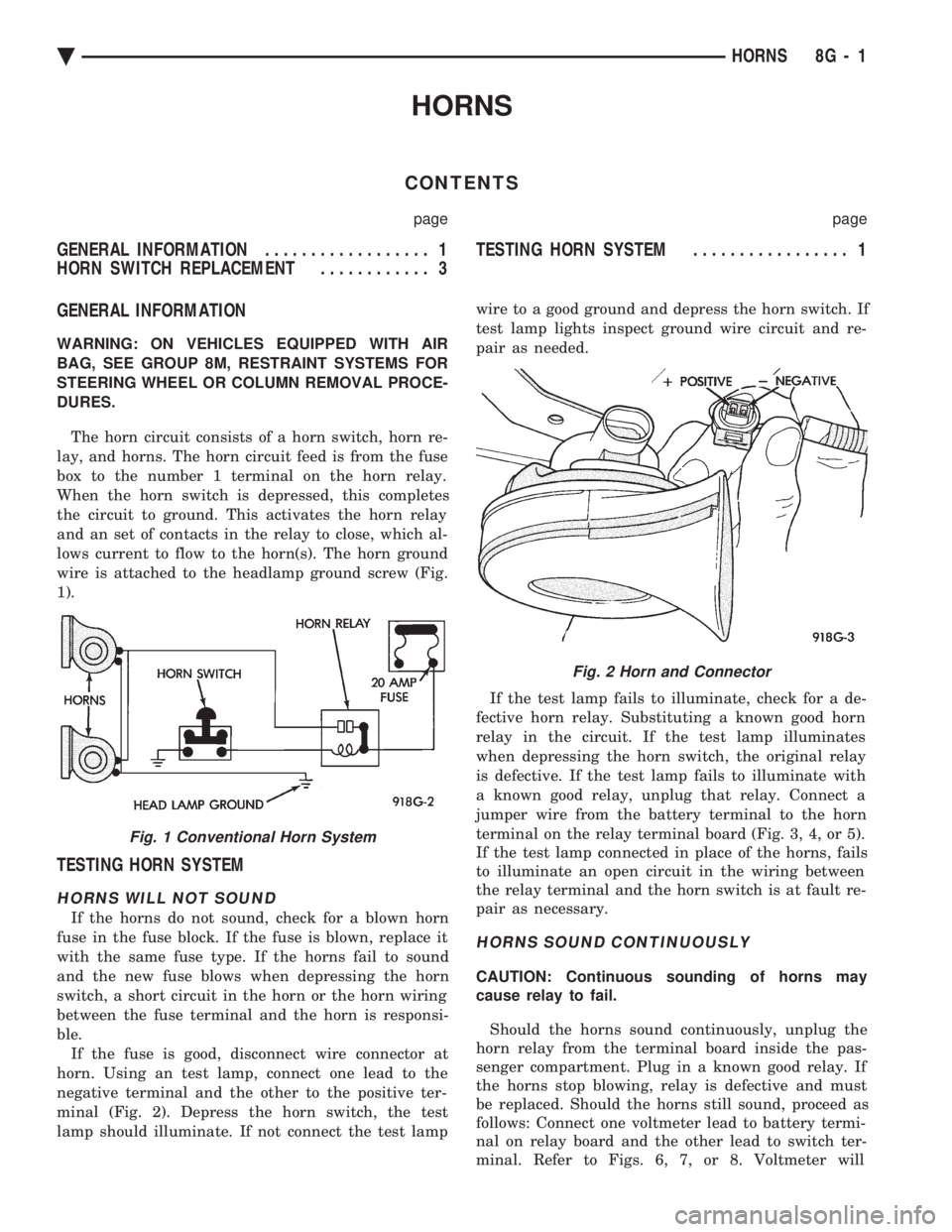
The horn circuit consists of a horn switch, horn re-
lay, and horns. The horn circuit feed is from the fuse
box to the number 1 terminal on the horn relay.
When the horn switch is depressed, this completes
the circuit to ground. This activates the horn relay
and an set of contacts in the relay to close, which al-
lows current to flow to the horn(s). The horn ground
wire is attached to the headlamp ground screw (Fig.
1).
TESTING HORN SYSTEM
HORNS WILL NOT SOUND
If the horns do not sound, check for a blown horn
fuse in the fuse block. If the fuse is blown, replace it
with the same fuse type. If the horns fail to sound
and the new fuse blows when depressing the horn
switch, a short circuit in the horn or the horn wiring
between the fuse terminal and the horn is responsi-
ble. If the fuse is good, disconnect wire connector at
horn. Using an test lamp, connect one lead to the
negative terminal and the other to the positive ter-
minal (Fig. 2). Depress the horn switch, the test
lamp should illuminate. If not connect the test lamp wire to a good ground and depress the horn switch. If
test lamp lights inspect ground wire circuit and re-
pair as needed.
If the test lamp fails to illuminate, check for a de-
fective horn relay. Substituting a known good horn
relay in the circuit. If the test lamp illuminates
when depressing the horn switch, the original relay
is defective. If the test lamp fails to illuminate with
a known good relay, unplug that relay. Connect a
jumper wire from the battery terminal to the horn
terminal on the relay terminal board (Fig. 3, 4, or 5).
If the test lamp connected in place of the horns, fails
to illuminate an open circuit in the wiring between
the relay terminal and the horn switch is at fault re-
pair as necessary.
HORNS SOUND CONTINUOUSLY
CAUTION: Continuous sounding of horns may
cause relay to fail.
Should the horns sound continuously, unplug the
horn relay from the terminal board inside the pas-
senger compartment. Plug in a known good relay. If
the horns stop blowing, relay is defective and must
be replaced. Should the horns still sound, proceed as
follows: Connect one voltmeter lead to battery termi-
nal on relay board and the other lead to switch ter-
minal. Refer to Figs. 6, 7, or 8. Voltmeter will
Fig. 1 Conventional Horn System
Fig. 2 Horn and Connector
Ä HORNS 8G - 1