1993 CHEVROLET PLYMOUTH ACCLAIM steering wheel
[x] Cancel search: steering wheelPage 599 of 2438

Remove steering wheel horn pad and disconnect
wire from horn switch. Repeat the above test and if
the test lamp still illuminates, wire is shorted and
should be repaired. If test lamp does not illuminate,
horn switch is defective and must be replaced.
DIAGNOSIS TESTING
Horn does not sound, horn sounds intermittently,
or horn sounds continuously go to Horn Diagnosis
Chart (Fig. 9).
HORN SWITCH REPLACEMENT
WARNING: BEFORE BEGINNING ANY AIR BAG
SYSTEM REMOVAL OR INSTALLATION PROCE-
DURES, REMOVE AND ISOLATE THE NEGATIVE (-)
BATTERY CABLE (GROUND) FROM THE VEHICLE
BATTERY. THIS IS THE ONLY SURE WAY TO DIS-
ABLE THE AIR BAG SYSTEM. FAILURE TO DO
THIS COULD RESULT IN ACCIDENTAL AIR BAG
DEPLOYMENT AND POSSIBLE PERSONAL INJURY. (1) Disconnect and isolate negative battery cable
in engine compartment. (2) Remove four retaining nuts from back of steer-
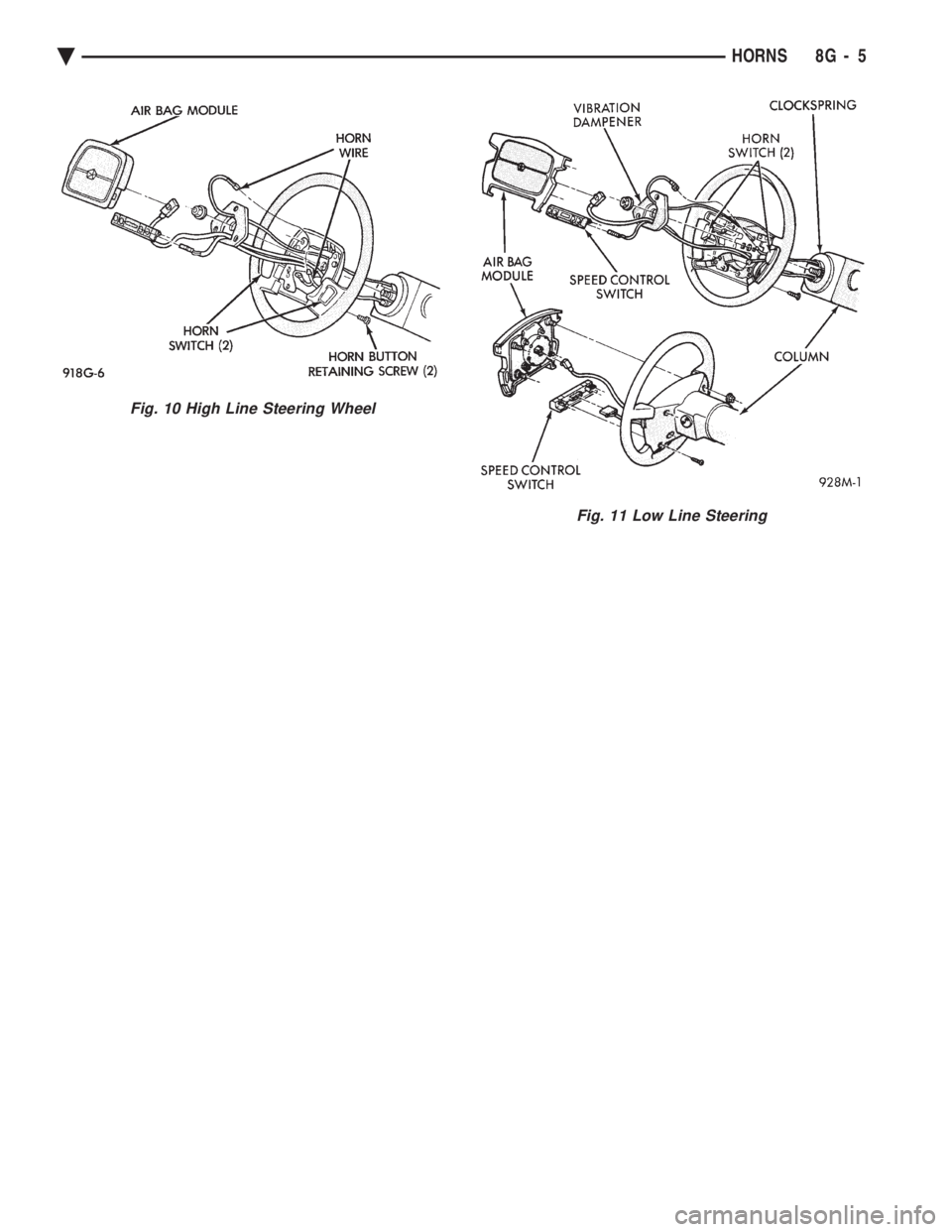
ing wheel. Remove air bag module (Fig. 10 and 11). (a) Disconnect wire from rear of air bag module.
(b) Place air bag module on a clean level surface
with pad facing upward.
(3) Remove horn switch assembly from steering
wheel. (a) On luxury steering wheel (Fig. 10), pry out
two trim cover buttons on back of steering wheel to
access retaining screws for the horn switch. The
sport steering wheel (Fig. 11) the horn screws are
accessible after the Air Bag is removed. (b) Remove two screws and disconnect horn wires
located in the lower portion of steering wheel. Feed
wires through the access ports and remove horn
switch.
(4) For installation reverse the above procedures.
Use caution not to pinch wires.
Fig. 8 Testing Horn for Continuous SoundÐ AP and AA Bodies
Fig. 7 Testing for Short to GroundÐAC and AY Bodies
Ä HORNS 8G - 3
Page 601 of 2438

Fig. 10 High Line Steering Wheel
Fig. 11 Low Line Steering
Ä HORNS 8G - 5
Page 603 of 2438

VEHICLE SPEED CONTROL
CONTENTS
page page
CHECKING FOR FAULT CODE .............. 3
DIAGNOSIS PROCEDURES ................ 2
GENERAL INFORMATION .................. 1
INOPERATIVE SYSTEM ................... 3
POWERTRAIN CONTROL MODULE ELECTRICAL TEST ................................ 5
ROAD TEST ............................ 2
SERVO ELECTRICAL TESTS ............... 4
SERVO UNIT ............................ 9 SERVO VACUUM TEST
................... 9
STOP LAMP VEHICLE SPEED CONTROL SWITCH TEST ......................... 8
VACUUM SUPPLY TEST .................. 9
VEHICLE SPEED CONTROL SWITCH REMOVAL ........................... 10
VEHICLE SPEED CONTROL SWITCH TEST . . . 8
VEHICLE SPEED CONTROL ELECTRICAL TESTS ............................... 3
GENERAL INFORMATION
The vehicle speed control is electronically con-
trolled and vacuum operated. The electronic control
is integrated into the powertrain control module, lo-
cated next to battery. The controls are located on the
steering wheel and consist of the ON/OFF, RESUME/
ACCEL and SET/DECEL buttons (Fig. 1). For iden-
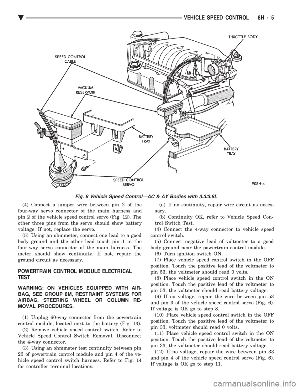
tification and location of the major components (Fig.
2 through 8).
The system is designed to operate at speeds above
35 mph (50 km/h).
WARNING: THE USE OF VEHICLE SPEED CON-
TROL IS NOT RECOMMENDED WHEN DRIVING
CONDITIONS DO NOT PERMIT MAINTAINING A
CONSTANT SPEED, SUCH AS IN HEAVY TRAFFIC
OR ON ROADS THAT ARE WINDING, ICY, SNOW
COVERED, OR SLIPPERY.
TO ACTIVATE: The ON/OFF button to the de-
pressed latched position, ON, the vehicle speed con-
trol function is now ready for use. TO DEACTIVATE:
A soft tap of the brake pedal,
normal brake application or depressing the clutch
pedal while the system is engaged will disengage ve-
hicle speed control without erasing memory. A sud-
den increase in engine rpm may be experienced if the
clutch pedal is depressed while the vehicle speed con-
trol is engaged. Pushing the ON/OFF button to the
unlatched position or turning off the ignition erases
the memory. TO SET SPEED: When the vehicle has reached
the desired speed push the SET/DECEL button to en-
gage system which will then automatically maintain
the desired speed. TO DECELERATE: When vehicle speed control is
engaged, holding the SET/DECEL button depressed
allows the vehicle to coast to a lower speed setting.
Fig. 1 Vehicle Speed Control Switch
Fig. 2 Vehicle Speed ControlÐ2.2L and 2.5L
Ä VEHICLE SPEED CONTROL 8H - 1
Page 606 of 2438

Electronic vehicle speed control may be tested us-
ing two different methods. One involves use of a
DRB II. If this test method is desired, refer to the
Powertrain Diagnostic Test Procedures for charging
and vehicle speed control manual. The other test method uses a volt/ohm meter and is
described in the following tests. If any information is needed concerning wiring, re-
fer to Group 8W, Wiring Diagrams.
CAUTION: When test probing for voltage or conti-
nuity at electrical connectors, care must be taken
not to damage connector, terminals, or seals. If
these components are damaged, intermittent or
complete system failure may occur.
SERVO ELECTRICAL TESTS
WARNING: ON VEHICLES EQUIPPED WITH AIR-
BAG, SEE GROUP 8M, RESTRAINT SYSTEMS FOR
AIRBAG, STEERING WHEEL OR COLUMN RE-
MOVAL PROCEDURES.
(1) Turn ignition switch to the ON position. With
the vehicle speed control switch in the ON position,
set up a voltmeter to read battery voltage and con-
nect the negative lead to a good chassis ground. (2) Disconnect the four-way connector going to the
servo (Fig. 12). Test pin 2 of the main harness four-
way connector for battery voltage. If not OK go to
step 3. If voltage is OK go to step 4. (3) Perform the following tests.(a) Disconnect the six-way connector at the stop
lamp switch and test pin 1 of the main harness for
battery voltage. If voltage is OK perform the stop
lamp switch test. (b) If the stop lamp switch tests OK; repair wire
between the servo and the stop lamp switch. (c) If no voltage at pin 1 at the 6-way stop lamp
connector, remove the vehicle speed control switch
and disconnect the four-way connector. Test pin 1
of main harness for battery voltage. (d) If voltage is OK perform the vehicle speed
control switch test. (e) If vehicle speed control switch is OK, test
continuity across the clockspring. (f) If clockspring OK, repair as required, wire be-
tween stop lamp switch and clockspring. (g) If no voltage at pin 1 of the 4-way vehicle
speed control switch connector.
² Test for battery voltage between the ignition and
the fuse
² If voltage OK, check fuse
² If fuse OK, repair wire between fuse and clock-
spring
Fig. 7 Vehicle Speed ControlÐAC & AY Bodies with 3.0L
8H - 4 VEHICLE SPEED CONTROL Ä
Page 607 of 2438

(4) Connect a jumper wire between pin 2 of the
four-way servo connector of the main harness and
pin 2 of the vehicle speed control servo (Fig. 12). The
other three pins from the servo should show battery
voltage. If not, replace the servo. (5) Using an ohmmeter, connect one lead to a good
body ground and the other lead touch pin 1 in the
four-way servo connector of the main harness. The
meter should show continuity. If not, repair the
ground circuit as necessary.
POWERTRAIN CONTROL MODULE ELECTRICAL
TEST
WARNING: ON VEHICLES EQUIPPED WITH AIR-
BAG, SEE GROUP 8M, RESTRAINT SYSTEMS FOR
AIRBAG, STEERING WHEEL OR COLUMN RE-
MOVAL PROCEDURES.
(1) Unplug 60-way connector from the powertrain
control module, located next to the battery (Fig. 13). (2) Remove vehicle speed control switch. Refer to
Vehicle Speed Control Switch Removal. Disconnect
the 4-way connector. (3) Using an ohmmeter test continuity between pin
23 of powertrain control module and pin 4 of the ve-
hicle speed control switch harness. Refer to Fig. 14
for controller terminal locations. (a) If no continuity, repair wire circuit as neces-
sary. (b) Continuity OK, refer to Vehicle Speed Con-
trol Switch Test.
(4) Connect the 4-way connector to vehicle speed
control switch. (5) Connect negative lead of voltmeter to a good
body ground near the powertrain control module. (6) Turn ignition switch ON.
(7) Place vehicle speed control switch in the OFF
position. Touch the positive lead of the voltmeter to
pin 53, the voltmeter should read 0 volts. (8) Place vehicle speed control switch in the ON
position. Touch the positive lead of the voltmeter to
pin 53, the voltmeter should read battery voltage. (9) If no voltage, repair the wire between pin 53
and pin 3 of the vehicle speed control servo (Fig. 6).
If voltage is OK go to step 8. (10) Place vehicle speed control switch in the OFF
position. Touch the positive lead of the voltmeter to
pin 33, voltmeter should read 0 volts. (11) Place vehicle speed control switch in the ON
position. Touch the positive lead of the voltmeter to
pin 33, the voltmeter should read battery voltage. (12) If no voltage, repair the wire between pin 33
and pin 4 of the vehicle speed control servo (Fig. 6).
If voltage is OK go to step 11.
Fig. 8 Vehicle Speed ControlÐAC & AY Bodies with 3.3/3.8L
Ä VEHICLE SPEED CONTROL 8H - 5
Page 612 of 2438

(4) Disconnect electrical connector and vacuum
hose. (5) Pull cable away from servo to expose retaining
clip and remove clip attaching cable to servo.
INSTALLATION
(1) With throttle in full open position align hole in
vehicle speed control cable sleeve with hole in servo
pin and install retaining clip. (2) Connect vacuum hose to servo.
(3) Connect electrical connector.
(4) Position mounting bracket and install screws
attaching bracket and tighten to 12 N Im (105 in.
lbs.) torque. (5) Insert servo studs through holes in vehicle
speed control cable and mounting bracket. (6) Install nuts, tighten to 7 N Im (60 in. lbs.)
torque.
VEHICLE SPEED CONTROL SWITCH REMOVAL
The vehicle speed control switch is mounted in the
steering wheel and wired through the clock spring
device under the steering wheel hub (Fig.1).
WARNING: IF REMOVAL OF AIR BAG MODULE IS
NECESSARY, REFER TO GROUP 8M, RESTRAINT
SYSTEMS.
REMOVAL
(1) Turn off ignition.
(2) Remove two screws from back side of steering
wheel. (3) Rock switch away from air bag or horn pad
while lifting switch out of steering wheel. (4) Disconnect 4-way electrical connector.
INSTALLATION
(1) Turn off ignition.
(2) Connect 4-way electrical connector from clock
spring to switch. (3) Place switch in steering wheel, sliding the for-
ward edge of switch under air bag or horn pad. Line
up locating pins on switch with holes in steering
wheel frame. (4) Attach switch to wheel with two screws start-
ing with the screw at the left end of the switch.
8H - 10 VEHICLE SPEED CONTROL Ä
Page 613 of 2438

TURN SIGNALS AND HAZARD WARNING FLASHER
CONTENTS
page page
AG AND AJ BODIES ..................... 1
CHIME FUNCTIONÐAC, AG, AJ AND AY .... 1
DUAL-FUNCTION SWITCHÐAG AND AJ BODIES.5
GENERAL INFORMATION .................. 1
HAZARD WARNING SYSTEM .............. 1
MULTI-FUNCTION SWITCHÐAA, AC, AP AND AY BODIES .............................. 2 REMOTE TURN SIGNAL SWITCH REMOVALÐAG
AND AJ BODIES ....................... 5
TESTING PROCEDURES ................... 2
TURN SIGNAL AND HAZARD WARNING FLASHER LOCATION ............................ 6
TURN SIGNAL RELAYSÐAG AND AJ BODIES . 6
GENERAL INFORMATION
WARNING: ON VEHICLES EQUIPPED WITH AIR-
BAG, SEE GROUP 8M, RESTRAINT SYSTEMS FOR
AIRBAG REMOVAL PROCEDURES.
TURN SIGNALSÐAC, AY, AA AND AP BODIES
The turn signals are part of the multi-function switch.
Which contains electrical circuitry for turn signal, cor-
nering lamps, hazard warning, headlamp beam select,
headlamp optical horn, windshield wiper, pulse wipe
and windshield washer switching. The integrated switch
assembly is mounted to the left hand side of the steer-
ing column. When the driver wishes to signal his inten-
tions to change direction of travel, he moves the lever
upward to cause the right signals to flash and down-
ward to cause the left signals to flash. After completion
of a turn the system is deactivated automatically. As
the steering wheel returns to the straight ahead posi-
tion, a canceling cam of two lobes molded to the clock-
spring mechanism comes in contact with the cancel
actuator on the turn signal multi-function switch as-
sembly. Either cam lobe, pushing on the cancel actua-
tor, returns the switch to the off position. If only momentary signaling such as indication of a
lane change is desired, the switch is actuated to a left
or right intermediate detent position. In this position
the signal lamps flash as described above, but the
switch returns to the OFF position as soon as the lever
is released.
When the system is activated, 1 of 2 indicator
lamps mounted in the instrument cluster flashes in
unison with the turn signal lamps, indicating to the
driver that the system is operating.
AG AND AJ BODIES
The turn signals are actuated with lever on the left
side of the instrument panel switch pod. When the
driver wishes to signal his intentions to change di- rection of travel, he moves the lever upward to cause
the right signals to flash and downward to cause the
left signals to flash. After completion of a turn the system is deacti-
vated automatically. The cancellation switch in the
steering column sends a signal to a remote turn sig-
nal switch in the switch pod to cancel the turn signal
function. As the steering wheel returns to the
straight ahead position from a turn, a cancel cam
which is located on the steering wheel contacts a
cancel flipper located on the cancellation switch.
When the flipper is contacted by the cancel cam in
the proper rotational direction, the cancel switch
sends a signal to the remote turn signal switch. If only momentary signaling such as indication of a
lane change is desired, the switch is actuated to a
left or right intermediate detent position. In this po-
sition the signal lamps flash as described above, but
the switch returns to the OFF position as soon as the
lever is released. When the system is activated, 1 of 2 indicator
lamps mounted in the instrument cluster flashes in
unison with the turn signal lamps, indicating to the
driver that the system is operating.
HAZARD WARNING SYSTEM
The hazard warning system is actuated by a push
button located on the top of the steering column be-
tween the steering wheel and the instrument panel.
The hazard switch is identified with a double trian-
gle on top of the button. Push and release the button
to turn the hazard function ON or OFF. The button
will move out from the steering column in the ON
position and will remain in toward the column in the
OFF position.
CHIME FUNCTIONÐAC, AG, AJ AND AY
The chime will sound after the vehicle has traveled
a distance of 0.6 miles at a speed above 15 miles per
hour.
Ä TURN SIGNALS AND HAZARD WARNING FLASHER 8J - 1
Page 621 of 2438

WINDSHIELD WIPER AND WASHER SYSTEMS
CONTENTS
page page
GENERAL WIPER INFORMATION ........... 1
INTERMITTENT WINDSHIELD WIPER MOTOR AND SWITCH SERVICE PROCEDURES .... 12
WINDSHIELD WASHERS ................. 17 WINDSHIELD WIPER BLADE AND ARM SERVICE
PROCEDURES ......................... 1
WINDSHIELD WIPER MOTOR AND LINKAGE ASSEMBLY SERVICE PROCEDURES ....... 3
GENERAL WIPER INFORMATION
WARNING: ON VEHICLES EQUIPPED WITH AIR-
BAG, SEE GROUP 8M, RESTRAINT SYSTEMS FOR
STEERING WHEEL OR COLUMN REMOVAL PROCE-
DURES.
The windshield wipers can be operated with the
windshield wiper switch only when the ignition
switch is in the ACCESSORY or IGNITION position.
A fuse, located in the fuse block, protects the cir-
cuitry of the wiper system and the vehicle. The wiper motor has permanent magnet fields. The speeds are determined by current flow to the appro-
priate set of brushes. The intermittent wipe system, in addition to low
and high speed, has a delay mode. The delay mode
has a range of 2 to 15 seconds. This is accomplished
by a variable resistor in the wiper switch and is con-
trolled electrically by a relay. The wiper system completes the wipe cycle when
the switch is turned OFF. The blades park in the
lowest portion of the wipe pattern.
WINDSHIELD WIPER BLADE AND ARM SERVICE PROCEDURES
WIPER BLADES
Wiper blades, exposed to the weather for a long pe-
riod of time, tend to lose their wiping effectiveness.
Periodic cleaning of the wiper blade is suggested to
remove the accumulation of salt and road film. The
wiper blades, arms, and windshield should be cleaned
with a sponge or cloth and a mild detergent or nona-
brasive cleaner. If the blades continue to streak or
smear, they should be replaced.
WIPER BLADE ELEMENT CHANGE
(1) Turn wiper switch ON, position blades to a con-
venient place by turning the ignition switch ON and
OFF. (2) Lift wiper arm to raise blade off glass.
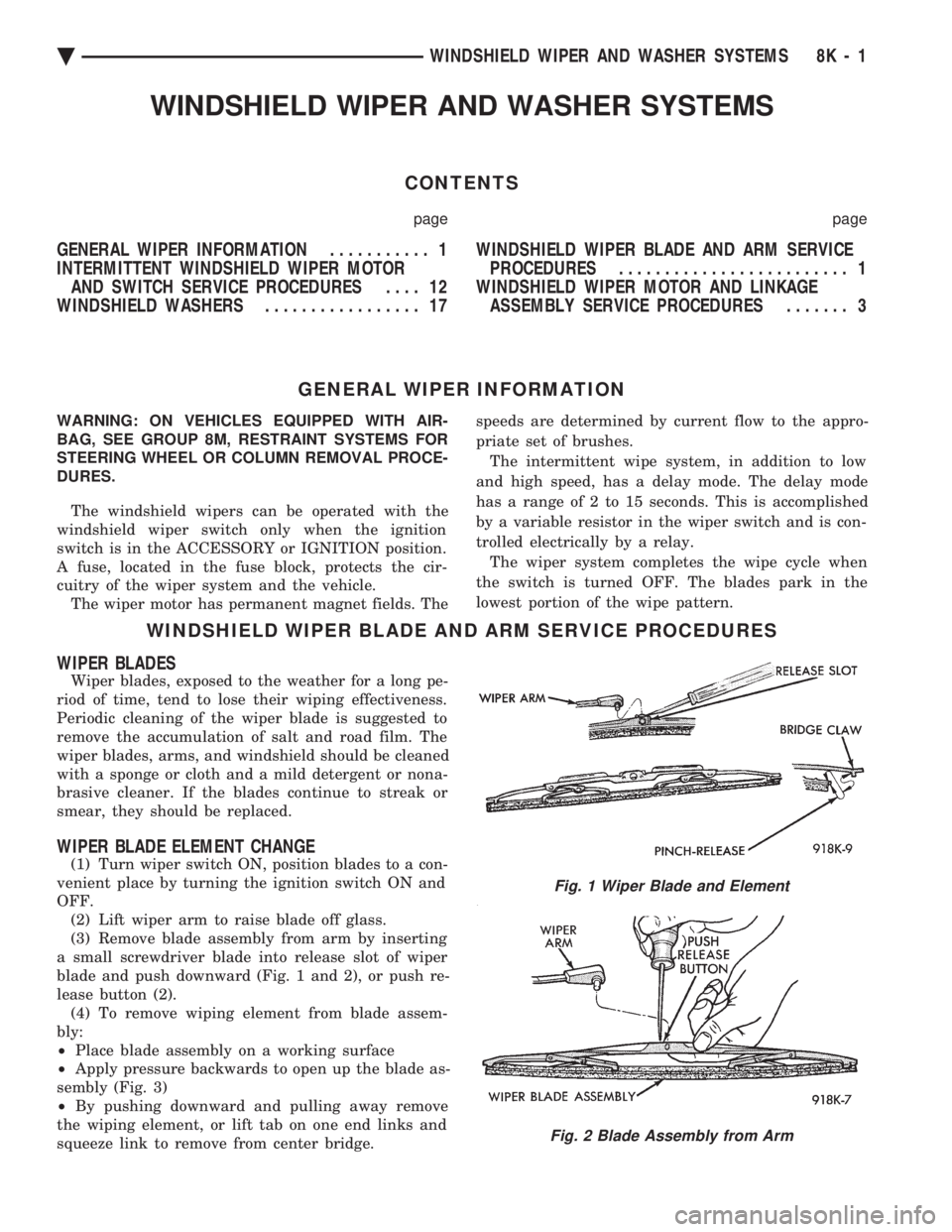
(3) Remove blade assembly from arm by inserting
a small screwdriver blade into release slot of wiper
blade and push downward (Fig. 1 and 2), or push re-
lease button (2). (4) To remove wiping element from blade assem-
bly:
² Place blade assembly on a working surface
² Apply pressure backwards to open up the blade as-
sembly (Fig. 3)
² By pushing downward and pulling away remove
the wiping element, or lift tab on one end links and
squeeze link to remove from center bridge.
Fig. 1 Wiper Blade and Element
Fig. 2 Blade Assembly from Arm
Ä WINDSHIELD WIPER AND WASHER SYSTEMS 8K - 1