1993 CHEVROLET PLYMOUTH ACCLAIM steering wheel
[x] Cancel search: steering wheelPage 1937 of 2438
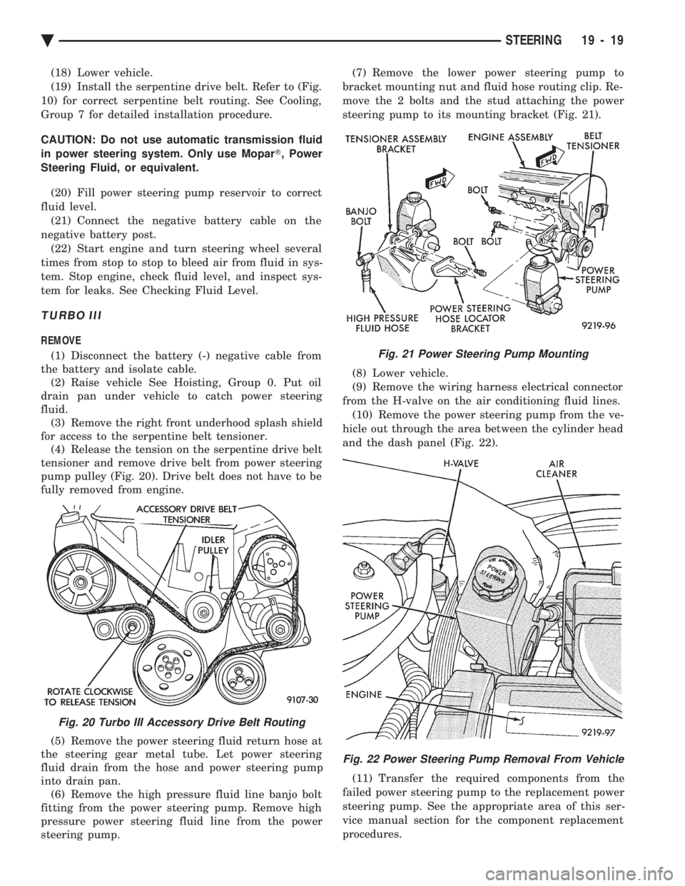
(18) Lower vehicle.
(19) Install the serpentine drive belt. Refer to (Fig.
10) for correct serpentine belt routing. See Cooling,
Group 7 for detailed installation procedure.
CAUTION: Do not use automatic transmission fluid
in power steering system. Only use Mopar T, Power
Steering Fluid, or equivalent.
(20) Fill power steering pump reservoir to correct
fluid level. (21) Connect the negative battery cable on the
negative battery post. (22) Start engine and turn steering wheel several
times from stop to stop to bleed air from fluid in sys-
tem. Stop engine, check fluid level, and inspect sys-
tem for leaks. See Checking Fluid Level.
TURBO III
REMOVE
(1) Disconnect the battery (-) negative cable from
the battery and isolate cable. (2) Raise vehicle See Hoisting, Group 0. Put oil
drain pan under vehicle to catch power steering
fluid. (3) Remove the right front underhood splash shield
for access to the serpentine belt tensioner. (4) Release the tension on the serpentine drive belt
tensioner and remove drive belt from power steering
pump pulley (Fig. 20). Drive belt does not have to be
fully removed from engine.
(5) Remove the power steering fluid return hose at
the steering gear metal tube. Let power steering
fluid drain from the hose and power steering pump
into drain pan. (6) Remove the high pressure fluid line banjo bolt
fitting from the power steering pump. Remove high
pressure power steering fluid line from the power
steering pump. (7) Remove the lower power steering pump to
bracket mounting nut and fluid hose routing clip. Re-
move the 2 bolts and the stud attaching the power
steering pump to its mounting bracket (Fig. 21).
(8) Lower vehicle.
(9) Remove the wiring harness electrical connector
from the H-valve on the air conditioning fluid lines. (10) Remove the power steering pump from the ve-
hicle out through the area between the cylinder head
and the dash panel (Fig. 22).
(11) Transfer the required components from the
failed power steering pump to the replacement power
steering pump. See the appropriate area of this ser-
vice manual section for the component replacement
procedures.
Fig. 20 Turbo III Accessory Drive Belt Routing
Fig. 21 Power Steering Pump Mounting
Fig. 22 Power Steering Pump Removal From Vehicle
Ä STEERING 19 - 19
Page 1938 of 2438
INSTALL (1) Install the power steering pump back into the
vehicle in the reverse order of removal, between cyl-
inder head and dash panel (Fig. 20). (2) Install the wiring harness connector back on
the H-valve located on the air conditioning fluid
lines (Fig. 20). (3) Raise vehicle See Hoisting, Group 0.
(4) Install the power steering pump on its mount-
ing bracket, and the hose locator bracket. Install the
bolt/stud and 2 bolts attaching the power steering
pump to its mounting bracket, and the bolts attach-
ing the hose locator bracket (Fig. 19). Torque all fas-
teners to 31 N Im (280 in. lbs.).
(5) Install the power steering fluid pressure hose,
banjo bolt and seal washer onto power steering pump
(Fig. 4). Pressure hose is to be installed so it is
routed to the left of the hose locator bracket (Fig.
19). Torque the banjo bolt to 31 N Im (275 in. lbs.).
Inspect the O-rings on the banjo bolt to ensure
they are not damaged and located correctly. (6) Install the low pressure fluid return hose from
the power steering pump back on the steel tube on
the steering gear (Fig. 4). Install hose clamp, be sure
the hose clamp is installed past the retaining bead
the steel tube. Install the hose routing clip on the
power steering pump bolt/stud, install clip retaining
nut and tighten. (7) Install the serpentine accessory drive belt (Fig.
18). Be sure the belt is correctly installed and
aligned on all pulleys before starting engine. (8) Install the right front underhood splash shield.
CAUTION: Do not use automatic transmission fluid
in power steering system. Only use Mopar T, Power
Steering Fluid, or equivalent.
(9) Fill power steering pump reservoir to correct
fluid level. (10) Connect the negative battery cable on the
negative battery post. (11) Start engine and turn steering wheel several
times from stop to stop to bleed air from fluid in sys-
tem. Stop engine, check fluid level, and inspect sys-
tem for leaks. See Checking Fluid Level.
POWER STEERING PUMP PULLEY SERVICE
SAGINAW VANE SUBMERGED PUMP
REMOVE
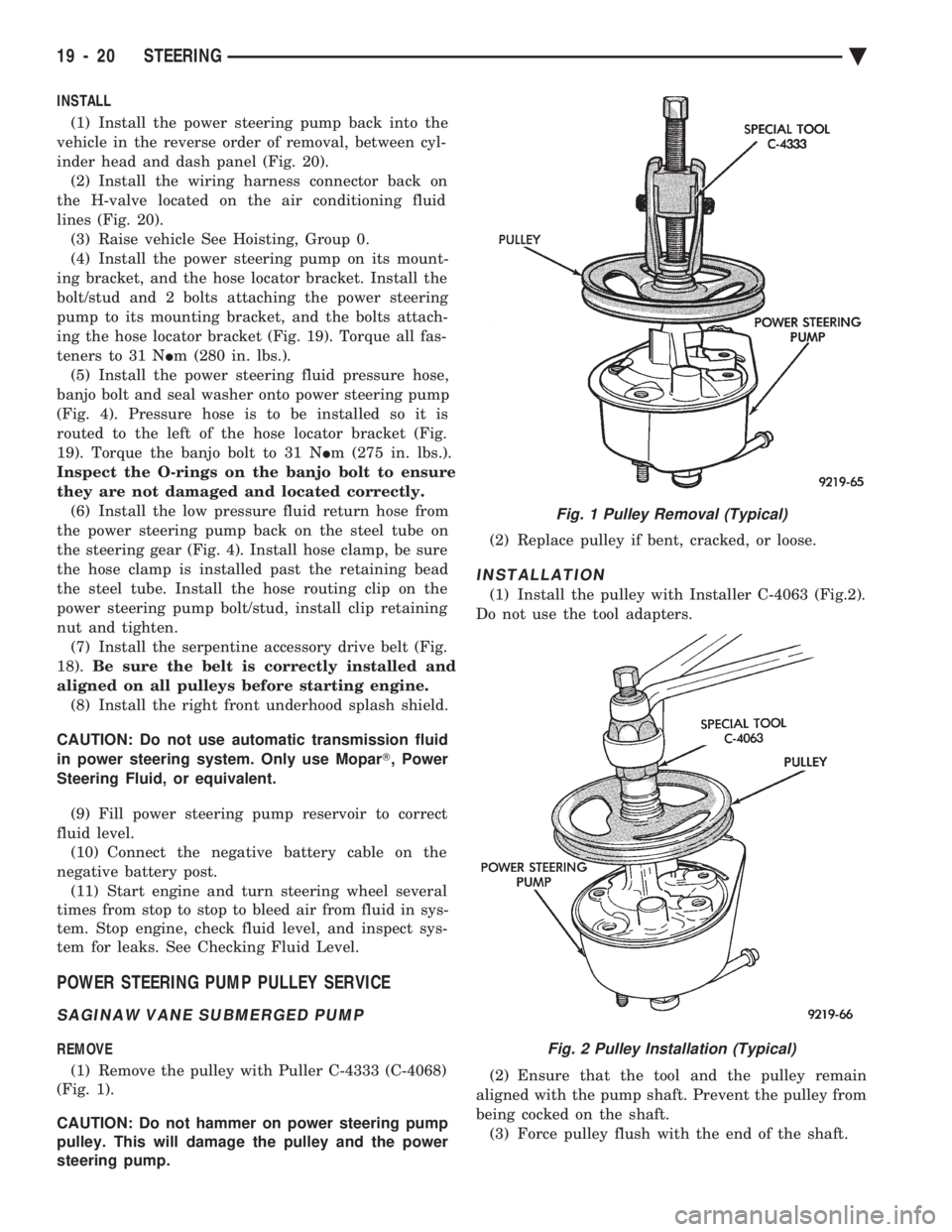
(1) Remove the pulley with Puller C-4333 (C-4068)
(Fig. 1).
CAUTION: Do not hammer on power steering pump
pulley. This will damage the pulley and the power
steering pump. (2) Replace pulley if bent, cracked, or loose.
INSTALLATION
(1) Install the pulley with Installer C-4063 (Fig.2).
Do not use the tool adapters.
(2) Ensure that the tool and the pulley remain
aligned with the pump shaft. Prevent the pulley from
being cocked on the shaft. (3) Force pulley flush with the end of the shaft.
Fig. 1 Pulley Removal (Typical)
Fig. 2 Pulley Installation (Typical)
19 - 20 STEERING Ä
Page 1942 of 2438
POWER STEERING PUMPÐINITIAL OPERATION
CAUTION: The fluid level should be checked with
engine off to prevent injury from moving compo-
nents. Use only Mopar TPower Steering Fluid. Do
not use automatic transmission fluid. Do not over-
fill.
Wipe filler cap clean, then check the fluid level.
The dipstick should indicate FULL COLDwhen the
fluid is at normal temperature of approximately 21ÉC
to 27ÉC (70ÉF to 80ÉF). (1) Fill power steering pump fluid reservoir to the
proper level. (2) Start the engine and let run for a few seconds.
Then turn the engine off.
(3) Add fluid if necessary. Repeat the above proce-
dure until the fluid level remains constant after run-
ning the engine. (4) Raise front wheels of vehicle off the ground.
(5) Start the engine. Slowly turn the steering
wheel right and left, lightly contacting the wheel
stops. Then turn the engine off. (6) Add power steering fluid if necessary.
(7) Lower the vehicle and turn the steering wheel
slowly from lock to lock. (8) Stop the engine. Check the fluid level and refill
as required. (9) If the fluid is extremely foamy, allow the vehi-
cle to stand a few minutes and repeat the above pro-
cedure.
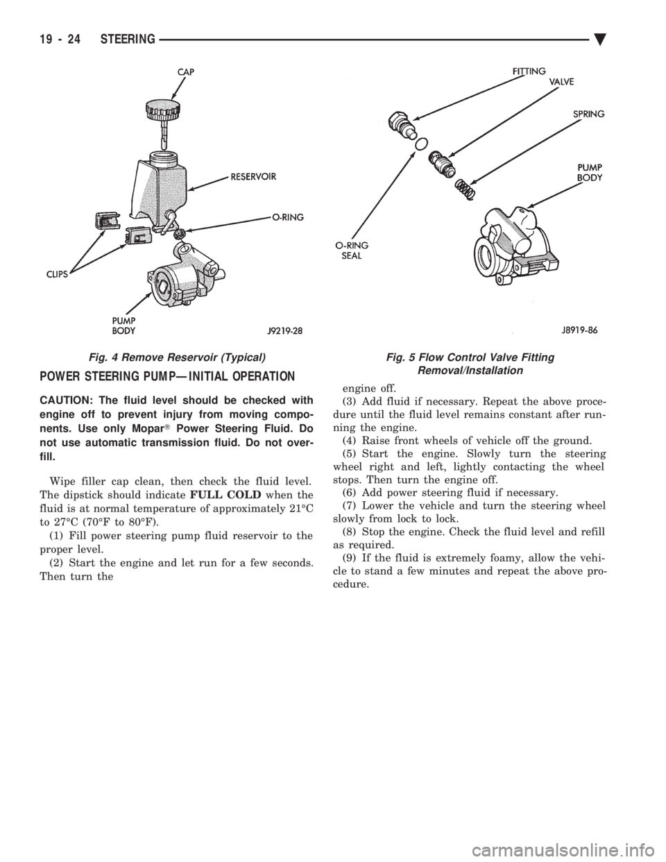
Fig. 4 Remove Reservoir (Typical)Fig. 5 Flow Control Valve Fitting Removal/Installation
19 - 24 STEERING Ä
Page 1943 of 2438
POWER STEERING GEAR INDEX
page page
General Information ....................... 25
Outer Tie Rod ........................... 27 Steering Gear Service
..................... 25
GENERAL INFORMATION
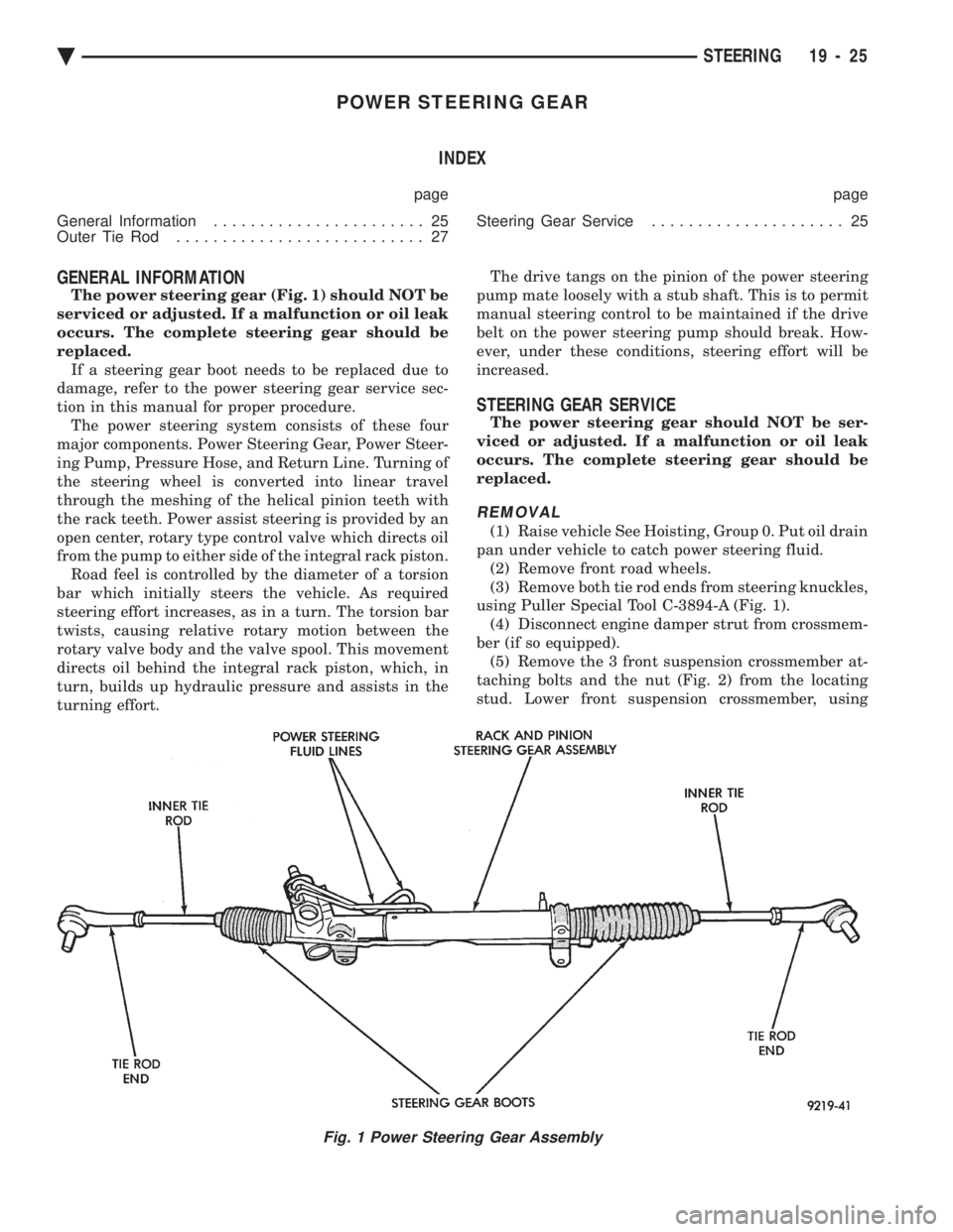
The power steering gear (Fig. 1) should NOT be
serviced or adjusted. If a malfunction or oil leak
occurs. The complete steering gear should be
replaced. If a steering gear boot needs to be replaced due to
damage, refer to the power steering gear service sec-
tion in this manual for proper procedure. The power steering system consists of these four
major components. Power Steering Gear, Power Steer-
ing Pump, Pressure Hose, and Return Line. Turning of
the steering wheel is converted into linear travel
through the meshing of the helical pinion teeth with
the rack teeth. Power assist steering is provided by an
open center, rotary type control valve which directs oil
from the pump to either side of the integral rack piston. Road feel is controlled by the diameter of a torsion
bar which initially steers the vehicle. As required
steering effort increases, as in a turn. The torsion bar
twists, causing relative rotary motion between the
rotary valve body and the valve spool. This movement
directs oil behind the integral rack piston, which, in
turn, builds up hydraulic pressure and assists in the
turning effort. The drive tangs on the pinion of the power steering
pump mate loosely with a stub shaft. This is to permit
manual steering control to be maintained if the drive
belt on the power steering pump should break. How-
ever, under these conditions, steering effort will be
increased.
STEERING GEAR SERVICE
The power steering gear should NOT be ser-
viced or adjusted. If a malfunction or oil leak
occurs. The complete steering gear should be
replaced.
REMOVAL
(1) Raise vehicle See Hoisting, Group 0. Put oil drain
pan under vehicle to catch power steering fluid. (2) Remove front road wheels.
(3) Remove both tie rod ends from steering knuckles,
using Puller Special Tool C-3894-A (Fig. 1). (4) Disconnect engine damper strut from crossmem-
ber (if so equipped). (5) Remove the 3 front suspension crossmember at-
taching bolts and the nut (Fig. 2) from the locating
stud. Lower front suspension crossmember, using
Fig. 1 Power Steering Gear Assembly
Ä STEERING 19 - 25
Page 1945 of 2438
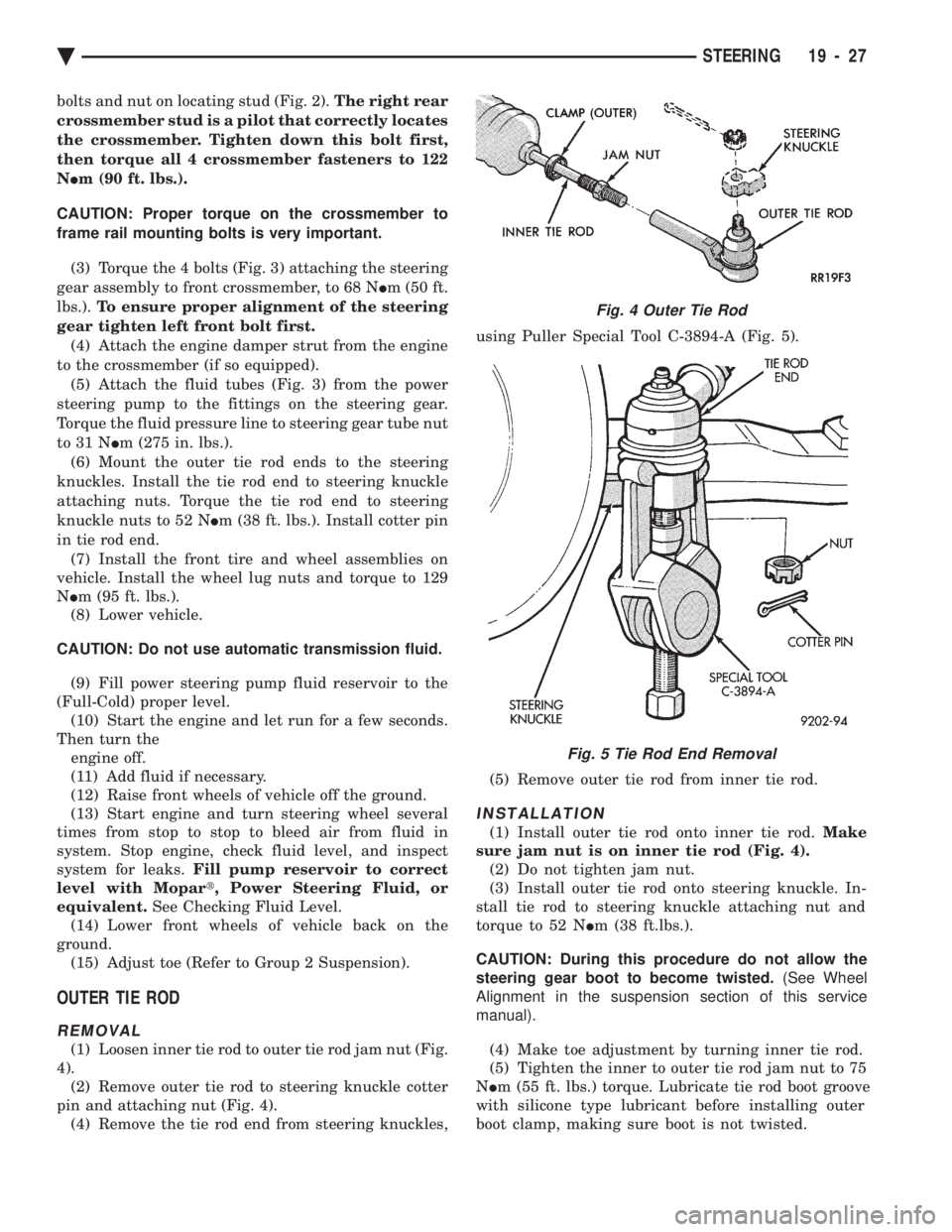
bolts and nut on locating stud (Fig. 2). The right rear
crossmember stud is a pilot that correctly locates
the crossmember. Tighten down this bolt first,
then torque all 4 crossmember fasteners to 122
N Im (90 ft. lbs.).
CAUTION: Proper torque on the crossmember to
frame rail mounting bolts is very important.
(3) Torque the 4 bolts (Fig. 3) attaching the steering
gear assembly to front crossmember, to 68 N Im (50 ft.
lbs.). To ensure proper alignment of the steering
gear tighten left front bolt first. (4) Attach the engine damper strut from the engine
to the crossmember (if so equipped). (5) Attach the fluid tubes (Fig. 3) from the power
steering pump to the fittings on the steering gear.
Torque the fluid pressure line to steering gear tube nut
to 31 N Im (275 in. lbs.).
(6) Mount the outer tie rod ends to the steering
knuckles. Install the tie rod end to steering knuckle
attaching nuts. Torque the tie rod end to steering
knuckle nuts to 52 N Im (38 ft. lbs.). Install cotter pin
in tie rod end. (7) Install the front tire and wheel assemblies on
vehicle. Install the wheel lug nuts and torque to 129
N Im (95 ft. lbs.).
(8) Lower vehicle.
CAUTION: Do not use automatic transmission fluid. (9) Fill power steering pump fluid reservoir to the
(Full-Cold) proper level. (10) Start the engine and let run for a few seconds.
Then turn the engine off.
(11) Add fluid if necessary.
(12) Raise front wheels of vehicle off the ground.
(13) Start engine and turn steering wheel several
times from stop to stop to bleed air from fluid in
system. Stop engine, check fluid level, and inspect
system for leaks. Fill pump reservoir to correct
level with Mopar t, Power Steering Fluid, or
equivalent. See Checking Fluid Level.
(14) Lower front wheels of vehicle back on the
ground. (15) Adjust toe (Refer to Group 2 Suspension).
OUTER TIE ROD
REMOVAL
(1) Loosen inner tie rod to outer tie rod jam nut (Fig.
4). (2) Remove outer tie rod to steering knuckle cotter
pin and attaching nut (Fig. 4). (4) Remove the tie rod end from steering knuckles, using Puller Special Tool C-3894-A (Fig. 5).
(5) Remove outer tie rod from inner tie rod.
INSTALLATION
(1) Install outer tie rod onto inner tie rod. Make
sure jam nut is on inner tie rod (Fig. 4). (2) Do not tighten jam nut.
(3) Install outer tie rod onto steering knuckle. In-
stall tie rod to steering knuckle attaching nut and
torque to 52 N Im (38 ft.lbs.).
CAUTION: During this procedure do not allow the
steering gear boot to become twisted. (See Wheel
Alignment in the suspension section of this service
manual).
(4) Make toe adjustment by turning inner tie rod.
(5) Tighten the inner to outer tie rod jam nut to 75
N Im (55 ft. lbs.) torque. Lubricate tie rod boot groove
with silicone type lubricant before installing outer
boot clamp, making sure boot is not twisted.
Fig. 4 Outer Tie Rod
Fig. 5 Tie Rod End Removal
Ä STEERING 19 - 27
Page 1948 of 2438
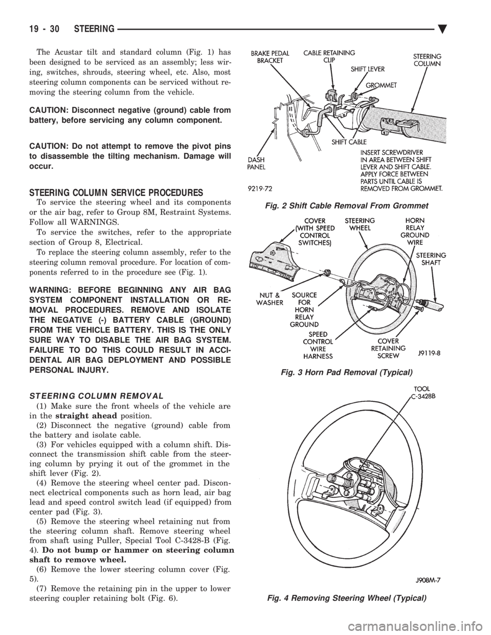
The Acustar tilt and standard column (Fig. 1) has
been designed to be serviced as an assembly; less wir-
ing, switches, shrouds, steering wheel, etc. Also, most
steering column components can be serviced without re-
moving the steering column from the vehicle.
CAUTION: Disconnect negative (ground) cable from
battery, before servicing any column component.
CAUTION: Do not attempt to remove the pivot pins
to disassemble the tilting mechanism. Damage will
occur.
STEERING COLUMN SERVICE PROCEDURES
To service the steering wheel and its components
or the air bag, refer to Group 8M, Restraint Systems.
Follow all WARNINGS. To service the switches, refer to the appropriate
section of Group 8, Electrical.
To replace the steering column assembly, refer to the
steering column removal procedure. For location of com-
ponents referred to in the procedure see (Fig. 1).
WARNING: BEFORE BEGINNING ANY AIR BAG
SYSTEM COMPONENT INSTALLATION OR RE-
MOVAL PROCEDURES. REMOVE AND ISOLATE
THE NEGATIVE (-) BATTERY CABLE (GROUND)
FROM THE VEHICLE BATTERY. THIS IS THE ONLY
SURE WAY TO DISABLE THE AIR BAG SYSTEM.
FAILURE TO DO THIS COULD RESULT IN ACCI-
DENTAL AIR BAG DEPLOYMENT AND POSSIBLE
PERSONAL INJURY.
STEERING COLUMN REMOVAL
(1) Make sure the front wheels of the vehicle are
in the straight ahead position.
(2) Disconnect the negative (ground) cable from
the battery and isolate cable. (3) For vehicles equipped with a column shift. Dis-
connect the transmission shift cable from the steer-
ing column by prying it out of the grommet in the
shift lever (Fig. 2). (4) Remove the steering wheel center pad. Discon-
nect electrical components such as horn lead, air bag
lead and speed control switch lead (if equipped) from
center pad (Fig. 3). (5) Remove the steering wheel retaining nut from
the steering column shaft. Remove steering wheel
from shaft using Puller, Special Tool C-3428-B (Fig.
4). Do not bump or hammer on steering column
shaft to remove wheel. (6) Remove the lower steering column cover (Fig.
5). (7) Remove the retaining pin in the upper to lower
steering coupler retaining bolt (Fig. 6).
Fig. 2 Shift Cable Removal From Grommet
Fig. 3 Horn Pad Removal (Typical)
Fig. 4 Removing Steering Wheel (Typical)
19 - 30 STEERING Ä
Page 1951 of 2438
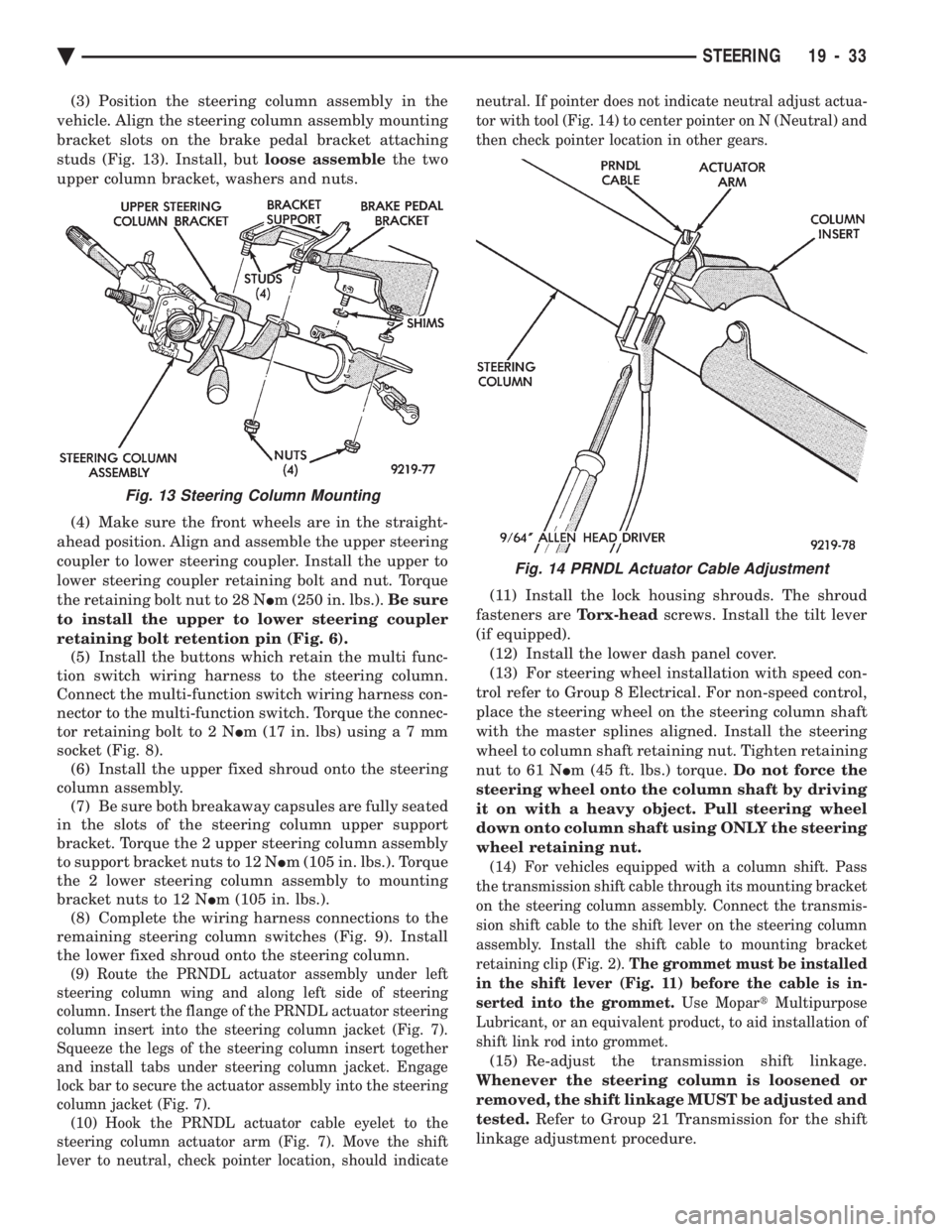
(3) Position the steering column assembly in the
vehicle. Align the steering column assembly mounting
bracket slots on the brake pedal bracket attaching
studs (Fig. 13). Install, but loose assemblethe two
upper column bracket, washers and nuts.
(4) Make sure the front wheels are in the straight-
ahead position. Align and assemble the upper steering
coupler to lower steering coupler. Install the upper to
lower steering coupler retaining bolt and nut. Torque
the retaining bolt nut to 28 N Im (250 in. lbs.). Be sure
to install the upper to lower steering coupler
retaining bolt retention pin (Fig. 6). (5) Install the buttons which retain the multi func-
tion switch wiring harness to the steering column.
Connect the multi-function switch wiring harness con-
nector to the multi-function switch. Torque the connec-
tor retaining bolt to 2 N Im (17 in. lbs) usin ga7mm
socket (Fig. 8). (6) Install the upper fixed shroud onto the steering
column assembly. (7) Be sure both breakaway capsules are fully seated
in the slots of the steering column upper support
bracket. Torque the 2 upper steering column assembly
to support bracket nuts to 12 N Im (105 in. lbs.). Torque
the 2 lower steering column assembly to mounting
bracket nuts to 12 N Im (105 in. lbs.).
(8) Complete the wiring harness connections to the
remaining steering column switches (Fig. 9). Install
the lower fixed shroud onto the steering column.
(9) Route the PRNDL actuator assembly under left
steering column wing and along left side of steering
column. Insert the flange of the PRNDL actuator steering
column insert into the steering column jacket (Fig. 7).
Squeeze the legs of the steering column insert together
and install tabs under steering column jacket. Engage
lock bar to secure the actuator assembly into the steering
column jacket (Fig. 7). (10) Hook the PRNDL actuator cable eyelet to the
steering column actuator arm (Fig. 7). Move the shift
lever to neutral, check pointer location, should indicate neutral. If pointer does not indicate neutral adjust actua-
tor with tool (Fig. 14) to center pointer on N (Neutral) and
then check pointer location in other gears.
(11) Install the lock housing shrouds. The shroud
fasteners are Torx-headscrews. Install the tilt lever
(if equipped). (12) Install the lower dash panel cover.
(13) For steering wheel installation with speed con-
trol refer to Group 8 Electrical. For non-speed control,
place the steering wheel on the steering column shaft
with the master splines aligned. Install the steering
wheel to column shaft retaining nut. Tighten retaining
nut to 61 N Im (45 ft. lbs.) torque. Do not force the
steering wheel onto the column shaft by driving
it on with a heavy object. Pull steering wheel
down onto column shaft using ONLY the steering
wheel retaining nut.
(14) For vehicles equipped with a column shift. Pass
the transmission shift cable through its mounting bracket
on the steering column assembly. Connect the transmis-
sion shift cable to the shift lever on the steering column
assembly. Install the shift cable to mounting bracket
retaining clip (Fig. 2). The grommet must be installed
in the shift lever (Fig. 11) before the cable is in-
serted into the grommet. Use MopartMultipurpose
Lubricant, or an equivalent product, to aid installation of
shift link rod into grommet.
(15) Re-adjust the transmission shift linkage.
Whenever the steering column is loosened or
removed, the shift linkage MUST be adjusted and
tested. Refer to Group 21 Transmission for the shift
linkage adjustment procedure.
Fig. 13 Steering Column Mounting
Fig. 14 PRNDL Actuator Cable Adjustment
Ä STEERING 19 - 33
Page 1952 of 2438
(16) Connect the battery ground (negative) cable.
Test the operation of the lights and horns. If applica-
ble, reset the clock and radio.
STEERING COLUMN COMPONENT SERVICE
The Acustar tilt and standard steering columns
(Fig.1) have been designed to be serviced as an as-
sembly; less wiring, switches, shrouds, steering
wheel, etc. Also most steering column components
can be serviced without removing the steering col-
umn from the vehicle. For additional information on
electrical components refer to Group 8H Electrical.
GEAR SHIFT LEVER
The gear shift lever (if equipped) is a serviceable
component of the Acustar steering column assembly.
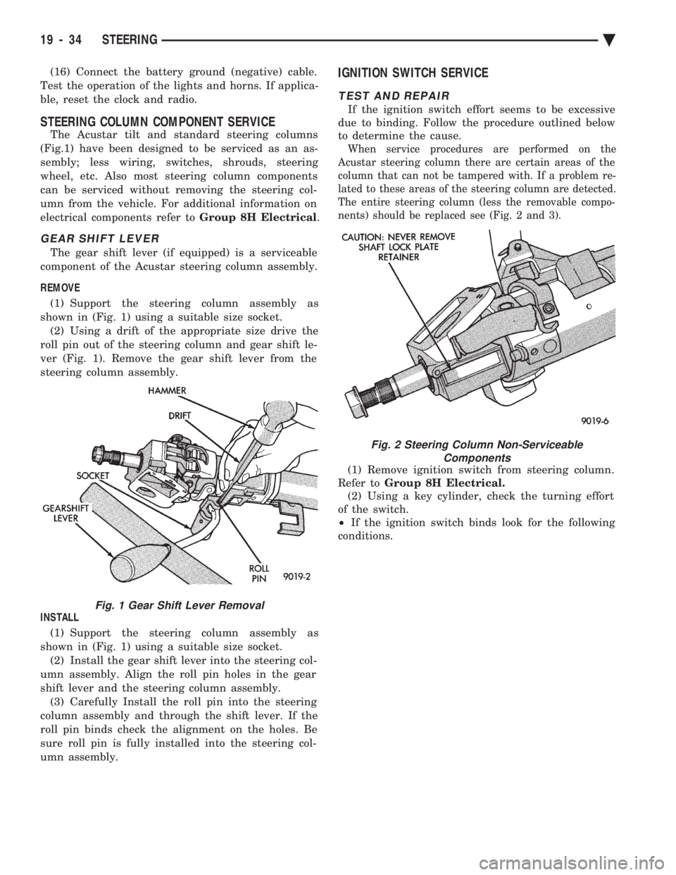
REMOVE (1) Support the steering column assembly as
shown in (Fig. 1) using a suitable size socket. (2) Using a drift of the appropriate size drive the
roll pin out of the steering column and gear shift le-
ver (Fig. 1). Remove the gear shift lever from the
steering column assembly.
INSTALL (1) Support the steering column assembly as
shown in (Fig. 1) using a suitable size socket. (2) Install the gear shift lever into the steering col-
umn assembly. Align the roll pin holes in the gear
shift lever and the steering column assembly. (3) Carefully Install the roll pin into the steering
column assembly and through the shift lever. If the
roll pin binds check the alignment on the holes. Be
sure roll pin is fully installed into the steering col-
umn assembly.
IGNITION SWITCH SERVICE
TEST AND REPAIR
If the ignition switch effort seems to be excessive
due to binding. Follow the procedure outlined below
to determine the cause.
When service procedures are performed on the
Acustar steering column there are certain areas of the
column that can not be tampered with. If a problem re-
lated to these areas of the steering column are detected.
The entire steering column (less the removable compo-
nents) should be replaced see (Fig. 2 and 3).
(1) Remove ignition switch from steering column.
Refer to Group 8H Electrical.
(2) Using a key cylinder, check the turning effort
of the switch.
² If the ignition switch binds look for the following
conditions.
Fig. 1 Gear Shift Lever Removal
Fig. 2 Steering Column Non-Serviceable Components
19 - 34 STEERING Ä