Page 1783 of 4087
(g) Using SST and a hammer, tap in a new guide bushinguntil the snap ring makes contact with the cylinder head.
SST 09201±70010
HINT: Different the bushings are used for the intake and ex-
haust.
(h) Using a sharp 6 mm reamer, ream the guide bushing to obtain the standard specified clearance (See page
EM±80 ) between the guide bushing and valve stem.
7. INSPECT AND GRIND VALVES (a) Grind the valve enough to remove pits and carbon.
(b) Check that the valve is ground to the correct valve faceangle.
Valve face angle: 44.5 5
(c) Check the valve head margin thickness.
Standard margin thickness: 1.0 mm (0.039 in.)
Minimum margin thickness: 0.5 mm (0.020 in.)
If the margin thickness is less than minimum, replace the
valve.
EM±82
±
ENGINE MECHANICAL Cylinder Heads
WhereEverybodyKnowsYourName
Page 1784 of 4087
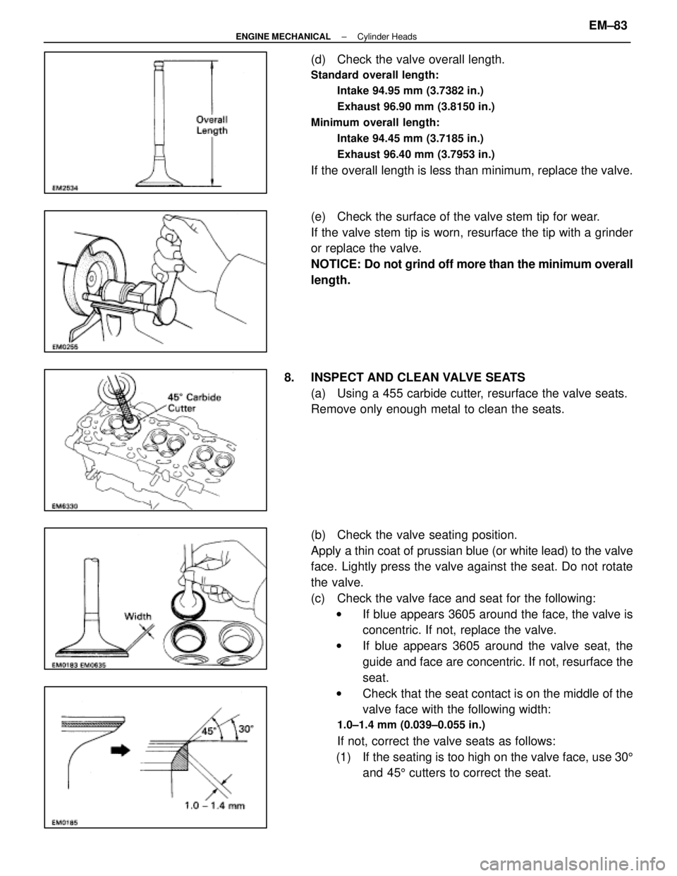
(d) Check the valve overall length.
Standard overall length:Intake 94.95 mm (3.7382 in.)
Exhaust 96.90 mm (3.8150 in.)
Minimum overall length: Intake 94.45 mm (3.7185 in.)
Exhaust 96.40 mm (3.7953 in.)
If the overall length is less than minimum, replace the valve.
(e) Check the surface of the valve stem tip for wear.
If the valve stem tip is worn, resurface the tip with a grinder
or replace the valve.
NOTICE: Do not grind off more than the minimum overall
length.
8. INSPECT AND CLEAN VALVE SEATS (a) Using a 455 carbide cutter, resurface the valve seats.
Remove only enough metal to clean the seats.
(b) Check the valve seating position.
Apply a thin coat of prussian blue (or white lead) to the valve
face. Lightly press the valve against the seat. Do not rotate
the valve.
(c) Check the valve face and seat for the following:w If blue appears 3605 around the face, the valve is
concentric. If not, replace the valve.
w If blue appears 3605 around the valve seat, the
guide and face are concentric. If not, resurface the
seat.
w Check that the seat contact is on the middle of the
valve face with the following width:
1.0±1.4 mm (0.039±0.055 in.)
If not, correct the valve seats as follows:
(1) If the seating is too high on the valve face, use 30 5
and 45 5 cutters to correct the seat.
±
ENGINE MECHANICAL Cylinder HeadsEM±83
WhereEverybodyKnowsYourName
Page 1786 of 4087
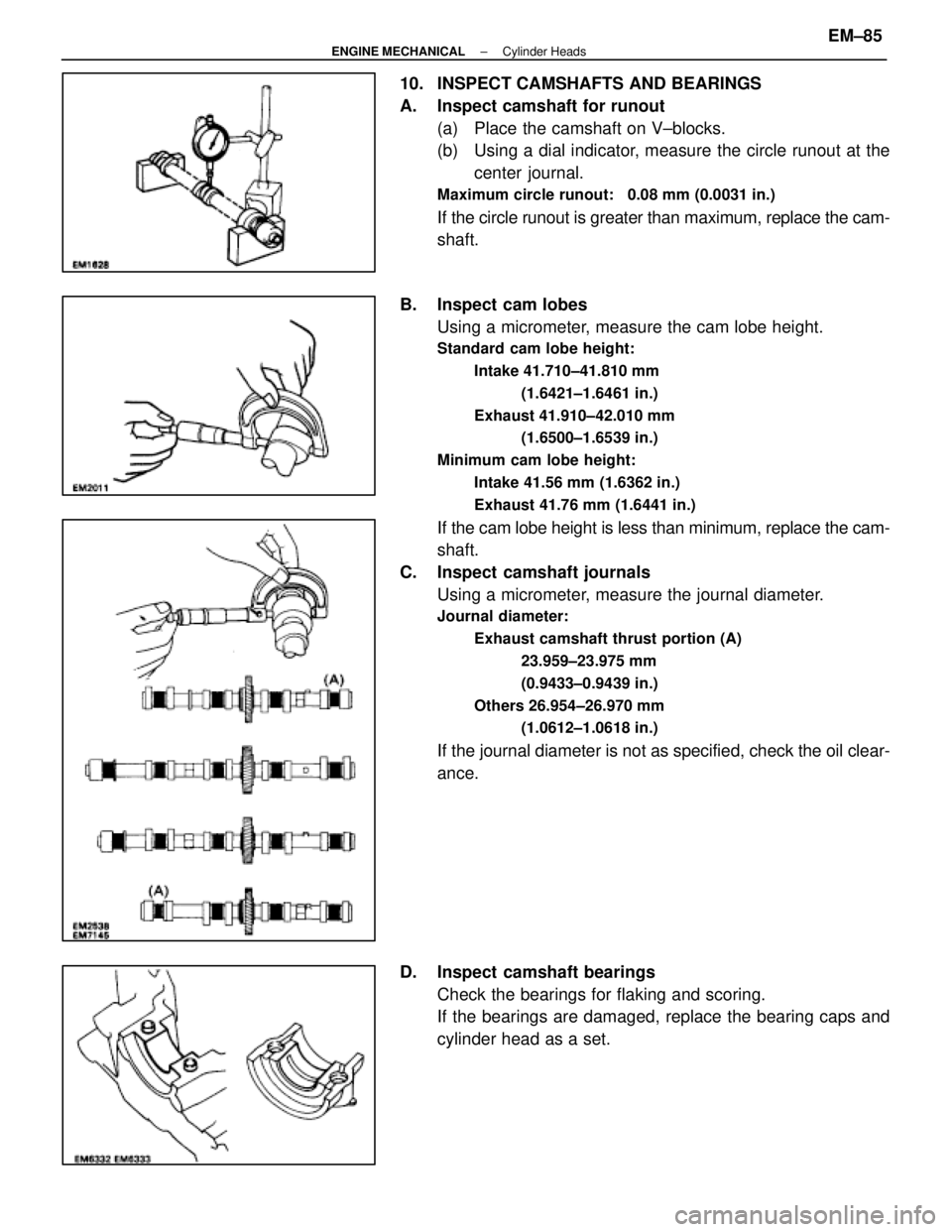
10. INSPECT CAMSHAFTS AND BEARINGS
A. Inspect camshaft for runout(a) Place the camshaft on V±blocks.
(b) Using a dial indicator, measure the circle runout at thecenter journal.
Maximum circle runout: 0.08 mm (0.0031 in.)
If the circle runout is greater than maximum, replace the cam-
shaft.
B. Inspect cam lobes Using a micrometer, measure the cam lobe height.
Standard cam lobe height:
Intake 41.710±41.810 mm (1.6421±1.6461 in.)
Exhaust 41.910±42.010 mm (1.6500±1.6539 in.)
Minimum cam lobe height: Intake 41.56 mm (1.6362 in.)
Exhaust 41.76 mm (1.6441 in.)
If the cam lobe height is less than minimum, replace the cam-
shaft.
C. Inspect camshaft journals Using a micrometer, measure the journal diameter.
Journal diameter:
Exhaust camshaft thrust portion (A) 23.959±23.975 mm
(0.9433±0.9439 in.)
Others 26.954±26.970 mm (1.0612±1.0618 in.)
If the journal diameter is not as specified, check the oil clear-
ance.
D. Inspect camshaft bearings Check the bearings for flaking and scoring.
If the bearings are damaged, replace the bearing caps and
cylinder head as a set.
±
ENGINE MECHANICAL Cylinder HeadsEM±85
WhereEverybodyKnowsYourName
Page 1791 of 4087
2. INSTALL VALVES(a) Using SST, push in a new oil seal.
SST 09201±41020
(b) Install the following parts:(1) Valve
(2) Spring seat
(3) Valve spring
(4) Spring retainer
(c) Using SST, compress the valve spring and place the two
keepers around the valve stem.
SST 09202±70010
(d) Using a plastic±faced hammer, lightly tap the valve stem
tip to assure proper fit.
3. INSTALL VALVE LIFTERS AND SHIMS Check the valve lifter rotates smoothly by hand.
EM±90
±
ENGINE MECHANICAL Cylinder Heads
WhereEverybodyKnowsYourName
Page 1794 of 4087
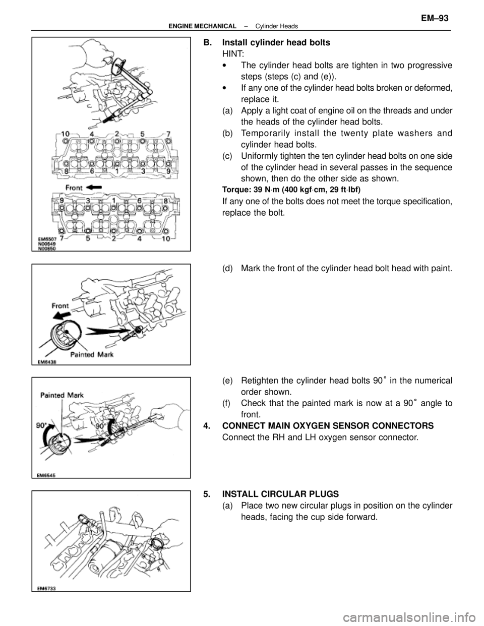
B. Install cylinder head boltsHINT:
wThe cylinder head bolts are tighten in two progressive
steps (steps (c) and (e)).
w If any one of the cylinder head bolts broken or deformed,
replace it.
(a) Apply a light coat of engine oil on the threads and under
the heads of the cylinder head bolts.
(b) Te mp o ra rily in sta ll th e twe n ty pla te wa sh e rs an d cylinder head bolts.
(c) Uniformly tighten the ten cylinder head bolts on one side
of the cylinder head in several passes in the sequence
shown, then do the other side as shown.
Torque: 39 N Vm (400 kgf Vcm, 29 ft Vlbf)
If any one of the bolts does not meet the torque specification,
replace the bolt.
(d) Mark the front of the cylinder head bolt head with paint.
(e) Retighten the cylinder head bolts 90 ° in the numerical
order shown.
(f) Check that the painted mark is now at a 90 ° angle to
front.
4. CONNECT MAIN OXYGEN SENSOR CONNECTORS Connect the RH and LH oxygen sensor connector.
5. INSTALL CIRCULAR PLUGS (a) Place two new circular plugs in position on the cylinderheads, facing the cup side forward.
±
ENGINE MECHANICAL Cylinder HeadsEM±93
WhereEverybodyKnowsYourName
Page 1798 of 4087
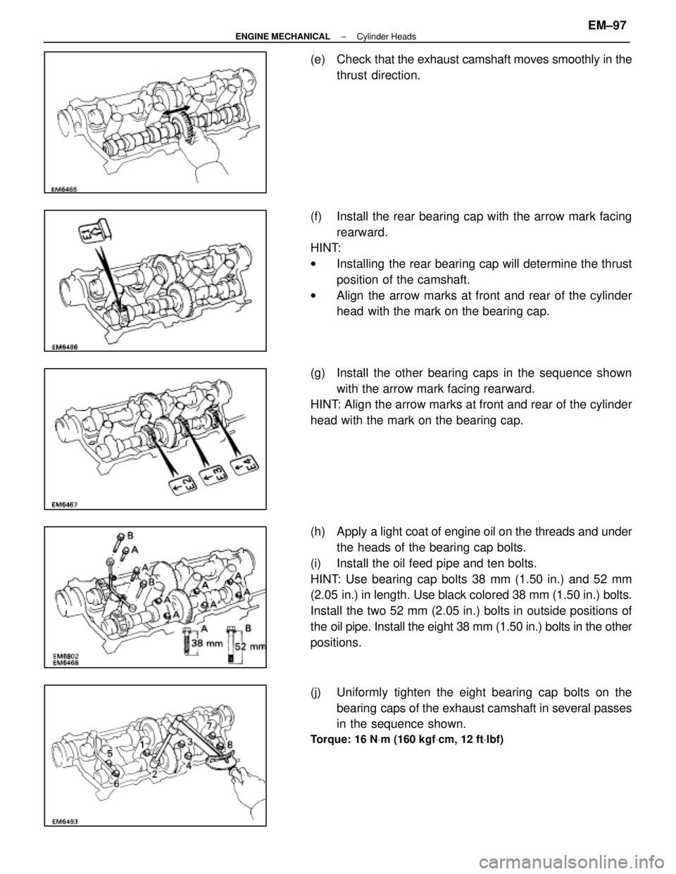
(e) Check that the exhaust camshaft moves smoothly in the
thrust direction.
(f) Install the rear bearing cap with the arrow mark facing rearward.
HINT:
w Installing the rear bearing cap will determine the thrust
position of the camshaft.
w Align the arrow marks at front and rear of the cylinder
head with the mark on the bearing cap.
(g) Install the other bearing caps in the sequence shown with the arrow mark facing rearward.
HINT: Align the arrow marks at front and rear of the cylinder
head with the mark on the bearing cap.
(h) Apply a light coat of engine oil on the threads and under
the heads of the bearing cap bolts.
(i) Install the oil feed pipe and ten bolts.
HINT: Use bearing cap bolts 38 mm (1.50 in.) and 52 mm
(2.05 in.) in length. Use black colored 38 mm (1.50 in.) bolts.
Install the two 52 mm (2.05 in.) bolts in outside positions of
the oil pipe. Install the eight 38 mm (1.50 in.) bolts in the other
positions.
(j) Uniformly tighten the eight bearing cap bolts on the bearing caps of the exhaust camshaft in several passes
in the sequence shown.
Torque: 16 N Vm (160 kgf Vcm, 12 ft Vlbf)
±
ENGINE MECHANICAL Cylinder HeadsEM±97
WhereEverybodyKnowsYourName
Page 1801 of 4087
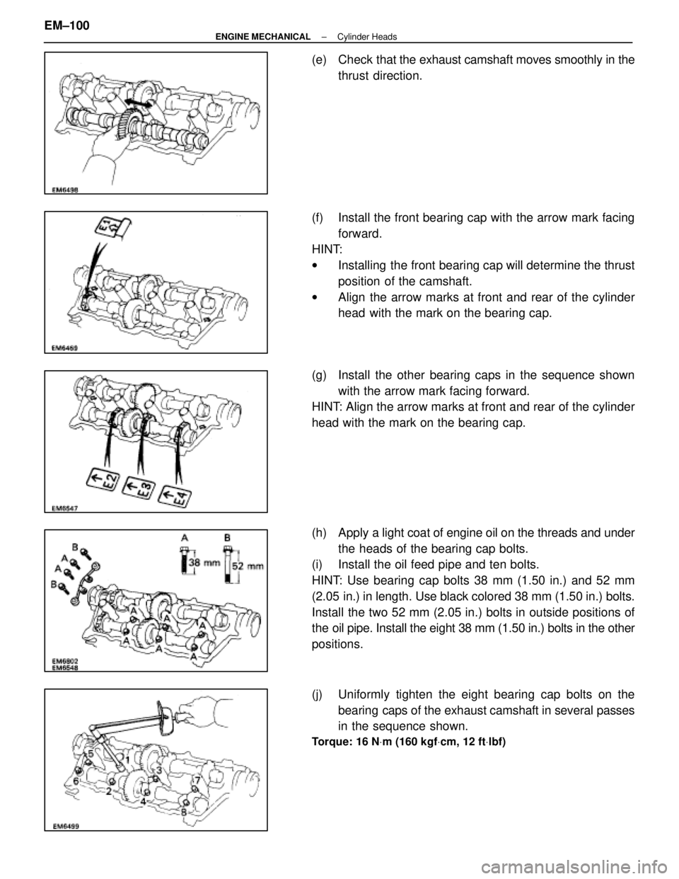
(e) Check that the exhaust camshaft moves smoothly in the
thrust direction.
(f) Install the front bearing cap with the arrow mark facing forward.
HINT:
w Installing the front bearing cap will determine the thrust
position of the camshaft.
w Align the arrow marks at front and rear of the cylinder
head with the mark on the bearing cap.
(g) Install the other bearing caps in the sequence shown with the arrow mark facing forward.
HINT: Align the arrow marks at front and rear of the cylinder
head with the mark on the bearing cap.
(h) Apply a light coat of engine oil on the threads and under
the heads of the bearing cap bolts.
(i) Install the oil feed pipe and ten bolts.
HINT: Use bearing cap bolts 38 mm (1.50 in.) and 52 mm
(2.05 in.) in length. Use black colored 38 mm (1.50 in.) bolts.
Install the two 52 mm (2.05 in.) bolts in outside positions of
the oil pipe. Install the eight 38 mm (1.50 in.) bolts in the other
positions.
(j) Uniformly tighten the eight bearing cap bolts on the
bearing caps of the exhaust camshaft in several passes
in the sequence shown.
Torque: 16 N Vm (160 kgf Vcm, 12 ft Vlbf)
EM±100±
ENGINE MECHANICAL Cylinder Heads
WhereEverybodyKnowsYourName
Page 1802 of 4087
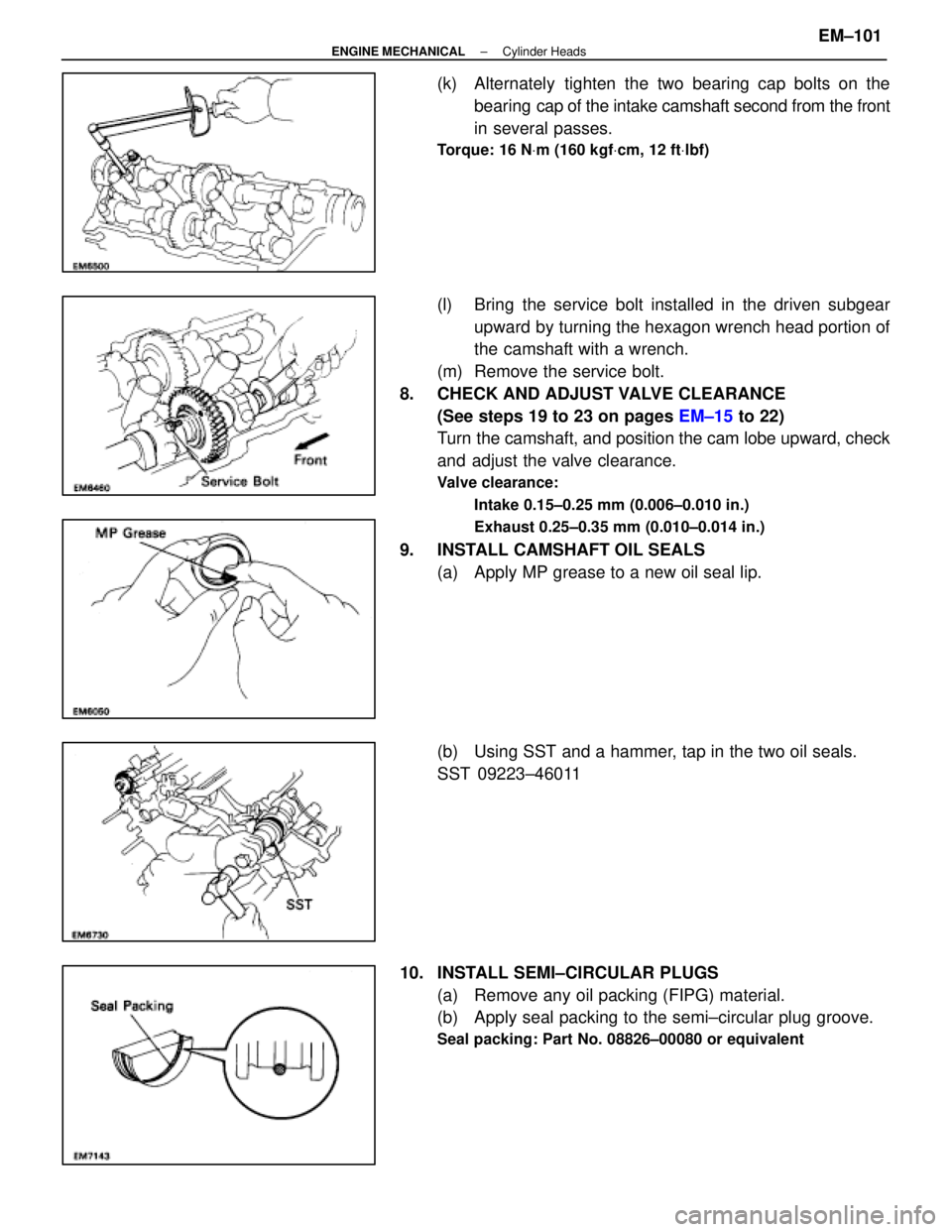
(k) Alternately tighten the two bearing cap bolts on thebearing cap of the intake camshaft second from the front
in several passes.
Torque: 16 N Vm (160 kgf Vcm, 12 ft Vlbf)
(l) Bring the service bolt installed in the driven subgear
upward by turning the hexagon wrench head portion of
the camshaft with a wrench.
(m) Remove the service bolt.
8. CHECK AND ADJUST VALVE CLEARANCE (See steps 19 to 23 on pages EM±15 to 22)
Turn the camshaft, and position the cam lobe upward, check
and adjust the valve clearance.
Valve clearance:
Intake 0.15±0.25 mm (0.006±0.010 in.)
Exhaust 0.25±0.35 mm (0.010±0.014 in.)
9. INSTALL CAMSHAFT OIL SEALS(a) Apply MP grease to a new oil seal lip.
(b) Using SST and a hammer, tap in the two oil seals.
SST 09223±46011
10. INSTALL SEMI±CIRCULAR PLUGS (a) Remove any oil packing (FIPG) material.
(b) Apply seal packing to the semi±circular plug groove.
Seal packing: Part No. 08826±00080 or equivalent
±
ENGINE MECHANICAL Cylinder HeadsEM±101
WhereEverybodyKnowsYourName