Page 1806 of 4087
22. INSTALL DELIVERY PIPES AND INJECTORS(a) Install the grommet and a new O±ring to each injector.
(b) W h i l e t u r n i n g t h e I n j e c t o r c l o c k w i s e a n dcounterclockwise, push it to delivery pipe. Install the
eight injectors.
(c) Position the injector connector outward.
(d) Place the eight insulators and four spacers in positions on the intake manifold.
(e) P l a c e t h e e i g h t i n j e c t o r s a n d t w o d e l i v e r y p i p e s assembly in position on the intake manifold.
(f) Temporarily install the c onnector bracket and four
mounting nuts.
(g) Check that the injectors rotates smoothly.
(h) Position the injector connectors outward.
±
ENGINE MECHANICAL Cylinder HeadsEM±105
WhereEverybodyKnowsYourName
Page 1809 of 4087
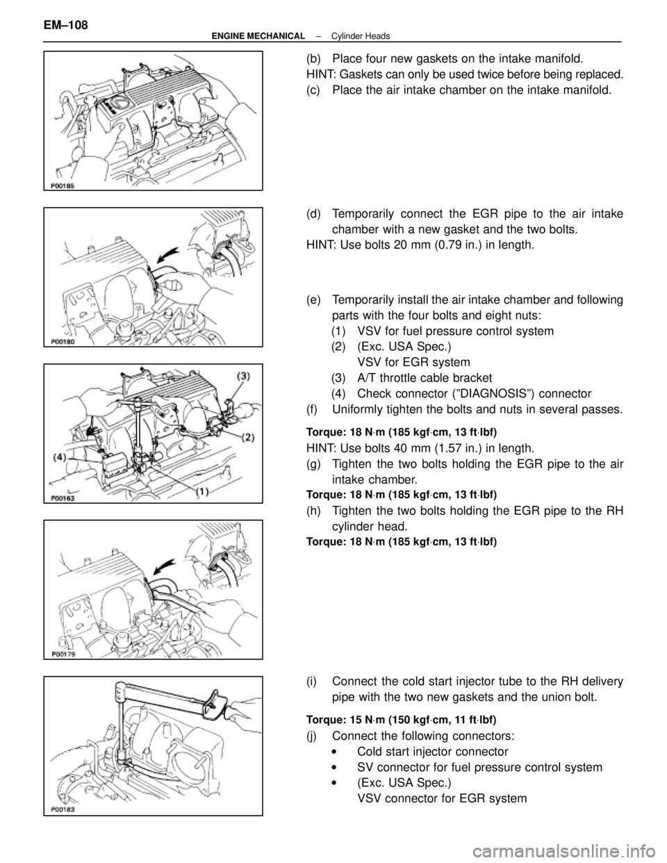
(b) Place four new gaskets on the intake manifold.
HINT: Gaskets can only be used twice before being replaced.
(c) Place the air intake chamber on the intake manifold.
(d) Temporarily connect the EGR pipe to the air intakechamber with a new gasket and the two bolts.
HINT: Use bolts 20 mm (0.79 in.) in length.
(e) Temporarily install the air intake chamber and following
parts with the four bolts and eight nuts:
(1) VSV for fuel pressure control system
(2) (Exc. USA Spec.) VSV for EGR system
(3) A/T throttle cable bracket
(4) Check connector (ºDIAGNOSISº) connector
(f) Uniformly tighten the bolts and nuts in several passes.
Torque: 18 N Vm (185 kgf Vcm, 13 ft Vlbf)
HINT: Use bolts 40 mm (1.57 in.) in length.
(g) Tighten the two bolts holding the EGR pipe to the air
intake chamber.
Torque: 18 N Vm (185 kgf Vcm, 13 ft Vlbf)
(h) Tighten the two bolts holding the EGR pipe to the RH
cylinder head.
Torque: 18 N Vm (185 kgf Vcm, 13 ft Vlbf)
(i) Connect the cold start injector tube to the RH delivery
pipe with the two new gaskets and the union bolt.
Torque: 15 N Vm (150 kgf Vcm, 11 ft Vlbf)
(j) Connect the following connectors:
w Cold start injector connector
w SV connector for fuel pressure control system
w (Exc. USA Spec.)
VSV connector for EGR system
EM±108
±
ENGINE MECHANICAL Cylinder Heads
WhereEverybodyKnowsYourName
Page 1816 of 4087
47. INSTALL PS PUMP(a) In sta ll th e PS pu mp with th e th re e bo lts an d nu t.Alternately tighten the bolts and nut.
Torque:
Bolt 39 N Vm (400 kgf Vcm, 29 ft Vlbf)
Nut 43 N Vm (440 kgf Vcm, 32 ft Vlbf)
(b) Connect the vacuum hose to the vacuum pipe.
48. INSTALL HYDRAULIC PUMP AND CAMSHAFT TIMING PULLEYS
(See steps 8, 10 and 11 on pages EM±48 to 49)
49. INSTALL HYDRAULIC PUMP AND CAMSHAFT TIMING PULLEYS
(See steps 12 to 43 on pages EM±49 to 57)
50. PERFORM ROAD TEST Check for abnormal noise, shock, slippage, correct shift
points and smooth operation.
±
ENGINE MECHANICAL Cylinder HeadsEM±115
WhereEverybodyKnowsYourName
Page 1822 of 4087
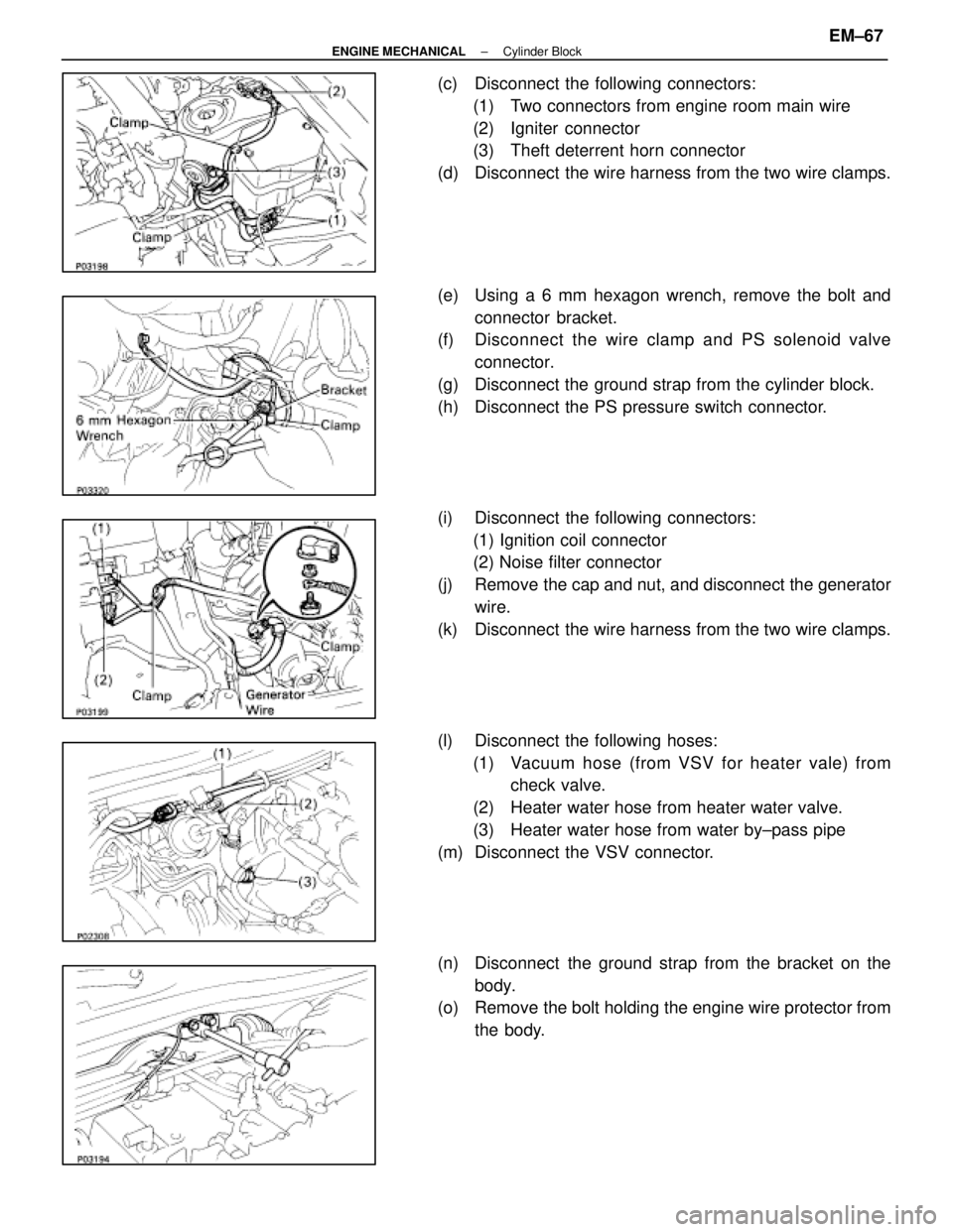
(c) Disconnect the following connectors:(1) Two connectors from engine room main wire
(2) Igniter connector
(3) Theft deterrent horn connector
(d) Disconnect the wire harness from the two wire clamps.
(e) Using a 6 mm hexagon wrench, remove the bolt and connector bracket.
(f) Disc onnect the wire clamp and PS solenoid valve
connector.
(g) Disconnect the ground strap from the cylinder block.
(h) Disconnect the PS pressure switch connector.
(i) Disconnect the following connectors: (1) Ignition coil connector
(2) Noise filter connector
(j) Remove the cap and nut, and disconnect the generator wire.
(k) Disconnect the wire harness from the two wire clamps.
(l) Disconnect the following hoses: (1) Vacuum hose (from VSV for heater vale) from check valve.
(2) Heater water hose from heater water valve.
(3) Heater water hose from water by±pass pipe
(m) Disconnect the VSV connector.
(n) Disconnect the ground strap from the bracket on the body.
(o) Remove the bolt holding the engine wire protector from
the body.
±
ENGINE MECHANICAL Cylinder BlockEM±67
WhereEverybodyKnowsYourName
Page 1832 of 4087
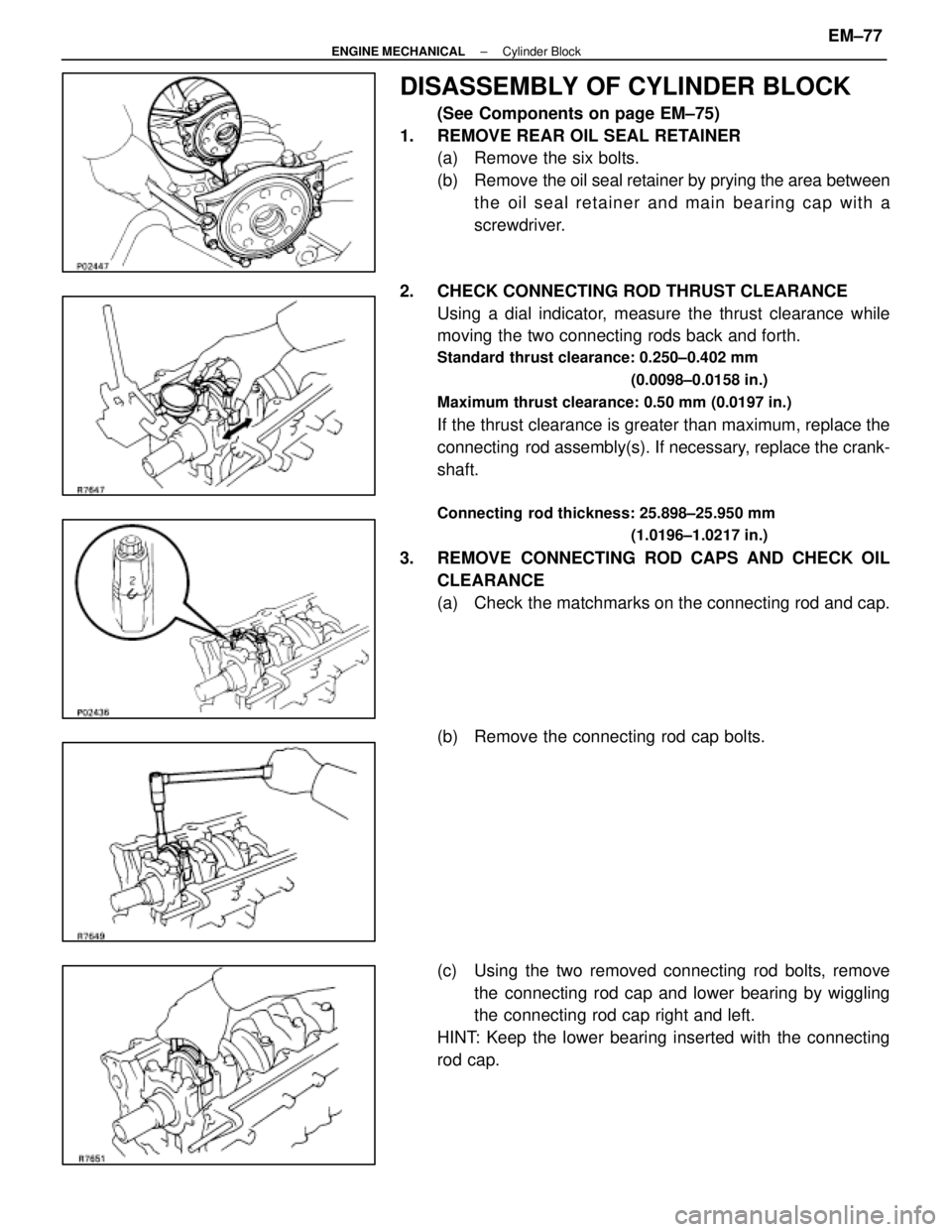
DISASSEMBLY OF CYLINDER BLOCK
(See Components on page EM±75)
1. REMOVE REAR OIL SEAL RETAINER (a) Remove the six bolts.
(b) Remove the oil seal retainer by prying the area between
the oil seal retainer and main bearing cap with a
screwdriver.
2. CHECK CONNECTING ROD THRUST CLEARANCE Using a dial indicator, measure the thrust clearance while
moving the two connecting rods back and forth.
Standard thrust clearance: 0.250±0.402 mm
(0.0098±0.0158 in.)
Maximum thrust clearance: 0.50 mm (0.0197 in.)
If the thrust clearance is greater than maximum, replace the
connecting rod assembly(s). If necessary, replace the crank-
shaft.
Connecting rod thickness: 25.898±25.950 mm (1.0196±1.0217 in.)
3. REMOVE CONNECTING ROD CAPS AND CHECK OILCLEARANCE
(a) Check the matchmarks on the connecting rod and cap.
(b) Remove the connecting rod cap bolts.
(c) Using the two removed connecting rod bolts, removethe connecting rod cap and lower bearing by wiggling
the connecting rod cap right and left.
HINT: Keep the lower bearing inserted with the connecting
rod cap.
±
ENGINE MECHANICAL Cylinder BlockEM±77
WhereEverybodyKnowsYourName
Page 1835 of 4087
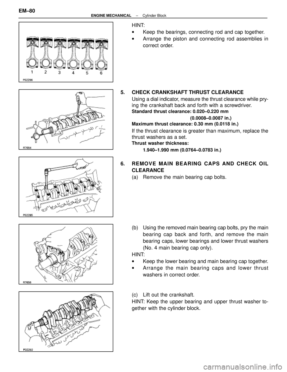
HINT:
wKeep the bearings, connecting rod and cap together.
w Arrange the piston and connecting rod assemblies in
correct order.
5. CHECK CRANKSHAFT THRUST CLEARANCE Using a dial indi cator, measure the thrust clearance while pry-
ing the crankshaft back and forth with a screwdriver.
Standard thrust clearance: 0.020±0.220 mm
(0.0008±0.0087 in.)
Maximum thrust clearance: 0.30 mm (0.0118 in.)
If the thrust clearance is greater than maximum, replace the
thrust washers as a set.
Thrust washer thickness:
1.940±1.990 mm (0.0764±0.0783 in.)
6. REMOVE MAIN BEARING CAPS AND CHECK OILCLEARANCE
(a) Remove the main bearing cap bolts.
(b) Using the removed main bearing cap bolts, pry the main
bearing cap back and forth, and remove the main
bearing caps, lower bearings and lower thrust washers
(No. 4 main bearing cap only).
HINT:
w Keep the lower bearing and main bearing cap together.
w Arrange the main bearing caps and lower thrust
washers in correct order.
(c) Lift out the crankshaft.
HINT: Keep the upper bearing and upper thrust washer to-
gether with the cylinder block.
EM±80
±
ENGINE MECHANICAL Cylinder Block
WhereEverybodyKnowsYourName
Page 1836 of 4087
(d) Clean each main journal and bearing.
(e) Check each main journal and bearing for pitting andscratches.
If the journal or bearing is damaged, replace the bearings.
If necessary, grind or replace the crankshaft.
(f) Place the crankshaft on the cylinder block.
(g) Lay a strip of Plastigage across each journal.
(h) Install the main bearing caps.
(See step 4 on pages EM±97 and 98)
Torque: 1st 44 N Vm (450 kgf Vcm, 33 ft Vlbf)
2nd turn 90 5
HINT: Do not turn the crankshaft.
(i) Remove the main bearing caps.
(See procedures (a) and (b) above)
(j) Measure the Plastigage at its widest point.
Standard clearance:
STD size 0.026±0.040 mm (0.0010±0.0016 in.)
U/S 0.25 0.025±0.061 mm (0.0010±0.0024 in.)
Maximum clearance: STD size 0.06 mm (0.0024 in.)
U/S 0.25 0.08 mm (0.0031 in.)
If the oil clearance is greater than maximum, replace the bearings.
If necessary, replace the crankshaft.
±
ENGINE MECHANICAL Cylinder BlockEM±81
WhereEverybodyKnowsYourName
Page 1839 of 4087
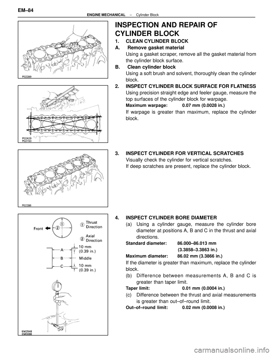
INSPECTION AND REPAIR OF
CYLINDER BLOCK
1. CLEAN CYLINDER BLOCK
A. Remove gasket materialUsing a gasket scraper, remove all the gasket material from
the cylinder block surface.
B. Clean cylinder block Using a soft brush and solvent, thoroughly clean the cylinder
block.
2. INSPECT CYLINDER BLOCK SURFACE FOR FLATNESS Using precision straight edge and feeler gauge, measure the
top surfaces of the cylinder block for warpage.
Maximum warpage: 0.07 mm (0.0028 in.)
If warpage is greater than maximum, replace the cylinder
block.
3. INSPECT CYLINDER FOR VERTICAL SCRATCHES Visually check the cylinder for vertical scratches.
If deep scratches are present, replace the cylinder block.
4. INSPECT CYLINDER BORE DIAMETER (a) Using a cylinder gauge, measure the cylinder borediameter at positions A, B and C in the thrust and axial
directions.
Standard diameter: 86.000±86.013 mm
(3.3858±3.3863 in.)
Maximum diameter: 86.02 mm (3.3866 in.)
If the diameter is greater than maximum, replace the cylinder
block.
(b) Difference between measurements A, B and C is greater than taper limit.
Taper limit: 0.01 mm (0.0004 in.)
(c) Difference between the thrust and axial measurementsis greater than out±of±round limit.
Out±of±round limit: 0.02 mm (0.0008 in.)
EM±84±
ENGINE MECHANICAL Cylinder Block
WhereEverybodyKnowsYourName