Page 1746 of 4087

Exhaust 44.250±44.350 mm (1.7421±1.7461 in.)
Maximum c")
B. Inspect cam lobesUsing a micrometer, measure the cam lobe height.
Standard cam lobe height:
Intake 44.570±44.670 mm (1.7547±1.7587 in.)
Exhaust 44.250±44.350 mm (1.7421±1.7461 in.)
Maximum cam lobe height: Intake 44.42 mm (1.7488 in.)
Exhaust 44.10 mm (1.7362 in.)
If the cam lobe height is less than minimum, replace the cam-
shaft.
C. Inspect camshaft journals Using a micrometer, measure the journal diameter.
Journal diameter: 28.949±28.965 mm
(1.1397±1.1404 in.)
If the journal diameter is not as specified, check the oil clear-
ance.
D. Inspect camshaft bearings Check the bearings for flaking and scoring.
If the bearings are damaged, replace the bearing caps and
cylinder head as a set.
E. Inspect camshaft journal oil clearance (a) Clean the bearing caps and camshaft journals.
(b) Place the camshafts on the cylinder head.
(c) Lay a strip of Plastigage across each of the camshaftjournals.
(d) Install the bearing caps. (See step 2 on page EM±55)
Torque: 20 N Vm (200 kgf Vcm, 14 ft Vlbf)
HINT: Do not turn the camshaft.
±
ENGINE MECHANICAL Cylinder HeadEM±49
WhereEverybodyKnowsYourName
Page 1751 of 4087
 Using a plastic±faced hammer, lightly tap the valve stem
tip to assure proper fit.
4. INSTALL VALVE LIFTERS AND SHIMS (a) Install the valve lifter and shim.
(b) Check that the valve lifter r")
(d) Using a plastic±faced hammer, lightly tap the valve stem
tip to assure proper fit.
4. INSTALL VALVE LIFTERS AND SHIMS (a) Install the valve lifter and shim.
(b) Check that the valve lifter rotates smoothly by hand.
INSTALLATION OF CYLINDER HEAD
(See Components on pages EM±34 and 35)1. INSTALL CYLINDER HEAD
A. Place cylinder head on cylinder block (a) Place a new cylinder head gasket in position on thecylinder block.
NOTICE: Be sure to install it correctly.
(b) Place the cylinder head in position on the cylinder head
gasket and connect the heater water hose to the union.
B. Install cylinder head bolts
HINT:
wThe cylinder head bolts are tightened in two progressive
steps (steps (c) and (f)).
w If any of bolts break or deform, replace them.
(a) Apply a light coat of engine oil on the threads and under
the heads of the cylinder head bolts.
(b) Install the 14 plate washers to each cylinder head bolt.
(c) First, using a 10 mm bi±hexagon wrench, uniformly tighten the cylinder head bolts in several passes in the
sequence shown.
Torque: 34 N Vm (350 kgf Vcm, 25 ft Vlbf)
If any one of the bolts does not meet the torque specification,
replace the bolt.
EM±54
±
ENGINE MECHANICAL Cylinder Head
WhereEverybodyKnowsYourName
Page 1752 of 4087
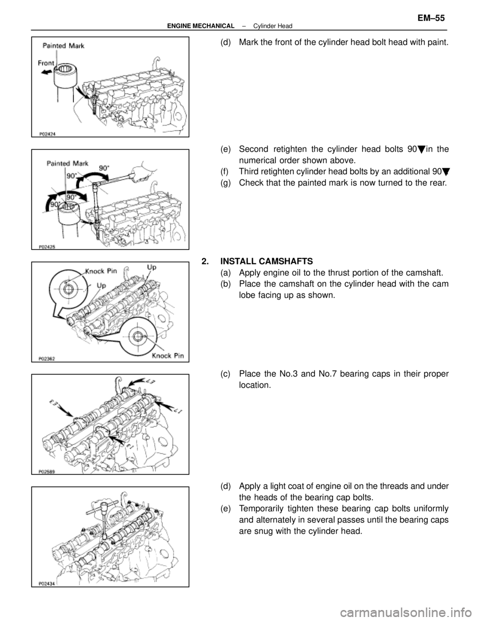
(d) Mark the front of the cylinder head bolt head with paint.
(e) Second retighten the cylinder head bolts 90� in the
numerical order shown above.
(f) Third retighten cylinder head bolts by an additional 90 �.
(g) Check that the painted mark is now turned to the rear.
2. INSTALL CAMSHAFTS (a) Apply engine oil to the thrust portion of the camshaft.
(b) Place the camshaft on the cylinder head with the camlobe facing up as shown.
(c) Place the No.3 and No.7 bearing caps in their proper location.
(d) Apply a light coat of engine oil on the threads and under
the heads of the bearing cap bolts.
(e) Temporarily tighten these bearing cap bolts uniformly
and alternately in several passes until the bearing caps
are snug with the cylinder head.
±
ENGINE MECHANICAL Cylinder HeadEM±55
WhereEverybodyKnowsYourName
Page 1754 of 4087
 Using SST, push the oil seal as far as it would go.
SST 09316±60010 (09316±00010, 09316±00050)
(n) Rotate the camshaft with a wrench at the hexagonposition, bring the forward straight pin u")
(m) Using SST, push the oil seal as far as it would go.
SST 09316±60010 (09316±00010, 09316±00050)
(n) Rotate the camshaft with a wrench at the hexagonposition, bring the forward straight pin up.
(o) Loosen the two bearing cap bolts as shown, until they
can be turned by hand; retighten in several passes.
Torque: 20 N Vm (200 kgf Vcm, 14 ft Vlbf)
(p) Turn the camshaft 1/3 of revolution.
(q) Loosen the two bearing cap bolts as shown, until they
can be turned by hand; retighten in several passes.
Torque: 20 N Vm (200 kgf Vcm, 14 ft Vlbf)
(r) Turn the camshaft a further 1/3 of a revolution.
(s) Loosen the two bearing cap bolts as shown, until they
can be turned by hand; retighten is several passes.
Torque: 20 N Vm (200 kgf Vcm, 14 ft Vlbf)
3. CHECK AND ADJUST VALVE CLEARANCE
(See steps 12 and 13 on pages EM±12 to 16)
Turn the camshaft, and position the cam lobe upward, check
and adjust the valve clearance.
Valve clearance:
Intake 0.15±0.25 mm (0.006±0.010 in.)
Exhaust 0.25±0.35 mm (0.010±0.014 in.)
±
ENGINE MECHANICAL Cylinder HeadEM±57
WhereEverybodyKnowsYourName
Page 1756 of 4087
 Install the harness protector to the intake manifold withthe two bolts.
(b) Install the three clamp bolts and two nuts.
(c) Connect the following conn")
8. CONNECT ENGINE WIRE TO INTAKE MANIFOLD(a) Install the harness protector to the intake manifold withthe two bolts.
(b) Install the three clamp bolts and two nuts.
(c) Connect the following connectors:
(1) Engine coolant temperature sensor connector
(2) Engine coolant temperature sender gauge connec- tor
(3) Two knock sensor connectors
(4) Oil pressure switch connector
(5) Oil level sensor connector
(6) A/C compressor connector
9. INSTALL NO. 1 AND NO. 2 FUEL PIPES
Torque: 8.8 N Vm (90 kgf Vcm, 78 in. Vlbf)
10. INSTALL DELIVERY PIPE AND INJECTORS
(See steps 1, 3, 6 and 7 on pages FI±33 and 34)
Torque: 21 N Vm (210 kgf Vcm, 15 ft Vlbf)
11. INSTALL AIR INTAKE CHAMBER
(a) Install a new gasket and the intake chamber with the five
bolts and two nuts.
Torque: 21 N Vm (210 kgf Vcm, 15 ft Vlbf)
(b) Install the check connector and harness protector to the
air intake chamber with the two bolts.
(c) Connect the following hoses: (1) Vacuum hose to brake booster union
(2) Vacuum hose (to ACIS vacuum tank)
(3) Vacuum sensing hose
(4) Air hose (to PS air control valve)
±
ENGINE MECHANICAL Cylinder HeadEM±59
WhereEverybodyKnowsYourName
Page 1758 of 4087
 Install a new gasket and the exhaust manifold with thefour nuts. Install the No. 1 and No. 2 exhaust manifolds.
Torque: 39 N Vm (400 kgf Vcm, 29 ft Vlbf)
(b) Instal")
16. INSTALL EXHAUST MANIFOLD(a) Install a new gasket and the exhaust manifold with thefour nuts. Install the No. 1 and No. 2 exhaust manifolds.
Torque: 39 N Vm (400 kgf Vcm, 29 ft Vlbf)
(b) Install the manifold heat insulator with the four nuts.
Torque: 18 N Vm (185 kgf Vcm, 13 ft Vlbf)
(c) Connect the two oxygen sensor connectors.
17. INSTALL NO. 2 FRONT EXHAUST PIPE (See step 5 on page EM±105)
18. INSTALL TIMING BELT (See steps 8 to 14 on pages EM±30 to 33)
19. INSTALL RADIATOR AND WATER PUMP PULLEY (See steps 15, 16, 19 and 24 on pages EM±110 to 112)
20. INSTALL SPARK PLUGS (See step 6 on page IG±9)
Torque: 18 N Vm (180 kgf Vcm, 13 ft Vlbf)
21. CONNECT HIGH±TENSION CORDS TO SPARK PLUGS
(See steps 14 to 21 on pages EM±17 to 21)
22. FILL ENGINE WITH COOLANT (See page CO±5)
Capacity (w/ Heater): M/T 8.5 liters (9.0 US qts, 7.5 lmp. qts)
A/T 8.4 liters (8.9 US pts, 7.4 lmp. qts)
23. START ENGINE AND CHECK FOR LEAKS
24. (A/T)CHECK AUTOMATIC TRANSMISSION FLUID LEVEL
(See page MA±11)
NOTICE: Do not overfill.
25. CHECK IGNITION TIMING (See page IG±14)
Ignition timing: 105 BTDC @ idle
(w/ Terminals TE1 and E1 connected)
26. PERFORM ROAD TEST Check for abnormal noise, shock, slippage, correct shift
points and smooth operation.
27. RECHECK ENGINE COOLANT LEVEL
±
ENGINE MECHANICAL Cylinder HeadEM±61
WhereEverybodyKnowsYourName
Page 1767 of 4087
(c) Remove the two bolts and gaskets, and disconnect theEGR pipe from the air intake chamber.
(d) Remove the four mounting bolts, eight mounting nuts and following parts:
(1) VSV for fuel pressure control system
(2) (Exc. USA Spec.)
VSV for EGR system
(3) A/T throttle cable bracket
(e) Disconnect the check (ºDIAGNOSISº) connector from
the intake chamber.
(f) Remove the air intake chamber and four gaskets.
(g) Remove the three bolts, the cold start injector, tube, lead
wire assembly and gasket.
21. DISCONNECT HEATER WATER HOSES Disconnect the following hoses:(1) Water hose from water by±pass pipe
(2) Water hose from rear water by±pass joint
22. DISCONNECT FUEL INLET HOSE FROM LH DELIVERY PIPE
Remove the pulsation damper and two gaskets, and discon-
nect the inlet hose.
23. D I S C O N N E C T F U E L R E T U R N H O S E F R O M F U E L RETURN PIPE
EM±66
±
ENGINE MECHANICAL Cylinder Heads
WhereEverybodyKnowsYourName
Page 1780 of 4087
D. Clean cylinder headsUsing a soft brush and solvent, thoroughly clean the cylinder
heads.
3. INSPECT CYLINDER HEADS
A. Inspect for flatness Using a precision straight edge and feeler gauge, measure
the surfaces contacting the cylinder block and manifolds for
warpage.
Maximum warpage: 0.10 mm (0.0039 in.)
If warpage is greater than maximum, replace the cylinder
head.
B. Inspect for cracks Using a dye penetrant, check the combustion chamber, in-
take ports, exhaust ports and cylinder block surface for
cracks.
If cracked, replace the cylinder head.
4. CLEAN VALVES (a) Using a gasket scraper, chip any carbon from the valvehead.
(b) Using a wire brush, thoroughly clean the valve.
±
ENGINE MECHANICAL Cylinder HeadsEM±79
WhereEverybodyKnowsYourName
 Remove the two bolts and gaskets, and disconnect theEGR pipe from the air intake chamber.
(d) Remove the four mounting bolts, eight mounting nuts and following parts:
(1) VSV for fuel pressure")
