Page 1864 of 4087

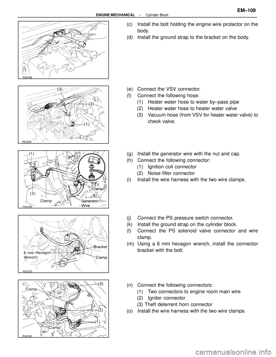
(c) Install the bolt holding the engine wire protector on thebody.
(d) Install the ground strap to the bracket on the body.
(e) Connect the VSV connector.
(f) Connect the following hose: (1) Heater water hose to water by±pass pipe
(2) Heater water hose to heater water valve
(3) Vacuum hose (from VSV for heater water valve) to
check valve.
(g) Install the generator wire with the nut and cap.
(h) Connect the following connector: (1) Ignition coil connector
(2) Noise filter connector
(i) Install the wire harness with the two wire clamps.
(j) Connect the PS pressure switch connector.
(k) Install the ground strap on the cylinder block.
(l) Connect the PS solenoid valve connector and wire
clamp.
(m) Using a 6 mm hexagon wrench, install the connector bracket with the bolt.
(n) Connect the following connectors: (1) Two connectors to engine room main wire
(2) Igniter connector
(3) Theft deterrent horn connector
(o) Install the wire harness with the two wire clamps.
±
ENGINE MECHANICAL Cylinder BlockEM±109
WhereEverybodyKnowsYourName
Page 1867 of 4087

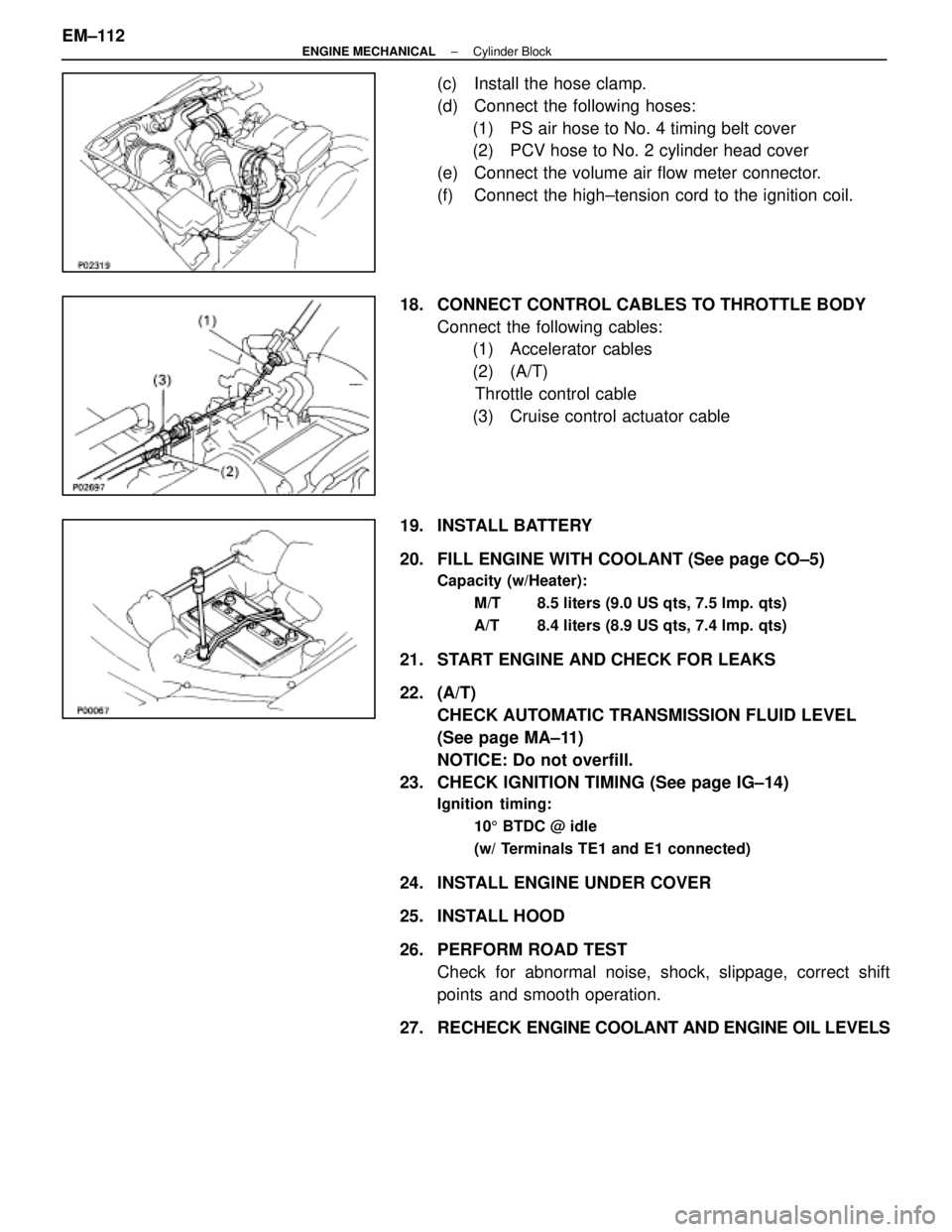
(c) Install the hose clamp.
(d) Connect the following hoses:(1) PS air hose to No. 4 timing belt cover
(2) PCV hose to No. 2 cylinder head cover
(e) Connect the volume air flow meter connector.
(f) Connect the high±tension cord to the ignition coil.
18. CONNECT CONTROL CABLES TO THROTTLE BODY Connect the following cables:(1) Accelerator cables
(2) (A/T)
Throttle control cable
(3) Cruise control actuator cable
19. INSTALL BATTERY
20. FILL ENGINE WITH COOLANT (See page CO±5)
Capacity (w/Heater): M/T 8.5 liters (9.0 US qts, 7.5 lmp. qts)
A/T 8.4 liters (8.9 US qts, 7.4 lmp. qts)
21. START ENGINE AND CHECK FOR LEAKS
22. (A/T)CHECK AUTOMATIC TRANSMISSION FLUID LEVEL
(See page MA±11)
NOTICE: Do not overfill.
23. CHECK IGNITION TIMING (See page IG±14)
Ignition timing:
105 BTDC @ idle
(w/ Terminals TE1 and E1 connected)
24. INSTALL ENGINE UNDER COVER
25. INSTALL HOOD
26. PERFORM ROAD TEST Check for abnormal noise, shock, slippage, correct shift
points and smooth operation.
27. RECHECK ENGINE COOLANT AND ENGINE OIL LEVELS
EM±112
±
ENGINE MECHANICAL Cylinder Block
WhereEverybodyKnowsYourName
Page 1880 of 4087

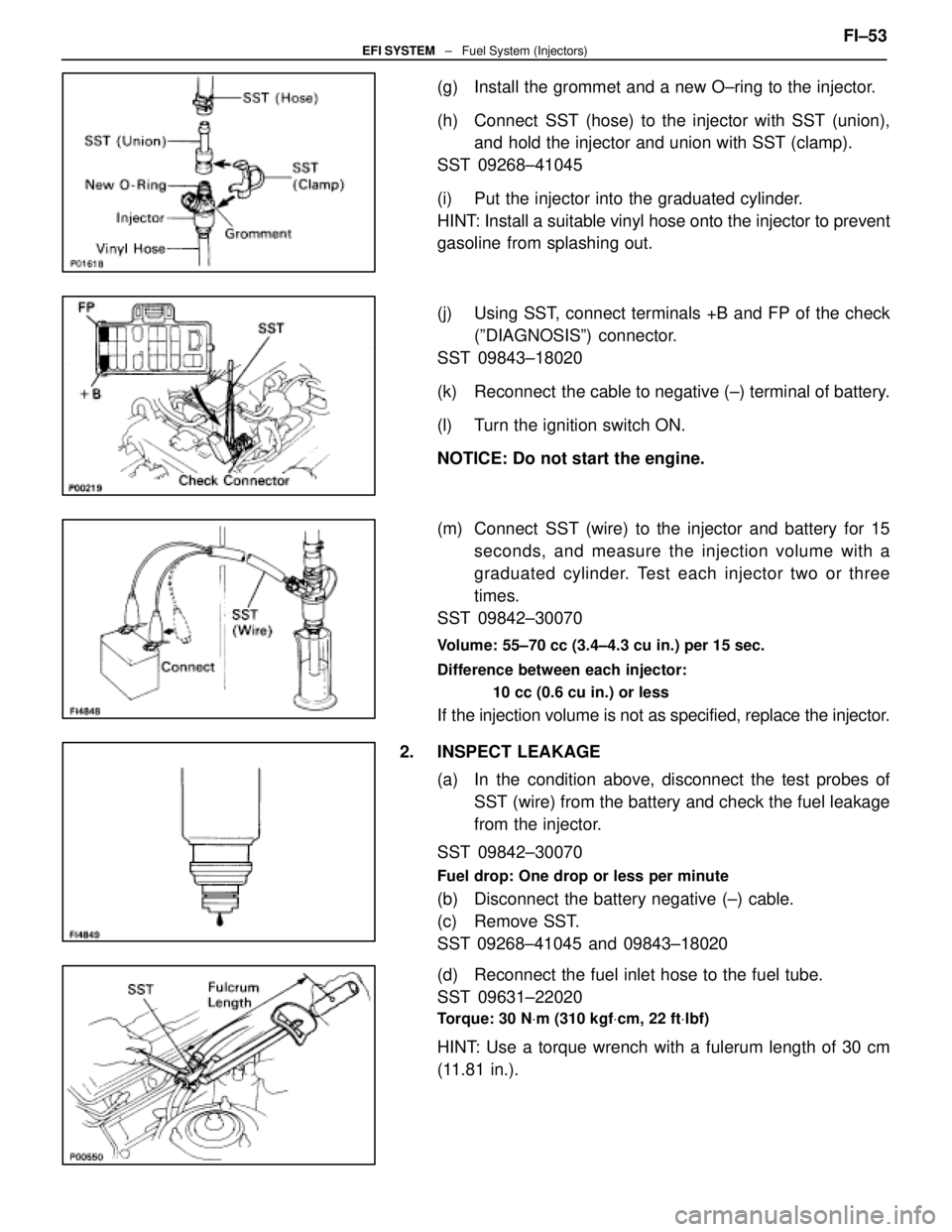
(g) Install the grommet and a new O±ring to the injector.
(h) Connect SST (hose) to the injector with SST (union),and hold the injector and union with SST (clamp).
SST 09268±41045
(i) Put the injector into the graduated cylinder.
HINT: Install a suitable vinyl hose onto the injector to prevent
gasoline from splashing out.
(j) Using SST, connect terminals +B and FP of the check (ºDIAGNOSISº) connector.
SST 09843±18020
(k) Reconnect the cable to negative (±) terminal of battery.
(l) Turn the ignition switch ON.
NOTICE: Do not start the engine.
(m) Connect SST (wire) to the injector and battery for 15 seconds, and measure the injection volume with a
graduated cylinder. Test each injector two or three
times.
SST 09842±30070
Volume: 55±70 cc (3.4±4.3 cu in.) per 15 sec.
Difference between each injector:
10 cc (0.6 cu in.) or less
If the injection volume is not as specified, replace the injector.
2. INSPECT LEAKAGE (a) In the condition above, disconnect the test probes ofSST (wire) from the battery and check the fuel leakage
from the injector.
SST 09842±30070
Fuel drop: One drop or less per minute
(b) Disconnect the battery negative (±) cable.
(c) Remove SST.
SST 09268±41045 and 09843±18020
(d) Reconnect the fuel inlet hose to the fuel tube.
SST 09631±22020
Torque: 30 N Vm (310 kgf Vcm, 22 ft Vlbf)
HINT: Use a torque wrench with a fulerum length of 30 cm
(11.81 in.). FI±53
EFI SYSTEM
± Fuel System (Injectors)
WhereEverybodyKnowsYourName
Page 1885 of 4087
Idle Speed Control (ISC) Valve
ON±VEHICLE INSPECTION
INSPECT ISC VALVE FOR OPERATING SOUNDCheck that there is a clicking sound immediately after stop-
ping the engine.
If the rpm operation is not as specified, check the ISC valve,
wiring and ECU.
±
EFI SYSTEM Air Induction System (Idle Speed Control (ISC) Valve)FI±53
WhereEverybodyKnowsYourName
Page 1888 of 4087
Acoustic Control Induction System (ACIS)
ON±VEHICLE INSPECTION
INSPECT IACV(a) Using a 3±way connector, connect vacuum gauge to the
actuator hose.
(b) Start the engine.
(c) While the engine is idling, check that the vacuum gauge needle does not move.
(d) Repidly depress the accelerator pedal to fully open position and check that the vacuum gauge needle
momentarily fluctuates approx. 53.3 kPa (400 mmHg,
15.75 in.Hg). (The actuator rod is pulled out.)
FI±56
±
EFI SYSTEM Air Induction System (Acoustic Control Induction System (ACIS)
WhereEverybodyKnowsYourName
Page 1897 of 4087

INSTALLATION OF FUEL PRESSURE
PULSATION DAMPER
(See Components on page FI±58)
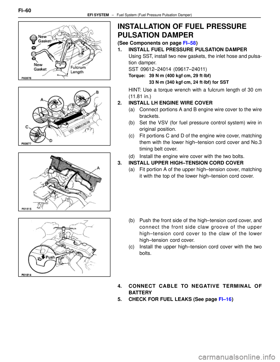
1. INSTALL FUEL PRESSURE PULSATION DAMPER Using SST, install two new gaskets, the inlet hose and pulsa-
tion damper.
SST 09612±24014 (09617±24011)
Torque: 39 N Vm (400 kgf Vcm, 29 ft Vlbf)
33 N Vm (340 kgf Vcm, 24 ft Vlbf) for SST
HINT: Use a torque wrench with a fulcrum length of 30 cm
(11.81 in.)
2. INSTALL LH ENGINE WIRE COVER
(a) Connect portions A and B engine wire cover to the wirebrackets.
(b) Set the VSV (for fuel pressure control system) wire in original position.
(c) Fit portions C and D of the engine wire cover, matching them with the lower high±tension cord cover and No.3
timing belt cover.
(d) Install the engine wire cover with the two bolts.
3. INSTALL UPPER HIGH±TENSION CORD COVER (a) Fit portion A of the upper high±tension cover, matching
it with the top of the lower high±tension cord cover.
(b) Push the front side of the high±tension cord cover, and connect the front side claw groove of the upper
high±tension cord cover to the claw of the lower
high±tension cord cover.
(c) Install the upper high±tension cord cover with the two bolts.
4. CONNECT CABLE TO NEGATIVE TERMINAL OF BATTERY
5. CHECK FOR FUEL LEAKS (See page FI±16)
FI±60
EFI SYSTEM
± Fuel System (Fuel Pressure Pulsation Damper)
WhereEverybodyKnowsYourName
Page 1903 of 4087
EFI Main Relay
INSPECTION OF EFI MAIN RELAY
1. REMOVE EFI MAIN RELAY FROM RELAY BOX IN ENGINE
COMPARTMENT
2. INSPECT EFI MAIN RELAY
A. Inspect relay continuity (a) Using an ohmmeter, check that there is continuitybetween terminals 1 and 3.
(b) Check that there is no continuity between terminals 2 and 4.
If continuity is not as specified, replace the relay.
B. Inspect relay operation (a) Apply battery voltage across terminals 1 and 3.
(b) Using an ohmmeter, check that there is continuitybetween terminals 2 and 4.
If operation is not as specified, replace the relay.
3. REINSTALL EFI MAIN RELAY
FI±64
±
EFI SYSTEM Electronic Control System (EFI main RelaY)
WhereEverybodyKnowsYourName
Page 1906 of 4087
ON±VEHICLE INSPECTION
1. INSPECT THROTTLE BODY(a) Remove the throttle body cover.w Remove the mounting cap nut.
w Loosen the two bolts, and remove the throttle body
cover.
(b) Check that the throttle linkage moves smoothly.
(c) Check the vacuum at each port. w Start the engine.
w Check the vacuum with your finger.
Port nameAt idlingAt 3,000 rpm
PNo vacuumVacuum
*ENo vacuumVacuum
*RNo vacuumVacuum
* Exc. USA Spec.
(d) Reinstall the throttle body cover.
3. INSPECT AND ADJUST DASH POT (DP)
A. Warm up engine Allow the engine to warm up to normal operating tempera-
ture.
B. Check idle speed
Idle speed: 700 + 50 rpm
C. Remove cap, filter and separator from DP FI±67
EFI SYSTEM
± Air Induction System (Throttle Body)
WhereEverybodyKnowsYourName