Page 1990 of 4087
B. Inspect resistance of engine & ECT ECU wiring connectorsNOTICE: Do not touch the ECU terminals.
Check the resistance between each terminal of the wiring
connectors.w Disconnect the SST (check harness) connectors
from the ECU.
w Measure the resistance at each terminal.
FI±133EFI SYSTEM ± Electronic Control System (Engine & ECT ECU)
WhereEverybodyKnowsYourName
Page 1993 of 4087
Fuel Cut RPM
INSPECTION OF FUEL CUT RPM
1. WARM UP ENGINEAllow the engine to warm up to normal operating
temperature.
2. CONNECT TACHOMETER Connect the test probe of a tachometer to terminal IG of the
check connector.
NOTICE
w Never allow the tachometer terminal to touch ground as
it could result in damage to the igniter and/or ignition
coil.
w As some tachometers are not compatible with this
ignition system, we recommend that you confirm the
compatibility of yours before use.
3. INSPECT FUEL CUT OPERATION
(a) Increase the engine speed to at least 2,500 rpm.
(b) Check for injector operating noise.
(c) Check that when the throttle lever is released, injectoroperation noise stops momentarily and then resumes.
HINT:
w The vehicle should be stopped.
w Measure with the A/C OFF.
Fuel return rpm: 1,400 rpm
4. REMOVE TACHOMETER
FI±136
± Electronic Control System (Fuel \
Cut RPM)EFI SYSTEM
WhereEverybodyKnowsYourName
Page 2003 of 4087

The EFI system is composed of three basic sub±systems: Fuel, Air Induction and Elect\
ronic Control
Systems.
FUEL SYSTEM
An electric pump fuel pressure supplies sufficient fuel, under a constant pressure, to the EFI injectors. In
accordance with signals from the ECU (Electronic Control Unit), these \
injectors inject the quantity of fuel most
appropriate for the engine condition into the intake manifold.
AIR INDUCTION SYSTEM
The air induction system provides sufficient air for engine operation.
ELECTRONIC CONTROL SYSTEM
The 1UZ±FE engine (ECU±formerly EFI computer) with a microcomputer \
centrally controls the EFI, ESA,
ISC and Diagnosis system, etc. The ECU controls the following functions:
1. Electronic Fuel Injection (EFI)
The ECU receives signals from various sensors indicating changing engine op\
eration conditions such as:Intake air volume
Intake air temperature
Coolant temperature
Engine rpm
Acceleration/deceleration
Exhaust oxygen content etc.
The signals are utilized by the ECU to determine the injection duration nec\
essary for an optimum air±fuel
ratio.
2. Electronic Spark Advance (ESA) The ECU is programmed with data for optimum ignition timing under any and all opera\
ting conditions. Using
data provided by sensors which monitor various engine functions (rpm, coola\
nt temperature, etc.), the
Electronic Control Unit (ECU) triggers the spark at precisely right instant. (S\
ee IG section)
3. Idle Speed Control (ISC) The ECU is programmed with idle speed data for various engine conditions (\
coolant temperature, air condi-
tioner ON/OFF, etc.).
The air volume flowing through the throttle valve by±pass passage is adj\
usted according to the signal from
each sensor and the idle speed is kept at the set value.
4. Diagnosis Function When the ECU detects any malfunctions or abnormalities in the sensor network\
, it lights the ºCHECKº en-
gine warning light in the combination meter. At the same time, the trouble is identified and a diagnostic code
is recorded by the ECU. The diagnostic code can be read by the number of\
blinks of the ºCHECKº engine
warning light when terminals TE1 and E1 are connected. The diagnostic co\
des are refer to the later page.
(See TR section)
5. Self±Correction Function If any sensor malfunctions, an average value recorded in the back±up ci\
rcuit is substituted to make driving
possible.
If danger is predicted, the engine is stopped and the ºCHECKº engine\
warning light will light up.
6. Fail±Safe Function Even if an abnormality occurs in the ECU, the back±up circuit uses a specifie\
d fuel injection and ignition
timing to provide vehicle driveability, and also lightsup the ºCHECKº engine warning light.
FI±4
EFI SYSTEM
± Description
WhereEverybodyKnowsYourName
Page 2014 of 4087
PREPARATION
SST (SPECIAL SERVICE TOOLS)
IllustrationPart No.Part NameNote
09268±41045Injection Measuring
Tool Set
(09268±41090)(No. 7 Union)
Injector
(09268±52010)(Injection Measuring
Attachment)
Injector
(09405±09015)(No. 1 Union)
Injector
09268±45012EFI Fuel Pressure
Gauge
09612±24014
Steering Gear
Housing Overhaul
Tool Set
(09617±24011(Steering Rack Wrench)
Fuel pressure pulsation damper
09631±22020
Power Steering
Hose Nut 14 x 17 mm
Wrench SetFuel line flare nut
09816±30010Oil Pressure
Switch Socket
Knock sensor
09842±30070Wire ªFº
EFI Inspection
Injector
09843±18020Diagnosis Check
Wire
09990±01000
Engine Control
Computer Check
Harness ªAº
±
EFI SYSTEM PreparationFI±9
WhereEverybodyKnowsYourName
Page 2016 of 4087
Preparation
SST (SPECIAL SERVICE TOOLS)
IllustrationPart No.Part NameNote
09268±41045Injection Measuring
Tool Set
(90268±41070)No. 4 Union
Injector
(09268±41080)No. 6 Union
Cold start Injector
(09268±52010)Injection Measuring
Attachment
Injector
09268±45012EFI Fuel Pressure
Gauge
09612±24014
Steering Gear
Housing Overhaul
Tool Set
(09617±24011)Steering Rack Wrench
Fuel pressure pulsation damper
09631±22020
Power Steering
Hose Nut 14 X 17 mm
Wrench SetFuel line flare nut
09816±30010Oil Pressure
Switch SocketKnock sensor
09842±30055Wire ªGº
EFI Inspection
Cold start Injector
09842±30070Wire ªFº
EFI Inspection
Injector
09843±18020Diagnosis Check
Wire
0990±01000
Engine Control
Computer
Check Harness ªAº
FI±10 ± PreparationEFI SYSTEM
WhereEverybodyKnowsYourName
Page 2018 of 4087

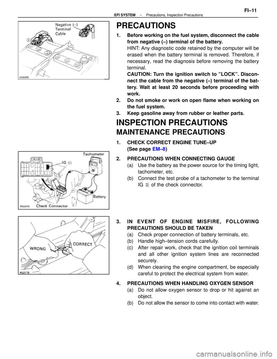
PRECAUTIONS
1. Before working on the fuel system, disconnect the cablefrom negative (±) terminal of the battery.
HINT: Any diagnostic code retained by the computer will be
erased when the battery terminal is removed. Therefore, if
necessary, read the diagnosis before removing the battery
terminal.
CAUTION: Turn the ignition switch to ºLOCKº. Discon-
nect the cable from the negative (±) terminal of the bat-
tery. Wait at least 20 seconds before proceeding with
work.
2. Do not smoke or work on open flame when working on the fuel system.
3. Keep gasoline away from rubber or leather parts.
INSPECTION PRECAUTIONS
MAINTENANCE PRECAUTIONS
1. CHECK CORRECT ENGINE TUNE±UP (See page EM±8)
2. PRECAUTIONS WHEN CONNECTING GAUGE (a) Use the battery as the power source for the timing light,tachometer, etc.
(b) Connect the test probe of a tachometer to the terminal IG � of the check connector.
3. IN EVENT OF ENGINE MISFIRE, FOLLOWING PRECAUTIONS SHOULD BE TAKEN
(a) Check proper connection of battery terminals, etc.
(b) Handle high±tension cords carefully.
(c) After repair work, check that the ignition coil terminalsand all other ignition system lines are reconnected
securely.
(d) When cleaning the engine compartment, be especially careful to protect the electrical system from water.
4. PRECAUTIONS WHEN HANDLING OXYGEN SENSOR (a) Do not allow oxygen sensor to drop or hit against anobject.
(b) Do not allow the sensor to come into contact with water.
±
EFI SYSTEM Precautions, Inspection PrecautionsFI±11
WhereEverybodyKnowsYourName
Page 2019 of 4087

IF VEHICLE IS EQUIPPED WITH MOBILE
RADIO SYSTEM (HAM, CB, ETC.)
The ECU has been designed so that it will not be affected by out-
side interference. However, if your vehicle is equipped with a CB
radio transceiver, etc. (even one with about 10 W output), it may,
at times, have an effect upon ECU operation, especially if the an-
tenna and feeder are installed nearby.
Therefore, observe the following precautions:
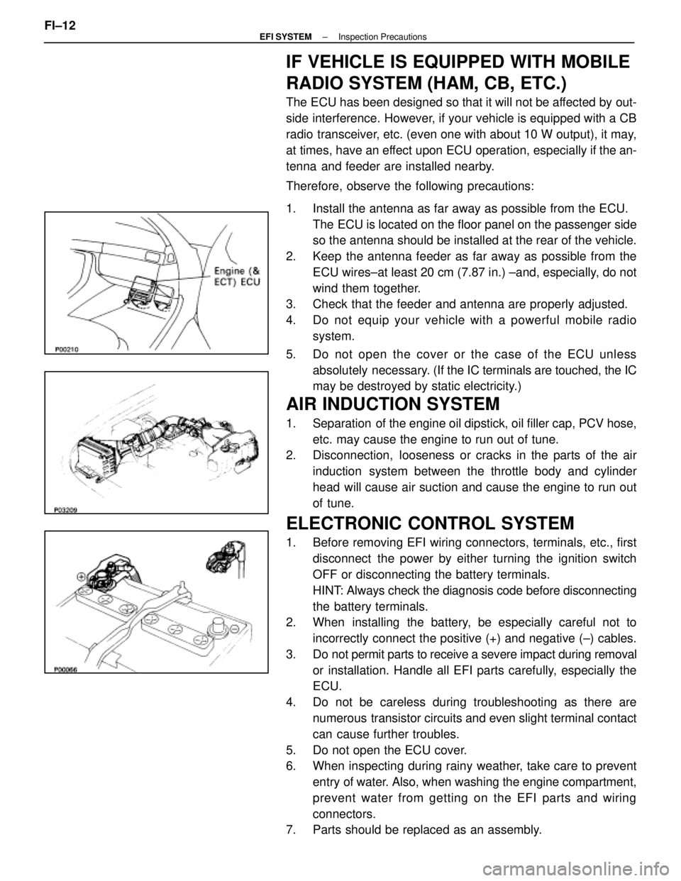
1. Install the antenna as far away as possible from the ECU. The ECU is located on the floor panel on the passenger side
so the antenna should be installed at the rear of the vehicle.
2. Keep the antenna feeder as far away as possible from the ECU wires±at least 20 cm (7.87 in.) ±and, especially, do not
wind them together.
3. Check that the feeder and antenna are properly adjusted.
4. Do not equip your vehicle with a powerful mobile radio
system.
5. Do not open the cover or the case of the ECU unless absolutely necessary. (If the IC terminals are touched, the IC
may be destroyed by static electricity.)
AIR INDUCTION SYSTEM
1. Separation of the engine oil dipstick, oil filler cap, PCV hose,
etc. may cause the engine to run out of tune.
2. Disconnection, looseness or cracks in the parts of the air
induction system between the throttle body and cylinder
head will cause air suction and cause the engine to run out
of tune.
ELECTRONIC CONTROL SYSTEM
1. Before removing EFI wiring connectors, terminals, etc., firstdisconnect the power by either turning the ignition switch
OFF or disconnecting the battery terminals.
HINT: Always check the diagnosis code before disconnecting
the battery terminals.
2. When installing the battery, be especially careful not to
incorrectly connect the positive (+) and negative (±) cables.
3. Do not permit parts to receive a severe impact during removal or installation. Handle all EFI parts carefully, especially the
ECU.
4. Do not be careless during troubleshooting as there are numerous transistor circuits and even slight terminal contact
can cause further troubles.
5. Do not open the ECU cover.
6. When inspecting during rainy weather, take care to prevent entry of water. Also, when washing the engine compartment,
prevent water from getting on the EFI parts and wiring
connectors.
7. Parts should be replaced as an assembly.
FI±12
±
EFI SYSTEM Inspection Precautions
WhereEverybodyKnowsYourName
Page 2022 of 4087
4. Install the injector to delivery pipe and cylinder head asshown in the illustration.
5. Check that there are no fuel leaks after performing any maintenance on the fuel system.
(a) Using SST, connect terminals +B and FP of the check(ºDIAGNOSISº) connector.
SST 09843±18020
(b) With engine stopped, turn the ignition switch ON.
(c) When the fuel return hose is pinched, the pressure within high pressure line will rise to approx. 392 kPa (4
kgf/cm2, 57 psi). In this state, check to see that there are
no leaks from any part of the fuel system.
NOTICE: Always pinch the hose. Avoid bending as it may
cause the hose to crack.
(d) Turn the ignition switch OFF.
(e) Remove SST from the check connector.
SST 09843±18020
±
EFI SYSTEM Inspection PrecautionsFI±15
WhereEverybodyKnowsYourName