Page 2037 of 4087
If there is no pressure, check the following parts:w Fuses
w EFI main relay
w Fuel pump ECU
w Fuel pump
w Engine & ECT ECU
w Wiring connections
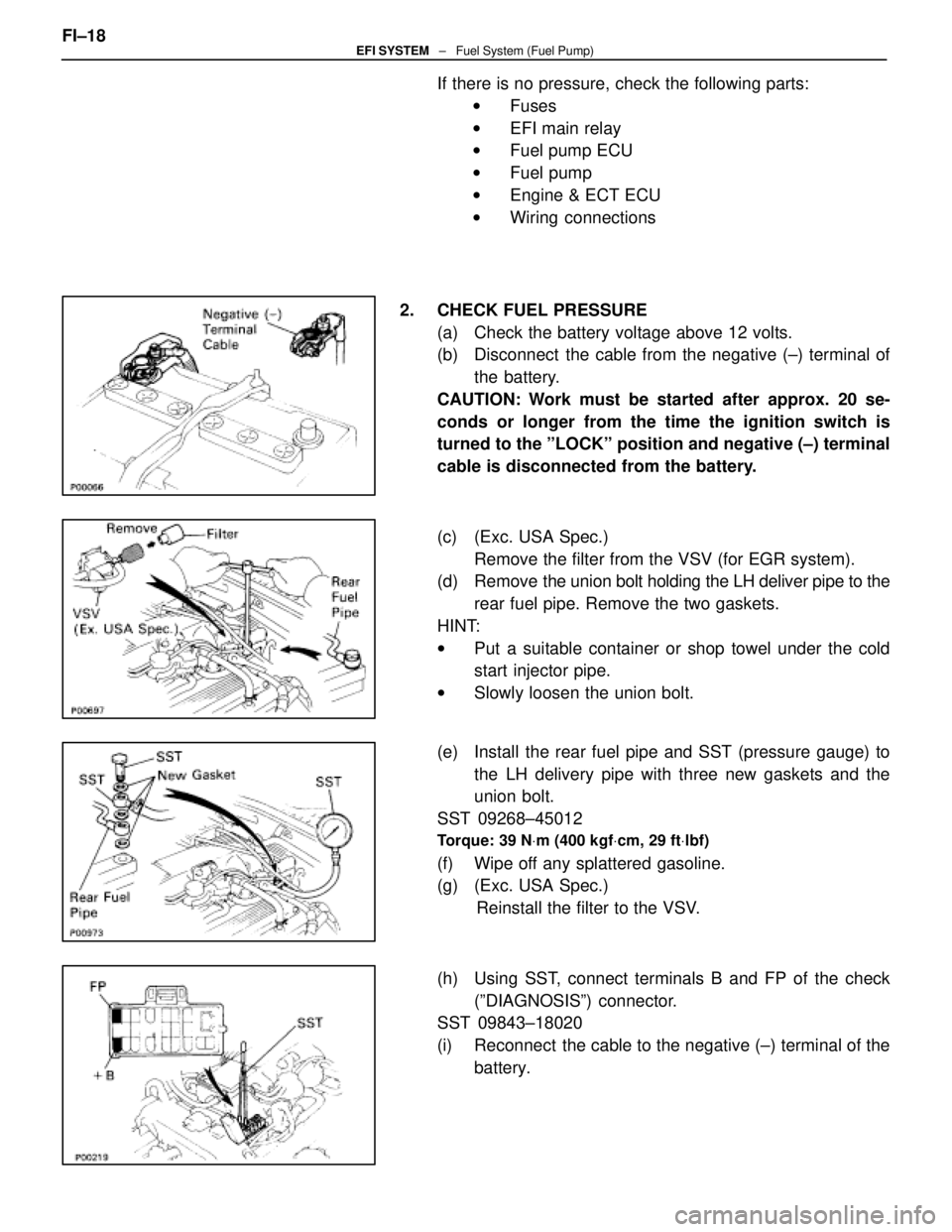
2. CHECK FUEL PRESSURE (a) Check the battery voltage above 12 volts.
(b) Disconnect the cable from the negative (±) terminal ofthe battery.
CAUTION: Work must be started after approx. 20 se-
conds or longer from the time the ignition switch is
turned to the ºLOCKº position and negative (±) terminal
cable is disconnected from the battery.
(c) (Exc. USA Spec.) Remove the filter from the VSV (for EGR system).
(d) Remove the union bolt holding the LH deliver pipe to the
rear fuel pipe. Remove the two gaskets.
HINT:
w Put a suitable container or shop towel under the cold
start injector pipe.
w Slowly loosen the union bolt.
(e) Install the rear fuel pipe and SST (pressure gauge) to the LH delivery pipe with three new gaskets and the
union bolt.
SST 09268±45012
Torque: 39 N Vm (400 kgf Vcm, 29 ft Vlbf)
(f) Wipe off any splattered gasoline.
(g) (Exc. USA Spec.)
Reinstall the filter to the VSV.
(h) Using SST, connect terminals B and FP of the check (ºDIAGNOSISº) connector.
SST 09843±18020
(i) Reconnect the cable to the negative (±) terminal of the
battery.
FI±18
EFI SYSTEM
± Fuel System (Fuel Pump)
WhereEverybodyKnowsYourName
Page 2038 of 4087
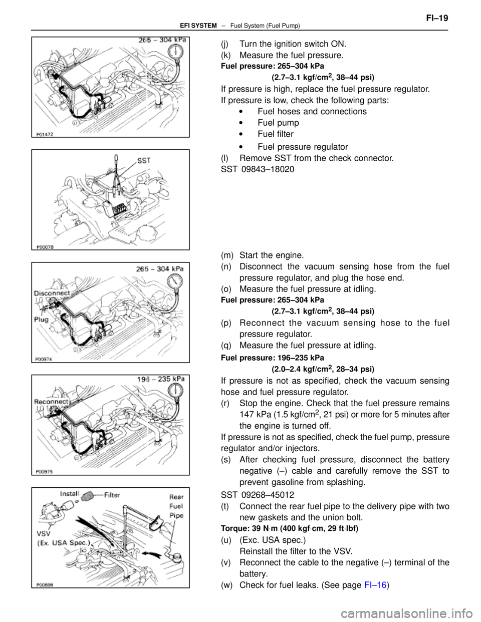
(j) Turn the ignition switch ON.
(k) Measure the fuel pressure.
Fuel pressure: 265±304 kPa(2.7±3.1 kgf/cm
2, 38±44 psi)
If pressure is high, replace the fuel pressure regulator.
If pressure is low, check the following parts:w Fuel hoses and connections
w Fuel pump
w Fuel filter
w Fuel pressure regulator
(l) Remove SST from the check connector.
SST 09843±18020
(m) Start the engine.
(n) Disconnect the vacuum sensing hose from the fuel pressure regulator, and plug the hose end.
(o) Measure the fuel pressure at idling.
Fuel pressure: 265±304 kPa
(2.7±3.1 kgf/cm
2, 38±44 psi)
(p) Re connect the vacuum sensing hose to the fuel
pressure regulator.
(q) Measure the fuel pressure at idling.
Fuel pressure: 196±235 kPa
(2.0±2.4 kgf/cm
2, 28±34 psi)
If pressure is not as specified, check the vacuum sensing
hose and fuel pressure regulator.
(r) Stop the engine. Check that the fuel pressure remains147 kPa (1.5 kgf/cm
2, 21 psi) or more for 5 minutes after
the engine is turned off.
If pressure is not as specified, check the fuel pump, pressure
regulator and/or injectors.
(s) After checking fuel pressure, disconnect the battery negative (±) cable and carefully remove the SST to
prevent gasoline from splashing.
SST 09268±45012
(t) Connect the rear fuel pipe to the delivery pipe with two new gaskets and the union bolt.
Torque: 39 N Vm (400 kgf Vcm, 29 ft Vlbf)
(u) (Exc. USA spec.)
Reinstall the filter to the VSV.
(v) Reconnect the cable to the negative (±) terminal of the
battery.
(w) Check for fuel leaks. (See page FI±16) FI±19
EFI SYSTEM
± Fuel System (Fuel Pump)
WhereEverybodyKnowsYourName
Page 2043 of 4087
INSTALLATION OF FUEL PUMP
(See Components on page FI±20)
1. INSTALL FUEL PUMP (a) Install a new gasket to the pump set plate.
(b) Connect the fuel hose to the fuel pump bracket, andinstall the fuel pump and bracket assembly with the
three nuts.
Torque: 5.4 N Vm (55 kgf Vcm, 48 in. Vlbf)
(b) Install the fuel pump set plate with the eight bolts.
Torque: 3.9 N Vm (40 kgf Vcm, 35 in. Vlbf)
2. INSTALL PARTITION COVER
Install the partition cover with butyl tape.
3. INSTALL SEAT BACK AND CUSHION
4. CONNECT FUEL PUMP CONNECTOR
5. INSTALL LUGGAGE COMPARTMENT TRIM COVER
6. INSTALL SPARE TIRE
7. INSTALL LUGGAGE COMPARTMENT FLOOR MAT
8. CONNECT CABLE TO NEGATIVE TERMINAL OF BATTERY
9. START ENGINE, AND CHECK FOR FUEL LEAKS
FI±24
EFI SYSTEM
± Fuel System (Fuel Pump)
WhereEverybodyKnowsYourName
Page 2055 of 4087
(e) Using SST, connect terminals +B and FP of the check(ºDIAGNOSISº) connector.
SST 09843±18020
(f) Reconnect the cable to the negative (±) terminal of the
battery.
(g) Turn the ignition switch ON.
NOTICE: Do not start the engine.
(h) Connect the test probes of the SST (wire) to the battery, and check that the fuel spray is as shown.
SST 09842±30055
NOTICE: Perform this check within the shortest possible
time.
3. INSPECT LEAKAGE (a) In the condition above, disconnect the test probes ofSST (wire) from the battery and check fuel leakage from
the injector.
SST 09842±30055
Fuel drop: One drop or less per minute
(b) Disconnect the cable from the negative (±) terminal of the battery.
(c) Remove SST.
SST 09268±41045, 09842±30050 and 09843±18020
FI±34
EFI SYSTEM
± Fuel System (Cold Start Injector)
WhereEverybodyKnowsYourName
Page 2062 of 4087
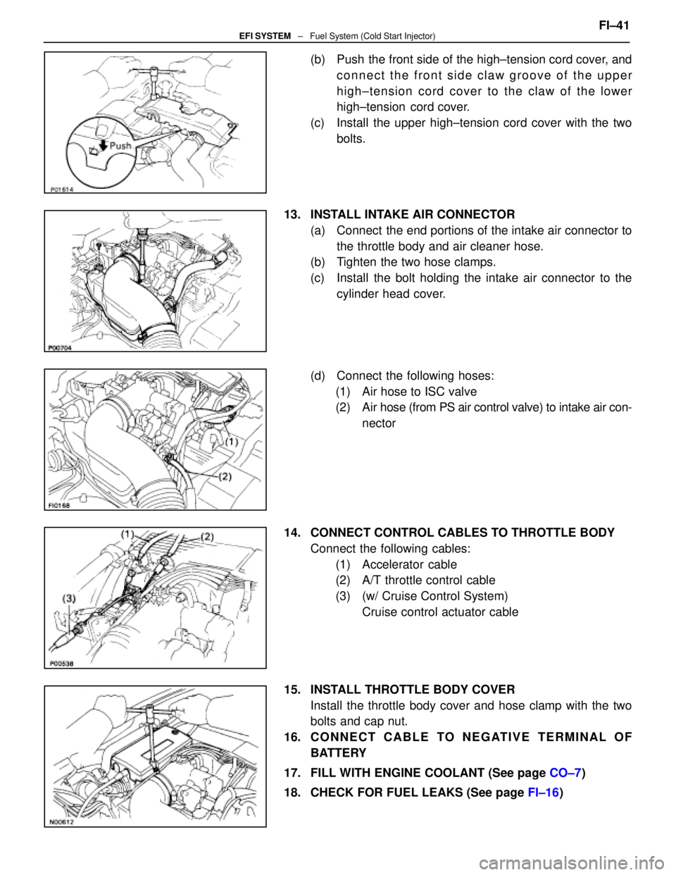
(b) Push the front side of the high±tension cord cover, andconnect the front side claw groove of the upper
high±tension cord cover to the claw of the lower
high±tension cord cover.
(c) Install the upper high±tension cord cover with the two bolts.
13. INSTALL INTAKE AIR CONNECTOR (a) Connect the end portions of the intake air connector tothe throttle body and air cleaner hose.
(b) Tighten the two hose clamps.
(c) Install the bolt holding the intake air connector to the
cylinder head cover.
(d) Connect the following hoses: (1) Air hose to ISC valve
(2) Air hose (from PS air control valve) to intake air con- nector
14. CONNECT CONTROL CABLES TO THROTTLE BODY Connect the following cables:(1) Accelerator cable
(2) A/T throttle control cable
(3) (w/ Cruise Control System) Cruise control actuator cable
15. INSTALL THROTTLE BODY COVER Install the throttle body cover and hose clamp with the two
bolts and cap nut.
16. C O N N E C T C A B L E TO N E G AT I V E T E R M I N A L O F BATTERY
17. FILL WITH ENGINE COOLANT (See page CO±7)
18. CHECK FOR FUEL LEAKS (See page FI±16) FI±41
EFI SYSTEM
± Fuel System (Cold Start Injector)
WhereEverybodyKnowsYourName
Page 2063 of 4087
Injectors
ON±VEHICLE INSPECTION
1. INSPECT INJECTOR OPERATIONCheck operation sound from each injector.
(a) With the engine running or cranking, use a stethescopeto check that there is normal operating noise in
proportion to engine rpm.
(b) If you have no stethescope, you can check the injector transmission operation with your finger.
If no sound or an unusual sound is heard, check the wiring
connector, injector or injection signal from the ECU.
2. INSPECT INJECTOR RESISTANCE (a) Disconnect the injector connector.
(b) Using an ohmmeter, measure the resistance betweenthe terminals.
Resistance: 13.4±14.2 � at 20 5C (68 5F)
If the resistance is not as specified, replace the injector.
(c) Reconnect the injector connector.
FI±26
±
EFI SYSTEM Fuel System (Injectors)
WhereEverybodyKnowsYourName
Page 2068 of 4087
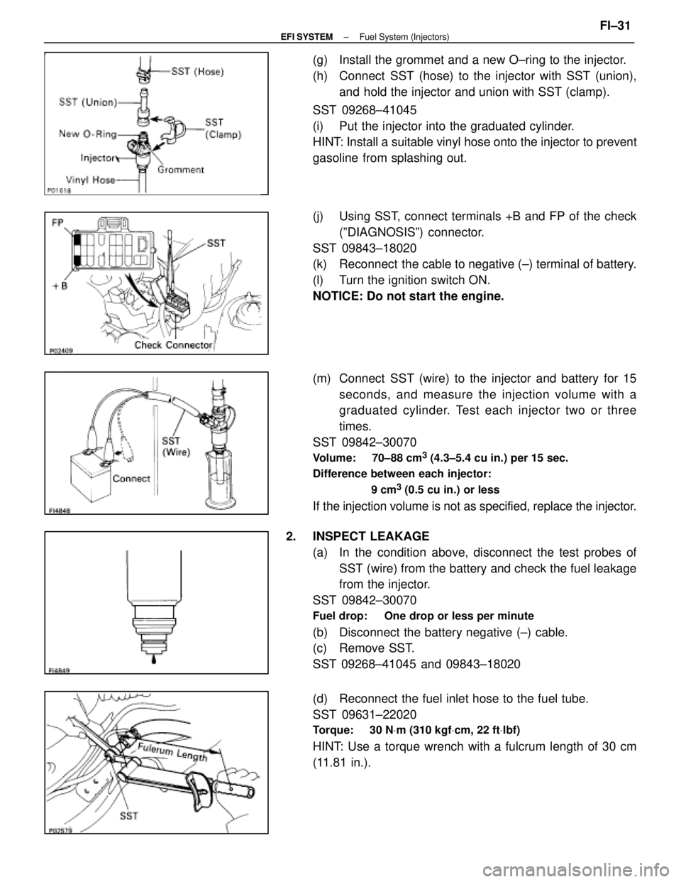
(g) Install the grommet and a new O±ring to the injector.
(h) Connect SST (hose) to the injector with SST (union),and hold the injector and union with SST (clamp).
SST 09268±41045
(i) Put the injector into the graduated cylinder.
HINT: Install a suitable vinyl hose onto the injector to prevent
gasoline from splashing out.
(j) Using SST, connect terminals +B and FP of the check (ºDIAGNOSISº) connector.
SST 09843±18020
(k) Reconnect the cable to negative (±) terminal of battery.
(l) Turn the ignition switch ON.
NOTICE: Do not start the engine.
(m) Connect SST (wire) to the injector and battery for 15 seconds, and measure the injection volume with a
graduated cylinder. Test each injector two or three
times.
SST 09842±30070
Volume: 70±88 cm3 (4.3±5.4 cu in.) per 15 sec.
Difference between each injector:
9 cm
3 (0.5 cu in.) or less
If the injection volume is not as specified, replace the injector.
2. INSPECT LEAKAGE (a) In the condition above, disconnect the test probes ofSST (wire) from the battery and check the fuel leakage
from the injector.
SST 09842±30070
Fuel drop: One drop or less per minute
(b) Disconnect the battery negative (±) cable.
(c) Remove SST.
SST 09268±41045 and 09843±18020
(d) Reconnect the fuel inlet hose to the fuel tube.
SST 09631±22020
Torque: 30 N Vm (310 kgf Vcm, 22 ft Vlbf)
HINT: Use a torque wrench with a fulcrum length of 30 cm
(11.81 in.).
±
EFI SYSTEM Fuel System (Injectors)FI±31
WhereEverybodyKnowsYourName
Page 2086 of 4087
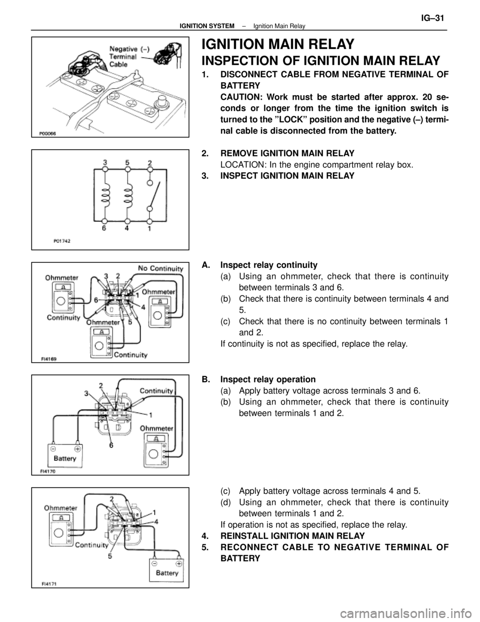
IGNITION MAIN RELAY
INSPECTION OF IGNITION MAIN RELAY
1. DISCONNECT CABLE FROM NEGATIVE TERMINAL OFBATTERY
CAUTION: Work must be started after approx. 20 se-
conds or longer from the time the ignition switch is
turned to the ºLOCKº position and the negative (±) termi-
nal cable is disconnected from the battery.
2. REMOVE IGNITION MAIN RELAY LOCATION: In the engine compartment relay box.
3. INSPECT IGNITION MAIN RELAY
A. Inspect relay continuity
(a) Using an ohmmeter, check that there is continuitybetween terminals 3 and 6.
(b) Check that there is continuity between terminals 4 and 5.
(c) Check that there is no continuity between terminals 1 and 2.
If continuity is not as specified, replace the relay.
B. Inspect relay operation (a) Apply battery voltage across terminals 3 and 6.
(b) Using an ohmmeter, check that there is continuitybetween terminals 1 and 2.
(c) Apply battery voltage across terminals 4 and 5.
(d) Using an ohmmeter, check that there is continuity between terminals 1 and 2.
If operation is not as specified, replace the relay.
4. REINSTALL IGNITION MAIN RELAY
5. RECONNECT CABLE TO NEGATIVE TERMINAL OF BATTERY
±
IGNITION SYSTEM Ignition Main RelayIG±31
WhereEverybodyKnowsYourName