Page 2126 of 4087
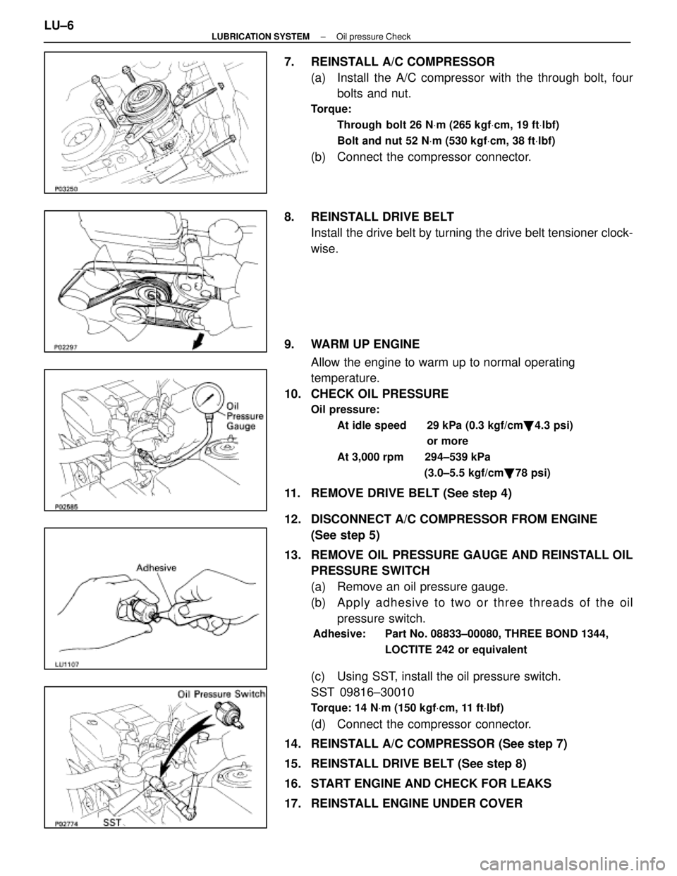
7. REINSTALL A/C COMPRESSOR(a) Install the A/C compressor with the through bolt, fourbolts and nut.
Torque:
Through bolt 26 N Vm (265 kgf Vcm, 19 ft Vlbf)
Bolt and nut 52 N Vm (530 kgf Vcm, 38 ft Vlbf)
(b) Connect the compressor connector.
8. REINSTALL DRIVE BELT Install the drive belt by turning the drive belt tensioner clock-
wise.
9. WARM UP ENGINE Allow the engine to warm up to normal operating
temperature.
10. CHECK OIL PRESSURE
Oil pressure:
At idle speed 29 kPa (0.3 kgf/cm �, 4.3 psi)
or more
At 3,000 rpm 294±539 kPa (3.0±5.5 kgf/cm�, 78 psi)
11. REMOVE DRIVE BELT (See step 4)
12. DISCONNECT A/C COMPRESSOR FROM ENGINE
(See step 5)
13. REMOVE OIL PRESSURE GAUGE AND REINSTALL OIL PRESSURE SWITCH
(a) Remove an oil pressure gauge.
(b) A p p ly a dhesive to two or three threads of the oil
pressure switch.
Adhesive: Part No. 08833±00080, THREE BOND 1344,
LOCTITE 242 or equivalent
(c) Using SST, install the oil pressure switch.
SST 09816±30010
Torque: 14 NVm (150 kgf Vcm, 11 ft Vlbf)
(d) Connect the compressor connector.
14. REINSTALL A/C COMPRESSOR (See step 7)
15. REINSTALL DRIVE BELT (See step 8)
16. START ENGINE AND CHECK FOR LEAKS
17. REINSTALL ENGINE UNDER COVER
LU±6
±
LUBRICATION SYSTEM Oil pressure Check
WhereEverybodyKnowsYourName
Page 2127 of 4087
REPLACEMENT OF ENGINE OIL
AND OIL FILTER
CAUTION:
wProlonged and repeated contact with mineral oil will
result in the removal of natural fats from the skin, leading
to dryness, irritation and dermatitis. In addition, used
engine oil contains potentially harmful contaminants
which may cause skin cancer.
w Exerise caution in order to minimize the length and
frequency of contact of your skin to used oil. Wear
protective clothing and gloves. The skin s hould be
thoroughly w ashed with soap and water, or use waterless
hand cleaner, to remove any used engine oil. Do not use
gasoline, thinners, or solvents.
w In order to preserve the environment, used oil and used
oil filter must be disposed of only at designated disposal
sites.
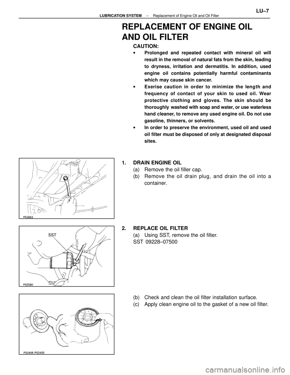
1. DRAIN ENGINE OIL
(a) Remove the oil filler cap.
(b) Remove the oil drain plug, and drain the oil into acontainer.
2. REPLACE OIL FILTER (a) Using SST, remove the oil filter.
SST 09228±07500
(b) Check and clean the oil filter installation surface.
(c) Apply clean engine oil to the gasket of a new oil filter.
±
LUBRICATION SYSTEM Replacement of Engine Oil and Oil FilterLU±7
WhereEverybodyKnowsYourName
Page 2128 of 4087
(d) Lightly screw the oil filter into place, and tighten it untilthe gasket contacts the seat.
(e) Using SST, tighten it an additional 3/4 turn.
SST 09228±07500
3. FILL WITH ENGINE OIL (a) Clean and install the oil drain plug with a new gasket.
Torque: 45 N Vm (450 kgf Vcm, 33 ft Vlbf)
(b) Fill with fresh engine oil.
Oil grade: See page LU±5
Capacity:
Drain and refill w/ Oil filter change
4.8 liters (5.1 US qts, 4.2 lmp. qts)
w/o Oil filter change
4.5 liters (4.8 US qts, 4.0 lmp. qts)
Dry fill 5.2 liters (5.5 US qts, 4.6 lmp. qts)
(c) Reinstall the oil filler cap.
4. START ENGINE AND CHECK FOR LEAKS
5. RECHECK ENGINE OIL LEVEL (See page LU±5)
LU±8
±
LUBRICATION SYSTEM Replacement of Engine Oil and Oil Filter
WhereEverybodyKnowsYourName
Page 2134 of 4087
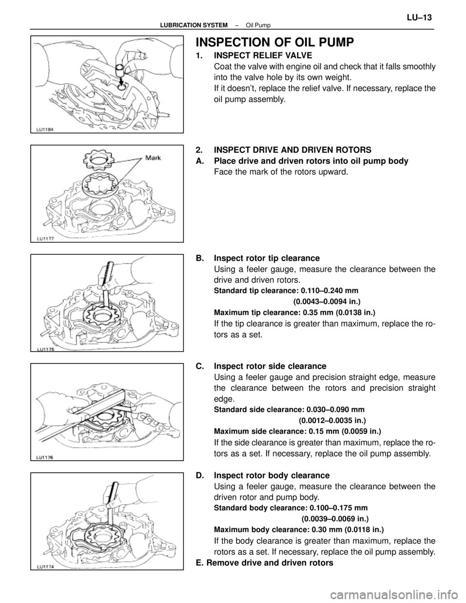
INSPECTION OF OIL PUMP
1. INSPECT RELIEF VALVECoat the valve with engine oil and check that it falls smoothly
into the valve hole by its own weight.
If it doesn't, replace the relief valve. If necessary, replace the
oil pump assembly.
2. INSPECT DRIVE AND DRIVEN ROTORS
A. Place drive and driven rotors into oil pump body Face the mark of the rotors upward.
B. Inspect rotor tip clearance Using a feeler gauge, measure the clearance between the
drive and driven rotors.
Standard tip clearance: 0.110±0.240 mm
(0.0043±0.0094 in.)
Maximum tip clearance: 0.35 mm (0.0138 in.)
If the tip clearance is greater than maximum, replace the ro-
tors as a set.
C. Inspect rotor side clearance Using a feeler gauge and precision straight edge, measure
the clearance between the rotors and precision straight
edge.
Standard side clearance: 0.030±0.090 mm
(0.0012±0.0035 in.)
Maximum side clearance: 0.15 mm (0.0059 in.)
If the side clearance is greater than maximum, replace the ro-
tors as a set. If necessary, replace the oil pump assembly.
D. Inspect rotor body clearance Using a feeler gauge, measure the clearance between the
driven rotor and pump body.
Standard body clearance: 0.100±0.175 mm
(0.0039±0.0069 in.)
Maximum body clearance: 0.30 mm (0.0118 in.)
If the body clearance is greater than maximum, replace the
rotors as a set. If necessary, replace the oil pump assembly.
E. Remove drive and driven rotors
±
LUBRICATION SYSTEM Oil PumpLU±13
WhereEverybodyKnowsYourName
Page 2145 of 4087
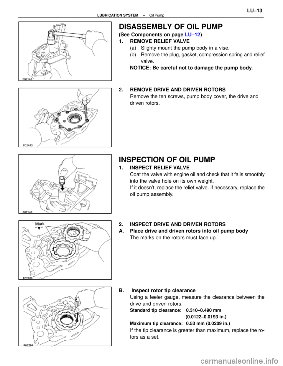
DISASSEMBLY OF OIL PUMP
(See Components on page LU±12)
1. REMOVE RELIEF VALVE (a) Slighty mount the pump body in a vise.
(b) Remove the plug, gasket, compression spring and reliefvalve.
NOTICE: Be careful not to damage the pump body.
2. REMOVE DRIVE AND DRIVEN ROTORS Remove the ten screws, pump body cover, the drive and
driven rotors.
INSPECTION OF OIL PUMP
1. INSPECT RELIEF VALVECoat the valve with engine oil and check that it falls smoothly
into the valve hole on its own weight.
If it doesn't, replace the relief valve. If necessary, replace the
oil pump assembly.
2. INSPECT DRIVE AND DRIVEN ROTORS
A. Place drive and driven rotors into oil pump body The marks on the rotors must face up.
B. Inspect rotor tip clearance Using a feeler gauge, measure the clearance between the
drive and driven rotors.
Standard tip clearance: 0.310±0.490 mm
(0.0122±0.0193 in.)
Maximum tip clearance: 0.53 mm (0.0209 in.)
If the tip clearance is greater than maximum, replace the ro-
tors as a set.
±
LUBRICATION SYSTEM Oil PumpLU±13
WhereEverybodyKnowsYourName
Page 2157 of 4087
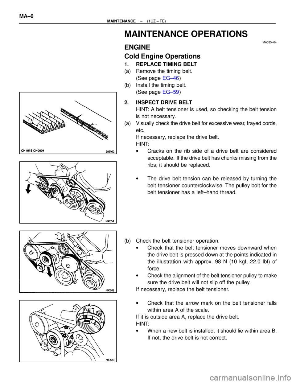
MAINTENANCE OPERATIONS
MA035±04
ENGINE
Cold Engine Operations
1. REPLACE TIMING BELT
(a) Remove the timing belt.(See page EG±46)
(b) Install the timing belt. (See page EG±59)
2. INSPECT DRIVE BELT HINT: A belt tensioner is used, so checking the belt tension
is not necessary.
(a) Visually check the drive belt for excessive wear, frayed cords,
etc.
If necessary, replace the drive belt.
HINT:
w Cracks on the rib side of a drive belt are considered
acceptable. If the drive belt has chunks missing from the
ribs, it should be replaced.
w The drive belt tension can be released by turning the
belt tensioner counterclockwise. The pulley bolt for the
belt tensioner has a left±hand thread.
(b) Check the belt tensioner operation. wCheck that the belt tensioner moves downward when
the drive belt is pressed down at the points indicated in
the illustration with approx. 98 N (10 kgf, 22.0 lbf) of
force.
w Check the ali gnment of the belt tensioner pulley to make
sure the drive belt will not slip off the pulley.
If necessary, replace the belt tensioner.
w Check that the arrow mark on the belt tensioner falls
within area A of the scale.
If it is outside area A, replace the drive belt.
HINT:
w When a new belt is installed, it should lie within area B.
If not, the drive belt is not correct.
MA±6
±
MAINTENANCE (1UZ ± FE)
WhereEverybodyKnowsYourName
Page 2160 of 4087
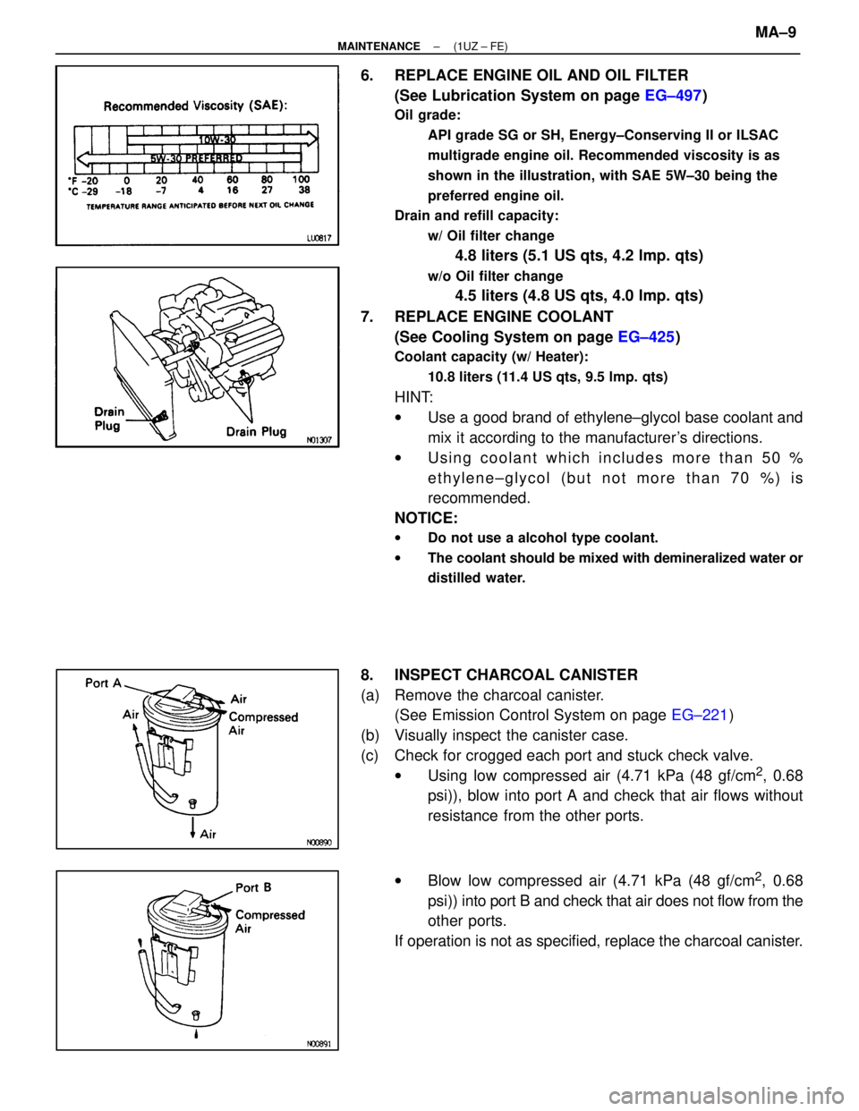
6. REPLACE ENGINE OIL AND OIL FILTER(See Lubrication System on page EG±497)
Oil grade:
API grade SG or SH, Energy±Conserving II or ILSAC
multigrade engine oil. Recommended viscosity is as
shown in the illustration, with SAE 5W±30 being the
preferred engine oil.
Drain and refill capacity:
w/ Oil filter change
4.8 liters (5.1 US qts, 4.2 lmp. qts)
w/o Oil filter change
4.5 liters (4.8 US qts, 4.0 lmp. qts)
7. REPLACE ENGINE COOLANT (See Cooling System on page EG±425)
Coolant capacity (w/ Heater):
10.8 liters (11.4 US qts, 9.5 lmp. qts)
HINT:
wUse a good brand of ethylene±glycol base coolant and
mix it according to the manufacturer's directions.
w Using coolant which includes more than 50 %
ethylene±glycol (but not more than 70 %) is
recommended.
NOTICE:
w Do not use a alcohol type coolant.
w The coolant should be mixed with demineralized water or
distilled water.
8. INSPECT CHARCOAL CANISTER
(a) Remove the charcoal canister.
(See Emission Control System on page EG±221)
(b) Visually inspect the canister case.
(c) Check for crogged each port and stuck check valve. wUsing low compressed air (4.71 kPa (48 gf/cm
2, 0.68
psi)), blow into port A and check that air flows without
resistance from the other ports.
w Blow low compressed air (4.71 kPa (48 gf/cm
2, 0.68
psi)) into port B and check that air does not flow from the
other ports.
If operation is not as specified, replace the charcoal canister.
±
MAINTENANCE (1UZ ± FE)MA±9
WhereEverybodyKnowsYourName
Page 2161 of 4087

(d) Clean the filter in the canister.Clean the filter by blowing 294 kPa (3 kgf/cm
2, 43 psi) of com-
pressed air into port A while holding port B closed.
NOTICE:
w Do not attempt to wash the canister.
w No activated carbon should come out.
(e) Reinstall the charcoal canister.
(See Emission Control System on page EG±222)
9. REPLACE GASKET IN FUEL TANK CAP
(a) Remove the old gasket from the tank cap. Do not damage the
cap.
(b) Install a new gasket by hand.
(c) Check the cap for damage or cracks.
(d) Install the cap and check the torque limiter.
10. INSPECT FUEL LINES AND CONNECTIONS Visually check the fuel lines for cracks, leakage, loose con-
nections, deformation or tank band looseness.
11. INSPECT EXHAUST PIPES AND MOUNTINGS Visually check the pipes, hangers and connections for se-
vere corrosion, leaks or damage.
12. ADJUST VALVE CLEARANCE (See Engine Mechanical on page EG±14)
Valve clearance (Cold):
Intake
.15 ± 0.25 mm (0.006 ± 0.010 in.)
Exhaust
.25 ± 0.35 mm (0.010 ± 0.014 in.)
MA±10
±
MAINTENANCE (1UZ ± FE)
WhereEverybodyKnowsYourName