Page 2216 of 4087
(b) Check that the timing marks of the camshaft timingpulleys and timing belt rear plates aligned.
If not, turn the crankshaft one revolution (360 5) and align the
mark as above.
20. INSPECT VALVE CLEARANCE (a) Check only those valves indicated.w Using a feeler gauge, measure the clearance
between the valve lifter and camshaft.
w Record the out±of±specification valve clearance
measurements. They will be used later to
determine the required replacement adjusting
shim.
Valve clearance (Cold):
Intake 0.15±0.25 mm (0.006±0.010 in.)
Exhaust 0.25±0.35 mm (0.010±0.014 in.)
(b) Turn the crankshaft one revolution (360 °), and align the
mark as above. (See procedure step in 19 (a))
(c) Check only the valves indicated as shown. Measure the
valve clearance.
(See procedure in step (a))
EM±16
±
ENGINE MECHANICAL Engine Tune±Up
WhereEverybodyKnowsYourName
Page 2219 of 4087
(b) Determine the replacement adjusting shim sizefollowing Formula or Charts:
w Using a micrometer, measure the thickness of the
removed shim.
w Calculate the thickness of a new shim so the valve
clearance comes within specified value.
T
Thickness of used shim
A
Measured valve clearance
N
Thickness of new shim
Intake N = T + (A±0.20 mm (0.008 in.))
Exhaust N = T + (A±0.30 mm (0.012 in.))
w Select a new shim with a thickness as close as
possible to the calculated values.
HINT: Shims are available in thirty±three sizes in increments
of 0.025 mm (0.0010 in.), from 2.50 mm (0.0984 in.) to 3.30
mm (0.1299 in.).
(c) Install a new adjusting shim. w Place a new adjusting shim on the valve lifter.
w Press down the valve lifter with SST (A), and
remove SST (B).
SST 09248±55011
(d) Recheck the valve clearance.
±
ENGINE MECHANICAL Engine Tune±UpEM±19
WhereEverybodyKnowsYourName
Page 2228 of 4087

IDLE AND/OR 2,500 RPM HC/CO
CONCENTRATION CHECK METHOD
HINT: This check is used only to determine whether or not the
idle HC/CO complies with regulations.
1. INTIAL CONDITIONS (a) Engine at normal operating temperature.
(b) Air cleaner installed.
(c) All pipes and hoses of air induction system connected.
(d) All accessories switched OFF.
(e) All vacuum lines properly connected.
HINT: All vacuum hoses for EGR systems, etc. should be
properly connected.
(f) EFI system wiring connectors fully plugged.
(g) Transmission in neutral range.
(h) Tachometer and HC/CO meter calibrated at hand.
2. START ENGINE
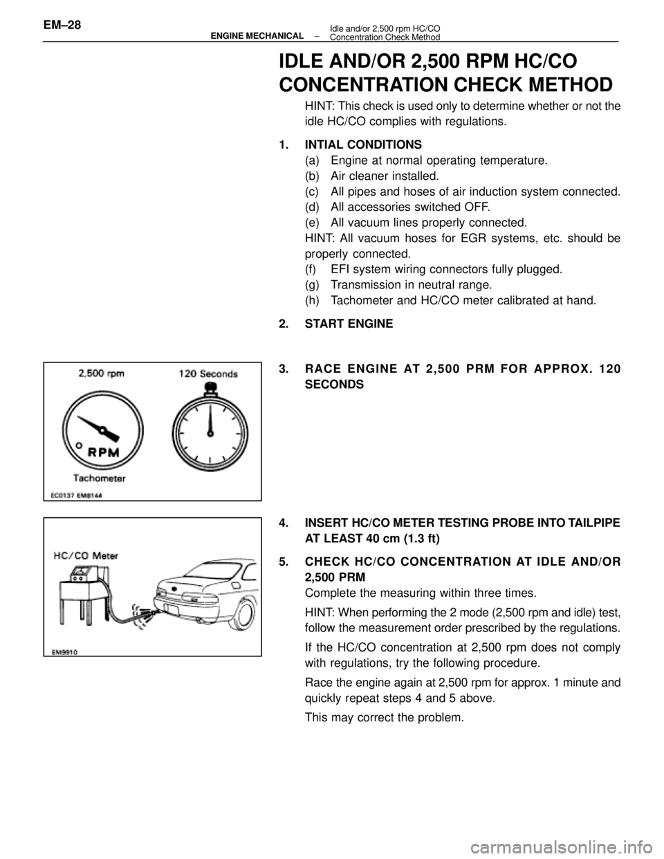
3. RACE ENGINE AT 2,500 PRM FOR APPROX. 120 SECONDS
4. INSERT HC/CO METER TESTING PROBE INTO TAILPIPE AT LEAST 40 cm (1.3 ft)
5. CHECK HC/CO CONCENTRATION AT IDLE AND/OR 2,500 PRM
Complete the measuring within three times.
HINT: When performing the 2 mode (2,500 rpm and idle) test,
follow the measurement order prescribed by the regulations.
If the HC/CO concentration at 2,500 rpm does not comply
with regulations, try the following procedure.
Race the engine again at 2,500 rpm for approx. 1 minute and
quickly repeat steps 4 and 5 above.
This may correct the problem.
EM±28
±
ENGINE MECHANICAL Idle and/or 2,500 rpm HC/CO
Concentration Check Method
WhereEverybodyKnowsYourName
Page 2229 of 4087

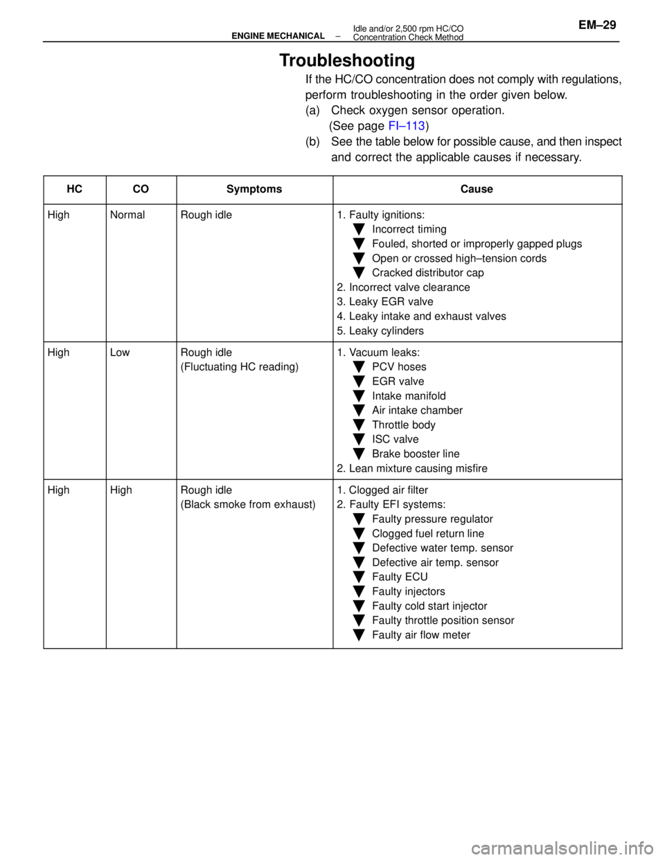
Troubleshooting
If the HC/CO concentration does not comply with regulations,
perform troubleshooting in the order given below.
(a) Check oxygen sensor operation.(See page FI±113)
(b) See the table below for possible cause, and then inspect
and correct the applicable causes if necessary.
����� �
����
�����HC����� �
����
�����CO���������� �
���������
����������Symptoms������������������\
� �
������������������
������������������\
�Cause
����� �����High����� �����Normal���������� ����������Rough idle������������������\
� ������������������\
�1. Faulty ignitions:
����� ���������� ��������������� ����������������������������\
� ������������������\
��Incorrect timing
����� ���������� ��������������� ����������������������������\
� ������������������\
��Fouled, shorted or improperly gapped plugs
����� ���������� ��������������� ����������������������������\
� ������������������\
��Open or crossed high±tension cords
Ckddiib��������������������������������������\
��Cracked distributor cap
Ill����� ���������� ��������������� ����������������������������\
� ������������������\
�2. Incorrect valve clearance
3 L k EGR l����� ���������� ��������������� ����������������������������\
� ������������������\
�3. Leaky EGR valve
4L k i k d h l����� ���������� ��������������� ����������������������������\
� ������������������\
�4. Leaky intake and exhaust valves
L k li d����� ���������� ��������������� ����������������������������\
� ������������������\
�5. Leaky cylinders
����� �����High����� �����Low���������� ����������Rough idle������������������\
� ������������������\
�1. Vacuum leaks:
����� ���������� ��������������� ����������(Fluctuating HC reading)������������������\
� ������������������\
��PCV hoses
����� ���������� ��������������� ����������������������������\
� ������������������\
��EGR valve
����� ���������� ��������������� ����������������������������\
� ������������������\
��Intake manifold
Ai i k h b����� ���������� ��������������� ����������������������������\
� ������������������\
��Air intake chamber
Th l b d����� ���������� ��������������� ����������������������������\
� ������������������\
��Throttle body
ISC l��������������������������������������\
��ISC valve
Bkb li����� ���������� ��������������� ����������������������������\
� ������������������\
��Brake booster line
2L i i ifi����� ���������� ��������������� ����������������������������\
� ������������������\
�2. Lean mixture causing misfire
����� �����High����� �����High���������� ����������Rough idle������������������\
� ������������������\
�1. Clogged air filter����� �����g����� �����g���������� ����������g
(Black smoke from exhaust)������������������\
� ������������������\
�gg
2. Faulty EFI systems:����� ���������� ��������������� ����������()������������������\
� ������������������\
�yy
�Faulty pressure regulator
����� ���������� ��������������� ����������������������������\
� ������������������\
�
yg
�Clogged fuel return line
����� ���������� ��������������� ����������������������������\
� ������������������\
�
gg
�Defective water temp. sensor
����� ���������� ��������������� ����������������������������\
� ������������������\
��Defective air temp. sensor
����� ���������� ��������������� ����������������������������\
� ������������������\
��Faulty ECU
����� ���������� ��������������� ����������������������������\
� ������������������\
�
y
�Faulty injectors
��������������������������������������\
�
yj
�Faulty cold start injector����� ���������� ��������������� ����������������������������\
� ������������������\
�yj
�Faulty throttle position sensor����� ���������� ��������������� ����������������������������\
� ������������������\
��Faulty air flow meter
±
ENGINE MECHANICAL Idle and/or 2,500 rpm HC/CO
Concentration Check MethodEM±29
WhereEverybodyKnowsYourName
Page 2230 of 4087
COMPRESSION CHECK
HINT: If there is lack of power, excessive oil consumption or
poor fuel economy, measure the compression pressure.
1. WARM UP AND STOP ENGINE Allow the engine to warm up to normal operating tempera-
ture.
2. REMOVE NO.3 TIMING BELT COVERS (See steps 1, 5 to 10 and 14 on pages EM±11 to 13)
3. DISCONNECT COLD START INJECTOR CONNECTOR
4. DISCONNECT RH CAM POSITION SENSOR CONNECTOR
(a) Disconnect the connector from the ignition coil bracket.
(b) Disconnect the sensor connector.
5. DISCONNECT LH CAM POSITION SENSOR CONNECTOR
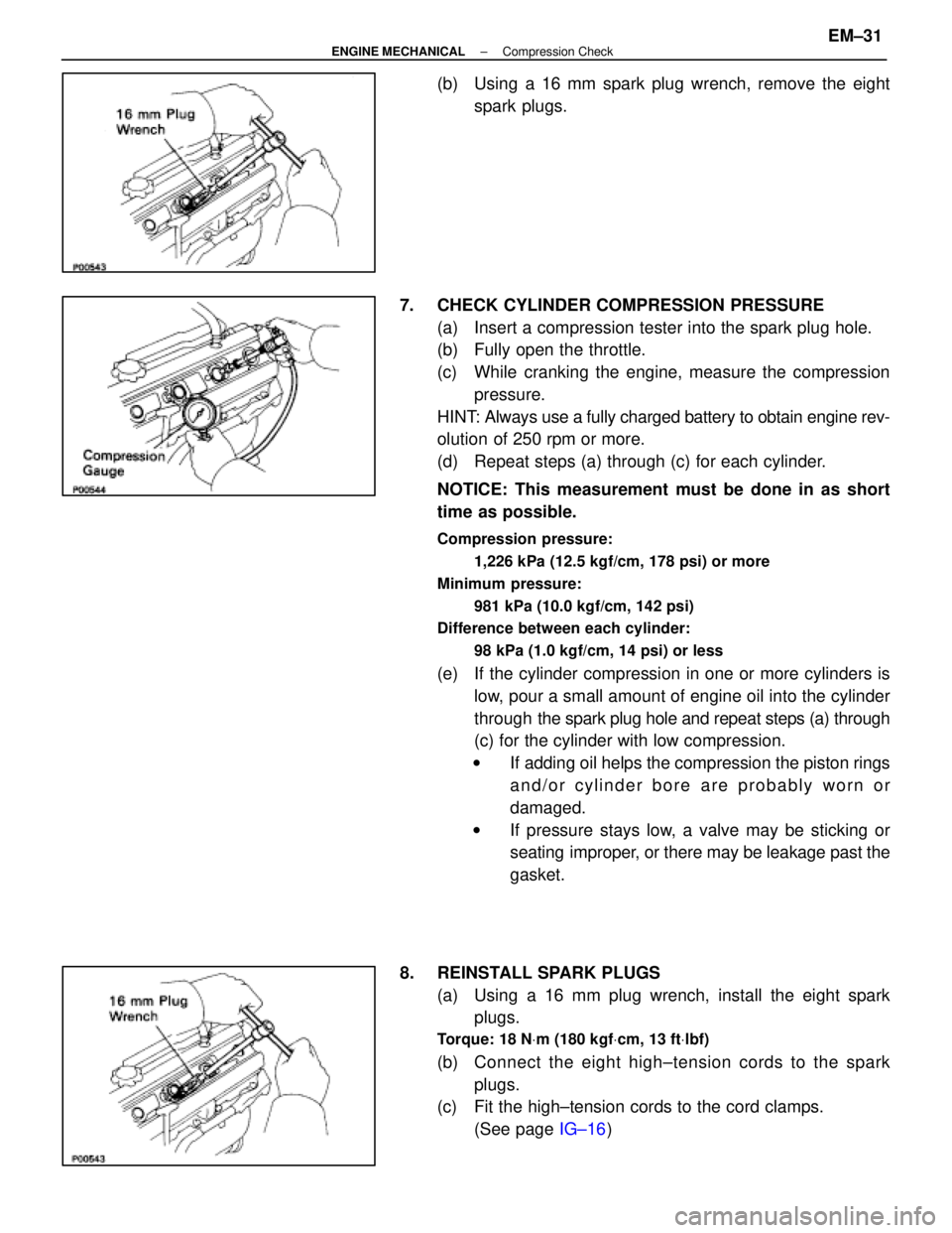
6. REMOVE SPARK PLUGS (a) Disconnect the eight high±tension cords from the sparkplugs.
Disconnect the high±tension cords at rubber boot. Do
not pull on the cords.
NOTICE: Pulling on or bending the cords may damage
the conductor inside.
EM±30
±
ENGINE MECHANICAL Compression Check
WhereEverybodyKnowsYourName
Page 2231 of 4087

(b) Using a 16 mm spark plug wrench, remove the eightspark plugs.
7. CHECK CYLINDER COMPRESSION PRESSURE (a) Insert a compression tester into the spark plug hole.
(b) Fully open the throttle.
(c) While cranking the engine, measure the compressionpressure.
HINT: Always use a fully charged battery to obtain engine rev-
olution of 250 rpm or more.
(d) Repeat steps (a) through (c) for each cylinder.
NOTICE: This measurement must be done in as short
time as possible.
Compression pressure:
1,226 kPa (12.5 kgf/cm, 178 psi) or more
Minimum pressure: 981 kPa (10.0 kgf/cm, 142 psi)
Difference between each cylinder:
98 kPa (1.0 kgf/cm, 14 psi) or less
(e) If the cylinder compression in one or more cylinders islow, pour a small amount of engine oil into the cylinder
through the spark plug hole and repeat steps (a) through
(c) for the cylinder with low compression.
w If adding oil helps the compression the piston rings
and/or cylinder bore are probably worn or
damaged.
w If pressure stays low, a valve may be sticking or
seating improper, or there may be leakage past the
gasket.
8. REINSTALL SPARK PLUGS (a) Using a 16 mm plug wrench, install the eight sparkplugs.
Torque: 18 N Vm (180 kgf Vcm, 13 ft Vlbf)
(b) C onnect the eight high±tension cords to the spark
plugs.
(c) Fit the high±tension cords to the cord clamps.
(See page IG±16)
±
ENGINE MECHANICAL Compression CheckEM±31
WhereEverybodyKnowsYourName
Page 2232 of 4087
9. RECONNECT RH CAM POSITION SENSOR CONNECTOR
(a) Connect the sensor connector.
(b) Connect the connector to the ignition coil bracket.
10. RECONNECT LH CAM POSITION SENSOR CONNECTOR
11. RECONNECT COLD START INJECTOR CONNECTOR
12. REINSTALL NO.3 TIMING BELT COVERS (See steps 28 to 30, 34 to 37, 40 and 41 on pages EM±25
to 27)
EM±32
±
ENGINE MECHANICAL Compression Check
WhereEverybodyKnowsYourName
Page 2240 of 4087
22. REMOVE ALTERNATOR(a) Disconnect the alternator connector.
(b) Remove the cap and nut, and disconnect the alternatorwire.
(c) Remove the bolt, and disconnect the A/T oil cooler pipe bracket.
(d) Remove the nut and alternator.
23. REMOVE DRIVE BELT TENSIONER Remove the bolt, two nuts and tensioner.
24. REMOVE SPARK PLUGS Using a 16 mm plug wrench, remove the eight spark plugs.
25. IF RE±USING TIMING BELT, CHECK INSTALLATION MARKS ON TIMING BELT
Check that there are four installation marks on the timing belt
by turning the crankshaft pulley as shown in the illustration.
If the installation marks have disappeared, place a new
installation mark on the timing belt before removing each
part.
26. SET NO.1 CYLINDER TO TDC/COMPRESSION (a) Turn the crankshaft pulley and align its groove with thetiming mark ºOº of the No.1 timing belt cover.
EM±40
±
ENGINE MECHANICAL Timing Belt
WhereEverybodyKnowsYourName