Page 2300 of 4087
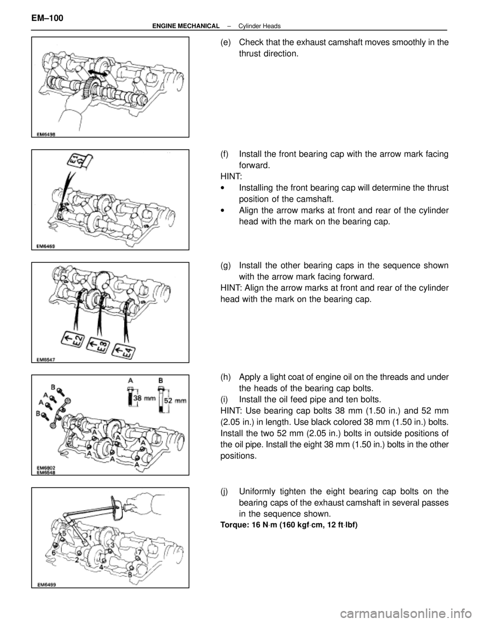
(e) Check that the exhaust camshaft moves smoothly in the
thrust direction.
(f) Install the front bearing cap with the arrow mark facing forward.
HINT:
w Installing the front bearing cap will determine the thrust
position of the camshaft.
w Align the arrow marks at front and rear of the cylinder
head with the mark on the bearing cap.
(g) Install the other bearing caps in the sequence shown with the arrow mark facing forward.
HINT: Align the arrow marks at front and rear of the cylinder
head with the mark on the bearing cap.
(h) Apply a light coat of engine oil on the threads and under
the heads of the bearing cap bolts.
(i) Install the oil feed pipe and ten bolts.
HINT: Use bearing cap bolts 38 mm (1.50 in.) and 52 mm
(2.05 in.) in length. Use black colored 38 mm (1.50 in.) bolts.
Install the two 52 mm (2.05 in.) bolts in outside positions of
the oil pipe. Install the eight 38 mm (1.50 in.) bolts in the other
positions.
(j) Uniformly tighten the eight bearing cap bolts on the
bearing caps of the exhaust camshaft in several passes
in the sequence shown.
Torque: 16 N Vm (160 kgf Vcm, 12 ft Vlbf)
EM±100±
ENGINE MECHANICAL Cylinder Heads
WhereEverybodyKnowsYourName
Page 2301 of 4087
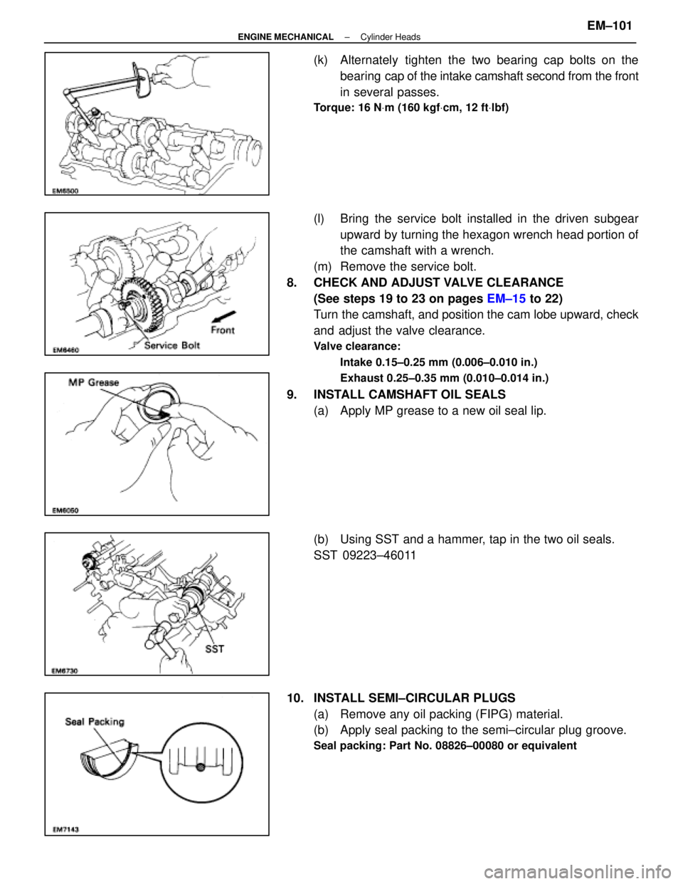
(k) Alternately tighten the two bearing cap bolts on thebearing cap of the intake camshaft second from the front
in several passes.
Torque: 16 N Vm (160 kgf Vcm, 12 ft Vlbf)
(l) Bring the service bolt installed in the driven subgear
upward by turning the hexagon wrench head portion of
the camshaft with a wrench.
(m) Remove the service bolt.
8. CHECK AND ADJUST VALVE CLEARANCE (See steps 19 to 23 on pages EM±15 to 22)
Turn the camshaft, and position the cam lobe upward, check
and adjust the valve clearance.
Valve clearance:
Intake 0.15±0.25 mm (0.006±0.010 in.)
Exhaust 0.25±0.35 mm (0.010±0.014 in.)
9. INSTALL CAMSHAFT OIL SEALS(a) Apply MP grease to a new oil seal lip.
(b) Using SST and a hammer, tap in the two oil seals.
SST 09223±46011
10. INSTALL SEMI±CIRCULAR PLUGS (a) Remove any oil packing (FIPG) material.
(b) Apply seal packing to the semi±circular plug groove.
Seal packing: Part No. 08826±00080 or equivalent
±
ENGINE MECHANICAL Cylinder HeadsEM±101
WhereEverybodyKnowsYourName
Page 2305 of 4087
22. INSTALL DELIVERY PIPES AND INJECTORS(a) Install the grommet and a new O±ring to each injector.
(b) W h i l e t u r n i n g t h e I n j e c t o r c l o c k w i s e a n dcounterclockwise, push it to delivery pipe. Install the
eight injectors.
(c) Position the injector connector outward.
(d) Place the eight insulators and four spacers in positions on the intake manifold.
(e) P l a c e t h e e i g h t i n j e c t o r s a n d t w o d e l i v e r y p i p e s assembly in position on the intake manifold.
(f) Temporarily install the c onnector bracket and four
mounting nuts.
(g) Check that the injectors rotates smoothly.
(h) Position the injector connectors outward.
±
ENGINE MECHANICAL Cylinder HeadsEM±105
WhereEverybodyKnowsYourName
Page 2308 of 4087
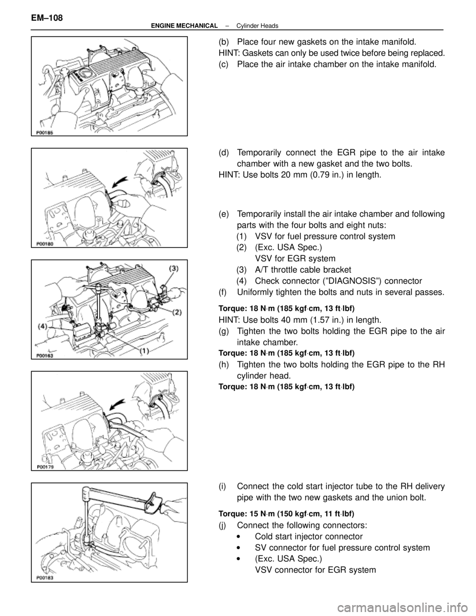
(b) Place four new gaskets on the intake manifold.
HINT: Gaskets can only be used twice before being replaced.
(c) Place the air intake chamber on the intake manifold.
(d) Temporarily connect the EGR pipe to the air intakechamber with a new gasket and the two bolts.
HINT: Use bolts 20 mm (0.79 in.) in length.
(e) Temporarily install the air intake chamber and following
parts with the four bolts and eight nuts:
(1) VSV for fuel pressure control system
(2) (Exc. USA Spec.) VSV for EGR system
(3) A/T throttle cable bracket
(4) Check connector (ºDIAGNOSISº) connector
(f) Uniformly tighten the bolts and nuts in several passes.
Torque: 18 N Vm (185 kgf Vcm, 13 ft Vlbf)
HINT: Use bolts 40 mm (1.57 in.) in length.
(g) Tighten the two bolts holding the EGR pipe to the air
intake chamber.
Torque: 18 N Vm (185 kgf Vcm, 13 ft Vlbf)
(h) Tighten the two bolts holding the EGR pipe to the RH
cylinder head.
Torque: 18 N Vm (185 kgf Vcm, 13 ft Vlbf)
(i) Connect the cold start injector tube to the RH delivery
pipe with the two new gaskets and the union bolt.
Torque: 15 N Vm (150 kgf Vcm, 11 ft Vlbf)
(j) Connect the following connectors:
w Cold start injector connector
w SV connector for fuel pressure control system
w (Exc. USA Spec.)
VSV connector for EGR system
EM±108
±
ENGINE MECHANICAL Cylinder Heads
WhereEverybodyKnowsYourName
Page 2315 of 4087
47. INSTALL PS PUMP(a) In sta ll th e PS pu mp with th e th re e bo lts an d nu t.Alternately tighten the bolts and nut.
Torque:
Bolt 39 N Vm (400 kgf Vcm, 29 ft Vlbf)
Nut 43 N Vm (440 kgf Vcm, 32 ft Vlbf)
(b) Connect the vacuum hose to the vacuum pipe.
48. INSTALL HYDRAULIC PUMP AND CAMSHAFT TIMING PULLEYS
(See steps 8, 10 and 11 on pages EM±48 to 49)
49. INSTALL HYDRAULIC PUMP AND CAMSHAFT TIMING PULLEYS
(See steps 12 to 43 on pages EM±49 to 57)
50. PERFORM ROAD TEST Check for abnormal noise, shock, slippage, correct shift
points and smooth operation.
±
ENGINE MECHANICAL Cylinder HeadsEM±115
WhereEverybodyKnowsYourName
Page 2335 of 4087
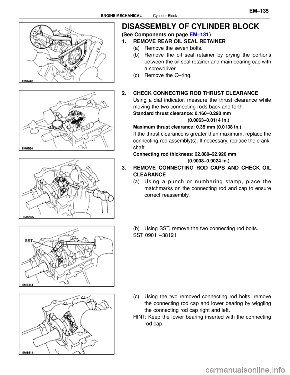
DISASSEMBLY OF CYLINDER BLOCK
(See Components on page EM±131)
1. REMOVE REAR OIL SEAL RETAINER (a) Remove the seven bolts.
(b) Remove the oil seal retainer by prying the portions
between the oil seal retainer and main bearing cap with
a screwdriver.
(c) Remove the O±ring.
2. CHECK CONNECTING ROD THRUST CLEARANCE Using a dial indicator, measure the thrust clearance while
moving the two connecting rods back and forth.
Standard thrust clearance: 0.160±0.290 mm
(0.0063±0.0114 in.)
Maximum thrust clearance: 0.35 mm (0.0138 in.)
If the thrust clearance is greater than maximum, replace the
connecting rod assembly(s). If necessary, replace the crank-
shaft.
Connecting rod thickness: 22.880±22.920 mm (0.9008±0.9024 in.)
3. REMOVE CONNECTING ROD CAPS AND CHECK OILCLEARANCE
(a) Using a punch or numbering stamp, place thematchmarks on the connecting rod and cap to ensure
correct reassembly.
(b) Using SST, remove the two connecting rod bolts.
SST 09011±38121
(c) Using the two removed connecting rod bolts, remove the connecting rod cap and lower bearing by wiggling
the connecting rod cap right and left.
HINT: Keep the lower bearing inserted with the connecting rod cap.
±
ENGINE MECHANICAL Cylinder BlockEM±135
WhereEverybodyKnowsYourName
Page 2338 of 4087
HINT:
wKeep the bearings, connecting rod and cap together.
w Arrange the piston and connecting rod assemblies in
correct order.
5. CHECK CRANKSHAFT THRUST CLEARANCE Using a dial indi cator, measure the thrust clearance while pry-
ing the crankshaft back and forth with a screwdriver.
Standard thrust clearance: 0.020±0.220 mm
(0.0008±0.0087 in.)
Maximum thrust clearance: 0.30 mm (0.0118 in.)
If the thrust clearance is greater than maximum, replace the
thrust washers as a set.
Thrust washer thickness: 2.440±2.490 mm (0.0961±0.0980 in.)
6. REMOVE MAIN BEARING CAP AND CHECK OILCLEARANCE
(a) Remove the ten main bearing cap bolts.
(b) Uniformly loosen and remove the twenty main bearingcap nuts in several passes in the sequence shown.
EM±138
±
ENGINE MECHANICAL Cylinder Block
WhereEverybodyKnowsYourName
Page 2339 of 4087
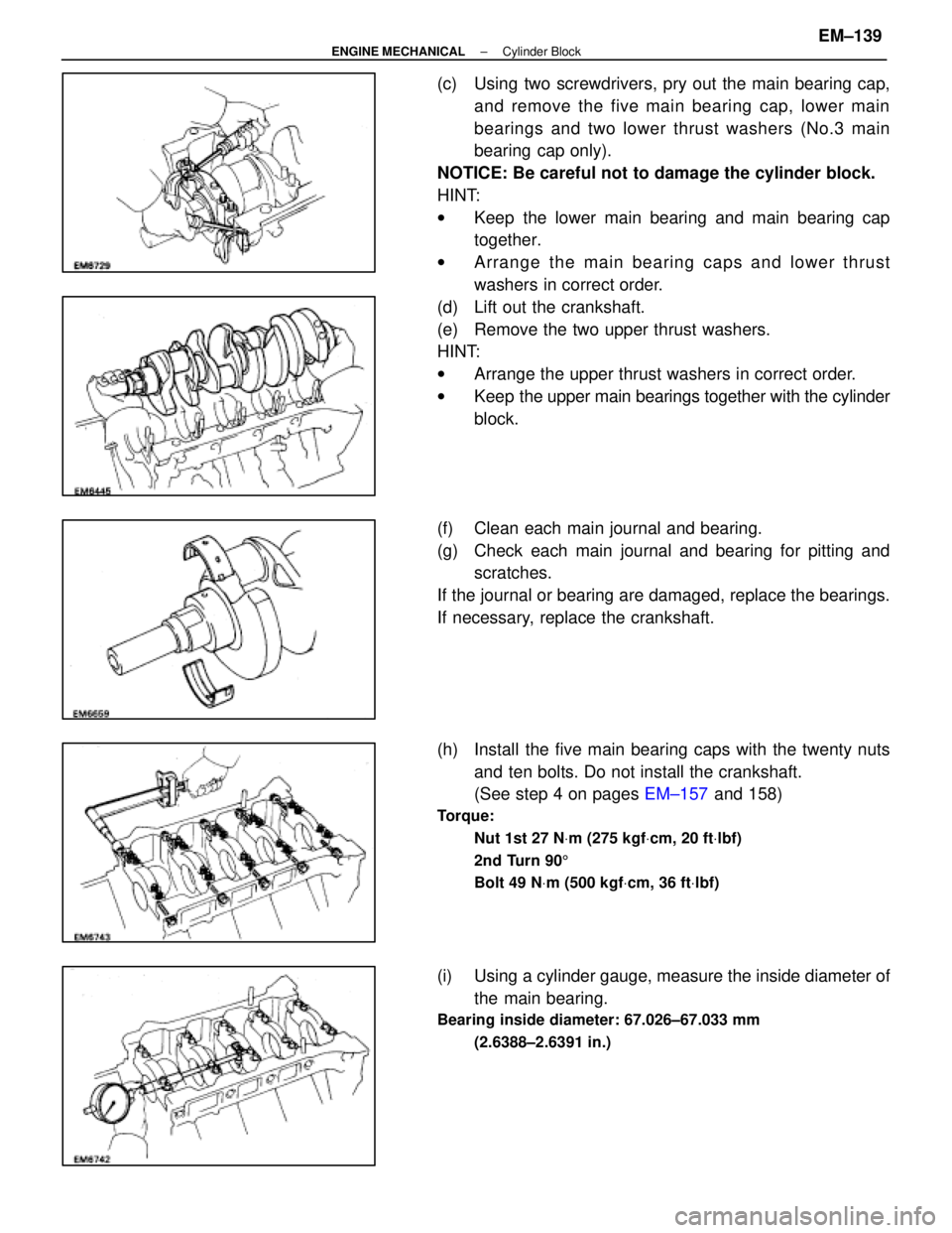
(c) Using two screwdrivers, pry out the main bearing cap,and remove the five main bearing cap, lower main
bearings and two lower thrust washers (No.3 main
bearing cap only).
NOTICE: Be careful not to damage the cylinder block.
HINT:
w Keep the lower main bearing and main bearing cap
together.
w Arrange the main bearing caps and lower thrust
washers in correct order.
(d) Lift out the crankshaft.
(e) Remove the two upper thrust washers.
HINT:
w Arrange the upper thrust washers in correct order.
w Keep the upper main bearings together with the cylinder
block.
(f) Clean each main journal and bearing.
(g) Check each main journal and bearing for pitting and scratches.
If the journal or bearing are damaged, replace the bearings.
If necessary, replace the crankshaft.
(h) Install the five main bearing caps with the twenty nuts and ten bolts. Do not install the crankshaft.
(See step 4 on pages EM±157 and 158)
Torque:
Nut 1st 27 N Vm (275 kgf Vcm, 20 ft Vlbf)
2nd Turn 90 5
Bolt 49 N Vm (500 kgf Vcm, 36 ft Vlbf)
(i) Using a cylinder gauge, measure the inside diameter of
the main bearing.
Bearing inside diameter: 67.026±67.033 mm
(2.6388±2.6391 in.)
±
ENGINE MECHANICAL Cylinder BlockEM±139
WhereEverybodyKnowsYourName