Page 1840 of 4087
5. REMOVE CYLINDER RIDGEIf the wear is less than 0.2 mm (0.008 in.), using a ridge ream-
er, grind the top of the cylinder.
6. INSPECT MAIN BEARING CAP BOLTS Using vernier calipers, measure the minimum diameter of the
compressed thread at the measuring point.
Standard diameter: 9.96±9.97 mm
(0.3921±0.3925 in.)
Minimum diameter: 9.7 mm (0.3819 in.)
If the diameter is less than minimum, replace the bolt.
DISASSEMBLY OF PISTON AND
CONNECTING ROD ASSEMBLIES
1. CHECK FIT BETWEEN PISTON AND PISTON PIN Try to move the piston back and forth on the piston pin.
If any movement is felt, replace the piston and pin as a set.
2. REMOVE PISTON RINGS
(a) Using a piston ring expander, remove the two compression rings.
(b) Remove the two side rails and oil ring expander by hand. HINT: Arrange the piston rings in correct order only.
±
ENGINE MECHANICAL Cylinder BlockEM±85
WhereEverybodyKnowsYourName
Page 1844 of 4087

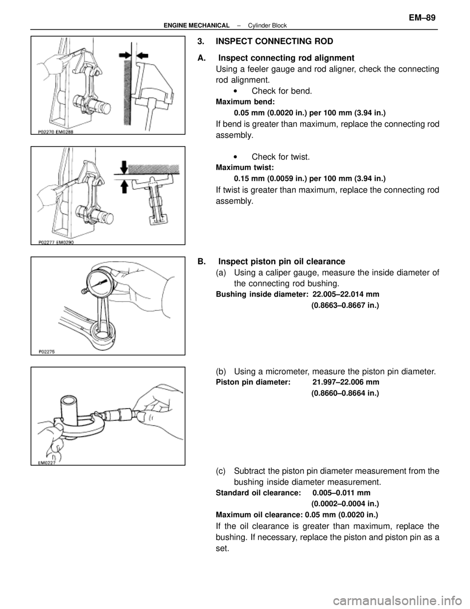
3. INSPECT CONNECTING ROD
A. Inspect connecting rod alignmentUsing a feeler gauge and rod aligner, check the connecting
rod alignment.w Check for bend.
Maximum bend:
0.05 mm (0.0020 in.) per 100 mm (3.94 in.)
If bend is greater than maximum, replace the connecting rod
assembly.
w Check for twist.
Maximum twist:
0.15 mm (0.0059 in.) per 100 mm (3.94 in.)
If twist is greater than maximum, replace the connecting rod
assembly.
B. Inspect piston pin oil clearance (a) Using a caliper gauge, measure the inside diameter ofthe connecting rod bushing.
Bushing inside diameter: 22.005±22.014 mm
(0.8663±0.8667 in.)
(b) Using a micrometer, measure the piston pin diameter.
Piston pin diameter: 21.997±22.006 mm(0.8660±0.8664 in.)
(c) Subtract the piston pin diameter measurement from thebushing inside diameter measurement.
Standard oil clearance: 0.005±0.011 mm
(0.0002±0.0004 in.)
Maximum oil clearance: 0.05 mm (0.0020 in.)
If the oil clearance is greater than maximum, replace the
bushing. If necessary, replace the piston and piston pin as a
set.
±
ENGINE MECHANICAL Cylinder BlockEM±89
WhereEverybodyKnowsYourName
Page 1845 of 4087
C. If necessary, replace connecting rod bushing(a) Using SST and a press, press out the bushing.
SST 09222±30010
(b) Align the oil holes of a new bushing and the connectingrod.
(c) Using SST and a press, press in the bushing.
SST 09222±30010
(d) Using a pin hole grinder, bore the bushing to obtain the
standard specified clearance (see step B above)
between the bushing and piston pin.
(e) Check the piston pin fit at room temperature.
Coat the piston pin with engine oil, and push it into the con-
necting rod with your thumb.
D. Inspect connecting rod bolts Using vernier calipers, measure the minimum diameter of the
compressed bolt at the measuring point.
Standard diameter: 8.2±8.3 mm
(0.325±0.327 in.)
Minimum diameter: 8.0 mm (0.315 in.)
If the diameter is less than minimum, replace the connecting
rod bolt.
EM±90
±
ENGINE MECHANICAL Cylinder Block
WhereEverybodyKnowsYourName
Page 1846 of 4087
INSPECTION OF CRANKSHAFT
1. INSPECT CRANKSHAFT FOR RUNOUT(a) Place the crankshaft on V±blocks.
(b) Using a dial indicator, measure the circle runout at thecenter journal.
Maximum circle runout: 0.06 mm (0.0024 in.)
If the circle runout is greater than maximum, replace the
crankshaft.
2. INSPECT MAIN JOURNALS AND CRANK PINS (a) Using a micr ometer, measure the diameter of each main
journal and crank pin.
Main journal diameter: 61.984±62.000 mm
(2.4403±2.4409 in.)
Crank pin diameter: 51.982±52.000 mm (2.0465±2.0472 in.)
If the diameter is not as specified, check the oil clearance
(See page EM±77 or EM±80).
(b) Check each main journal and crank pin for taper andout±of±round as shown.
Maximum taper and out±of round: 0.02 mm
(0.0008 in.)
If the taper or out±of±round is greater than maximum, re-
place the crankshaft.
±
ENGINE MECHANICAL Cylinder BlockEM±91
WhereEverybodyKnowsYourName
Page 1853 of 4087

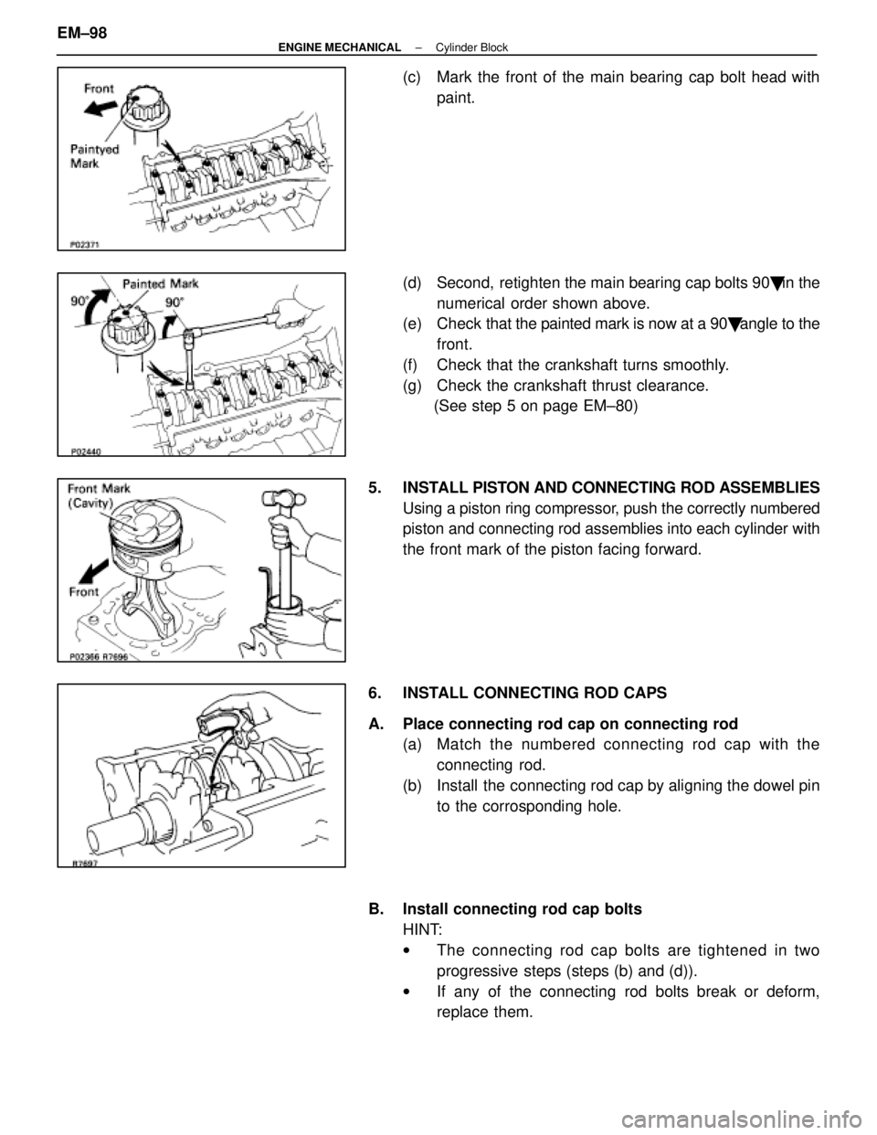
(c) Mark the front of the main bearing cap bolt head withpaint.
(d) Second, retighten the main bearing cap bolts 90 � in the
numerical order shown above.
(e) Check that the painted mark is now at a 90 � angle to the
front.
(f) Check that the crankshaft turns smoothly.
(g) Check the crankshaft thrust clearance. (See step 5 on page EM±80)
5. INSTALL PISTON AND CONNECTING ROD ASSEMBLIES Using a piston ring compressor, push the correctly numbered
piston and connecting rod assemblies into each cylinder with
the front mark of the piston facing forward.
6. INSTALL CONNECTING ROD CAPS
A. Place connecting rod cap on connecting rod (a) Match the numbered c onnecting rod cap with the
connecting rod.
(b) Install the connecting rod cap by aligning the dowel pin to the corrosponding hole.
B. Install connecting rod cap bolts HINT:
wThe connecting rod cap bolts are tightened in two
progressive steps (steps (b) and (d)).
w If any of the connecting rod bolts break or deform,
replace them.
EM±98
±
ENGINE MECHANICAL Cylinder Block
WhereEverybodyKnowsYourName
Page 1854 of 4087

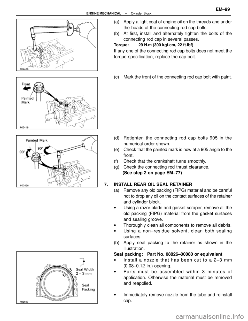
(a) Apply a light coat of engine oil on the threads and under
the heads of the connecting rod cap bolts.
(b) At first, install and alternately tighten the bolts of the connecting rod cap in several passes.
Torque: 29 N Vm (300 kgf Vcm, 22 ft Vlbf)
If any one of the connecting rod cap bolts does not meet the
torque specification, replace the cap bolt.
(c) Mark the front of the connecting rod cap bolt with paint.
(d) Retighten the connecting rod cap bolts 905 in the
numerical order shown.
(e) Check that the painted mark is now at a 905 angle to the
front.
(f) Check that the crankshaft turns smoothly.
(g) Check the connecting rod thrust clearance. (See step 2 on page EM±77)
7. INSTALL REAR OIL SEAL RETAINER (a) Remove any old packing (FIPG) material and be carefulnot to drop any oil on the contact surfaces of the retainer
and cylinder block.
w Using a razor blade and gasket scraper, remove all the
old packing (FIPG) material from the gasket surfaces
and sealing groove.
w Thoroughly clean all components to remove all debris.
w Using a non±residue solvent, clean both sealing
surfaces.
(b) Apply seal packing to the retainer as shown in the illustration.
Seal packing: Part No. 08826±00080 or equivalent
w Install a nozzle that has been cut to a 2±3 mm
(0.08±0.12 in.) opening.
w Parts must be assembled within 3 minutes of
application. Otherwise the material must be removed
and reapplied.
w Immediately remove nozzle from the tube and reinstall
cap.
±
ENGINE MECHANICAL Cylinder BlockEM±99
WhereEverybodyKnowsYourName
Page 1857 of 4087
14. (M/T)INSTALL FLYWHEEL
HINT: The flywheel bolts are tightened in two progressive
steps, (b) and (d).
(a) Install the flywheel on the crankshaft.
(b) Install and uniformly tighten the eight mount bolts inseveral passes in the sequence shown.
Torque: 49 N Vm (500 kgf Vcm, 36 ft Vlbf)
(c) Mark the flywheel bolt with paint.
(d) Second, retighten the flywheel bolts by an additional
90�.
(e) Check that the painted mark is now at a 90 � angle to (c).
15. (A/T) INSTALL DRIVE PLATE
(a) Apply adhesive to two or three threads of the mountingbolt end.
Adhesive: Part No. 08833±00070, THREE BOND 1324 or
equivalent
(b) Install the front spacer, drive plate and rear spacer on the crankshaft.
(c) Install and uniformly tighten the eight mounting bolts in
several passes in the sequence shown.
Torque: 98 N Vm (1,000 kgf Vcm, 72 ft Vlbf)
EM±102±
ENGINE MECHANICAL Cylinder Block
WhereEverybodyKnowsYourName
Page 1860 of 4087
HINT: Adjust the center support bearing to keep the intervals
as shown with the vehicle in the unladen condition.
Under the same condition, check if the center line of the cen-
ter support bearing is at right angles to the shaft axial direc-
tion.
(f) Inspect the joint angle. (See page PR±13)
3. (A/T) CONNECT TRANSMISSION CONTROL ROD
Connect the control rod to the shift lever with the nut.
4. INSTALL EXHAUST PIPE HEAT INSULATOR Install the heat insulator with the four nuts as shown.
5. INSTALL NO. 2 FRONT EXHAUST PIPE (a) Install new two gaskets and No. 2 front exhaust pipe with
new four nuts.
Torque: 62 N Vm (630 kgf Vcm, 46 ft Vlbf)
(b) Install a new gasket and the No. 2 front exhaust pipe to
the front exhaust pipe with the two bolts and nuts.
Torque: 43 N Vm (440 kgf Vcm, 32 ft Vlbf)
±
ENGINE MECHANICAL Cylinder BlockEM±105
WhereEverybodyKnowsYourName