Page 1719 of 4087
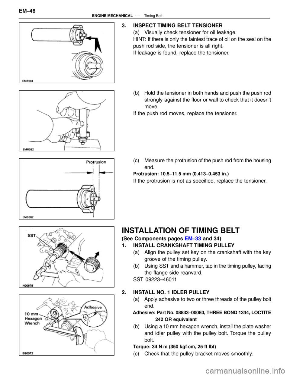
3. INSPECT TIMING BELT TENSIONER(a) Visually check tensioner for oil leakage.
HINT: If there is only the faintest trace of oil on the seal on the
push rod side, the tensioner is all right.
If leakage is found, replace the tensioner.
(b) Hold the tensioner in both hands and push the push rodstrongly against the floor or wall to check that it doesn't
move.
If the push rod moves, replace the tensioner.
(c) Measure the protrusion of the push rod from the housing
end.
Protrusion: 10.5±11.5 mm (0.413±0.453 in.)
If the protrusion is not as specified, replace the tensioner.
INSTALLATION OF TIMING BELT
(See Components pages EM±33 and 34)
1. INSTALL CRANKSHAFT TIMING PULLEY (a) Align the pulley set key on the crankshaft with the keygroove of the timing pulley.
(b) Using SST and a hammer, tap in the timing pulley, facing
the flange side rearward.
SST 09223±46011
2. INSTALL NO. 1 IDLER PULLEY (a) Apply adhesive to two or three threads of the pulley boltend.
Adhesive: Part No. 08833±00080, THREE BOND 1344, LOCTITE
242 OR equivalent
(b) Using a 10 mm hexagon wrench, install the plate washer
and idler pulley with the pulley bolt. Torque the pulley
bolt.
Torque: 34 N Vm (350 kgf Vcm, 25 ft Vlbf)
(c) Check that the pulley bracket moves smoothly.
EM±46
±
ENGINE MECHANICAL Timing Belt
WhereEverybodyKnowsYourName
Page 1720 of 4087
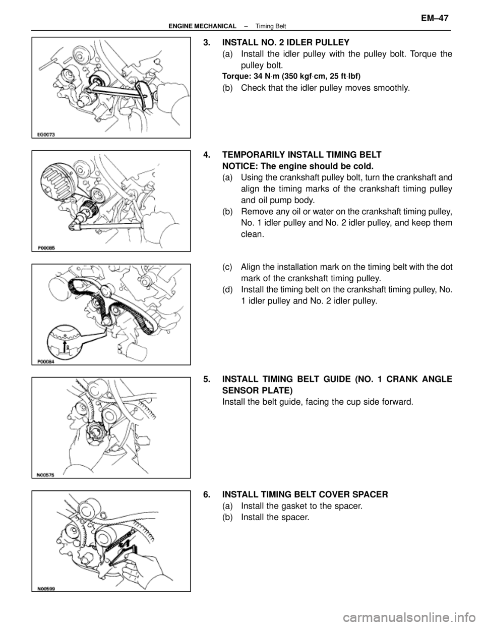
3. INSTALL NO. 2 IDLER PULLEY(a) Install the idler pulley with the pulley bolt. Torque thepulley bolt.
Torque: 34 N Vm (350 kgf Vcm, 25 ft Vlbf)
(b) Check that the idler pulley moves smoothly.
4. TEMPORARILY INSTALL TIMING BELT NOTICE: The engine should be cold.
(a) Using the crankshaft pulley bolt, turn the crankshaft andalign the timing marks of the crankshaft timing pulley
and oil pump body.
(b) Remove any oil or water on the crankshaft timing pulley,
No. 1 idler pulley and No. 2 idler pulley, and keep them
clean.
(c) Align the installation mark on the timing belt with the dot
mark of the crankshaft timing pulley.
(d) Install the timing belt on the crankshaft timing pulley, No.
1 idler pulley and No. 2 idler pulley.
5. INSTALL TIMING BELT GUIDE (NO. 1 CRANK ANGLE SENSOR PLATE)
Install the belt guide, facing the cup side forward.
6. INSTALL TIMING BELT COVER SPACER (a) Install the gasket to the spacer.
(b) Install the spacer.
±
ENGINE MECHANICAL Timing BeltEM±47
WhereEverybodyKnowsYourName
Page 1723 of 4087
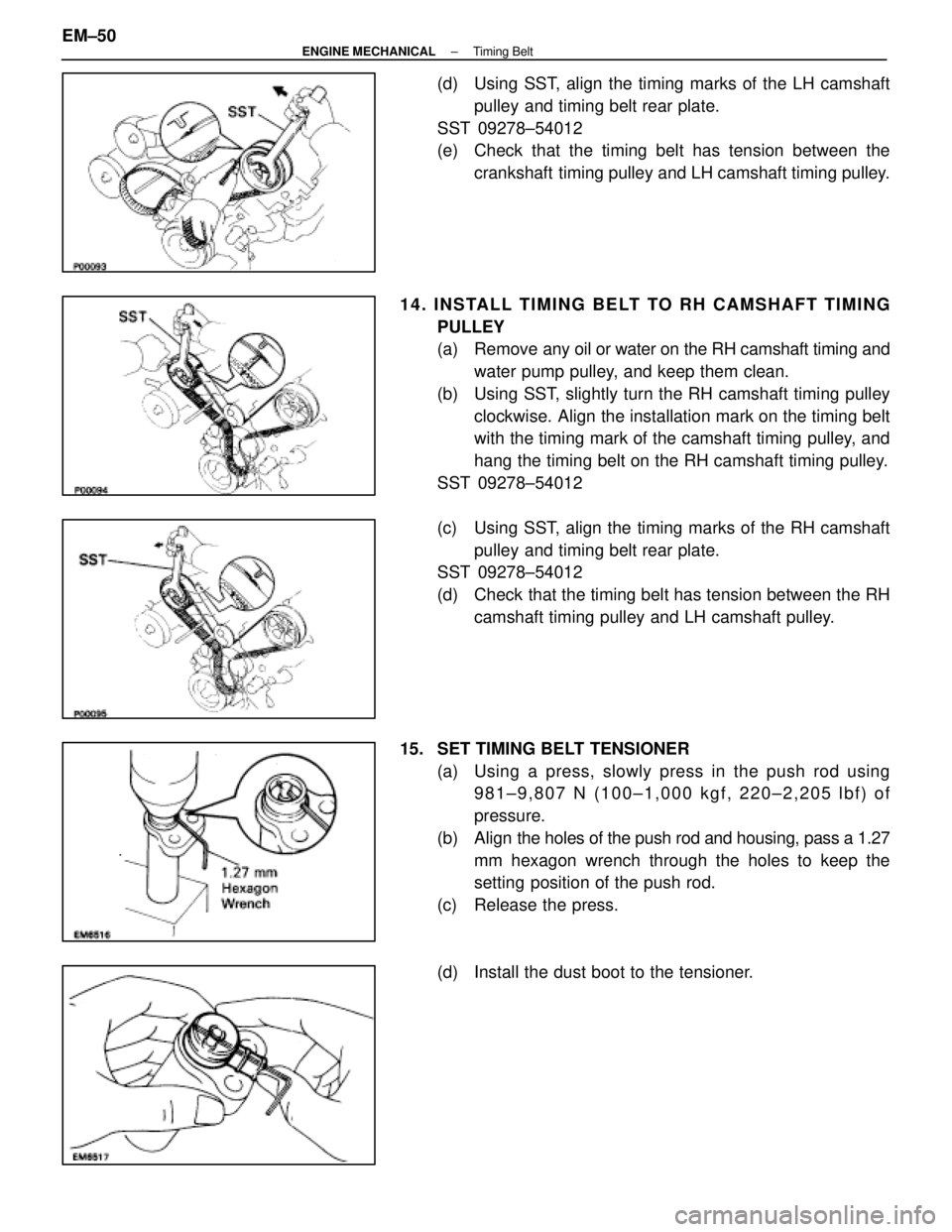
(d) Using SST, align the timing marks of the LH camshaftpulley and timing belt rear plate.
SST 09278±54012
(e) Check that the timing belt has tension between the crankshaft timing pulley and LH camshaft timing pulley.
14. INSTALL TIMING BELT TO RH CAMSHAFT TIMING PULLEY
(a) Remove any oil or water on the RH camshaft timing andwater pump pulley, and keep them clean.
(b) Using SST, slightly turn the RH camshaft timing pulley clockwise. Align the installation mark on the timing belt
with the timing mark of the camshaft timing pulley, and
hang the timing belt on the RH camshaft timing pulley.
SST 09278±54012
(c) Using SST, align the timing marks of the RH camshaft pulley and timing belt rear plate.
SST 09278±54012
(d) Check that the timing belt has tension between the RH
camshaft timing pulley and LH camshaft pulley.
15. SET TIMING BELT TENSIONER (a) Using a press, slowly press in the push rod using981±9,807 N (100±1,000 kgf, 220±2,205 lbf) of
pressure.
(b) Align the holes of the push rod and housing, pass a 1.27
mm hexagon wrench through the holes to keep the
setting position of the push rod.
(c) Release the press.
(d) Install the dust boot to the tensioner.
EM±50
±
ENGINE MECHANICAL Timing Belt
WhereEverybodyKnowsYourName
Page 1724 of 4087
16. INSTALL TIMING BELT TENSIONER(a) Temporarily install the tensioner with the two bolts.
(b) Alternately tighten the two bolts.
Torque: 26 N Vm (270 kgf Vcm, 20 ft Vlbf)
(c) Using pliers, remove the 1.27 mm hexagon wrench from
the tensioner.
17. CHECK VALVE TIMING (a) Turn the crankshaft pulley two revolutions from TDC toTDC.
NOTICE: Always turn the crankshaft clockwise.
(b) Check that each pulley aligns with the timing marks as shown in the figure.
If the marks do not align, remove the timing belt and reinstall
it.
18. INSTALL SPARK PLUGS Using a 16 mm plug wrench, install the eight spark plugs.
Torque: 18 N Vm (180 kgf Vcm, 13 ft Vlbf)
±
ENGINE MECHANICAL Timing BeltEM±51
WhereEverybodyKnowsYourName
Page 1730 of 4087
37. INSTALL A/C COMPRESSOR(a) In sta ll th e A/C co mp re sso r, co mp re sso r sta y an dground cable with the three bolts and nut.
Torque: Bolt 49 N Vm (500 kgf Vcm, 36 ft Vlbf)
Nut 29 N Vm (300 kgf Vcm, 22 ft Vlbf)
(b) Connect the A/C compressor connector.
38. INSTALL RADIATOR AND RESERVOIR TANK (See steps 25 and 26 on pages EM±174 to 175)
39. INSTALL DRIVE BELT Install the drive belt by turning the drive belt tensioner coun-
terclockwise.
HINT: The pully bolt for the belt tensioner has a lefthand
thread.
40. INSTALL BATTERY
41. FILL WITH ENGINE COOLANT (See page CO±7)
42. CHECK IGNITION TIMING (See page IG±28)
Ignition timing:
8±125 BTDC @ idle
(w/ Terminals TE1 and E1 connected)
43. INSTALL ENGINE UNDER COVER
±
ENGINE MECHANICAL Timing BeltEM±57
WhereEverybodyKnowsYourName
Page 1741 of 4087
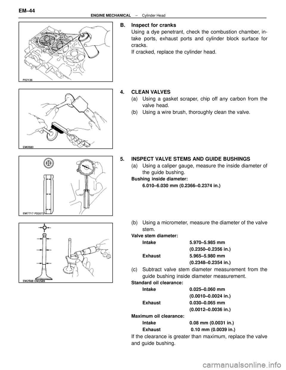
B. Inspect for cranksUsing a dye penetrant, check the combustion chamber, in-
take ports, exhaust ports and cylinder block surface for
cracks.
If cracked, replace the cylinder head.
4. CLEAN VALVES (a) Using a gasket scraper, chip off any carbon from thevalve head.
(b) Using a wire brush, thoroughly clean the valve.
5. INSPECT VALVE STEMS AND GUIDE BUSHINGS (a) Using a caliper gauge, measure the inside diameter ofthe guide bushing.
Bushing inside diameter:
6.010±6.030 mm (0.2366±0.2374 in.)
(b) Using a micrometer, measure the diameter of the valvestem.
Valve stem diameter:
Intake 5.970±5.985 mm (0.2350±0.2356 in.)
Exhaust 5.965±5.980 mm (0.2348±0.2354 in.)
(c) Subtract valve stem diameter measurement from theguide bushing inside diameter measurement.
Standard oil clearance:
Intake 0.025±0.060 mm
(0.0010±0.0024 in.)
Exhaust 0.030±0.065 mm (0.0012±0.0036 in.)
Maximum oil clearance:
Intake 0.08 mm (0.0031 in.)
Exhaust 0.10 mm (0.0039 in.)
If the clearance is greater than maximum, replace the valve
and guide bushing.
EM±44
±
ENGINE MECHANICAL Cylinder Head
WhereEverybodyKnowsYourName
Page 1743 of 4087
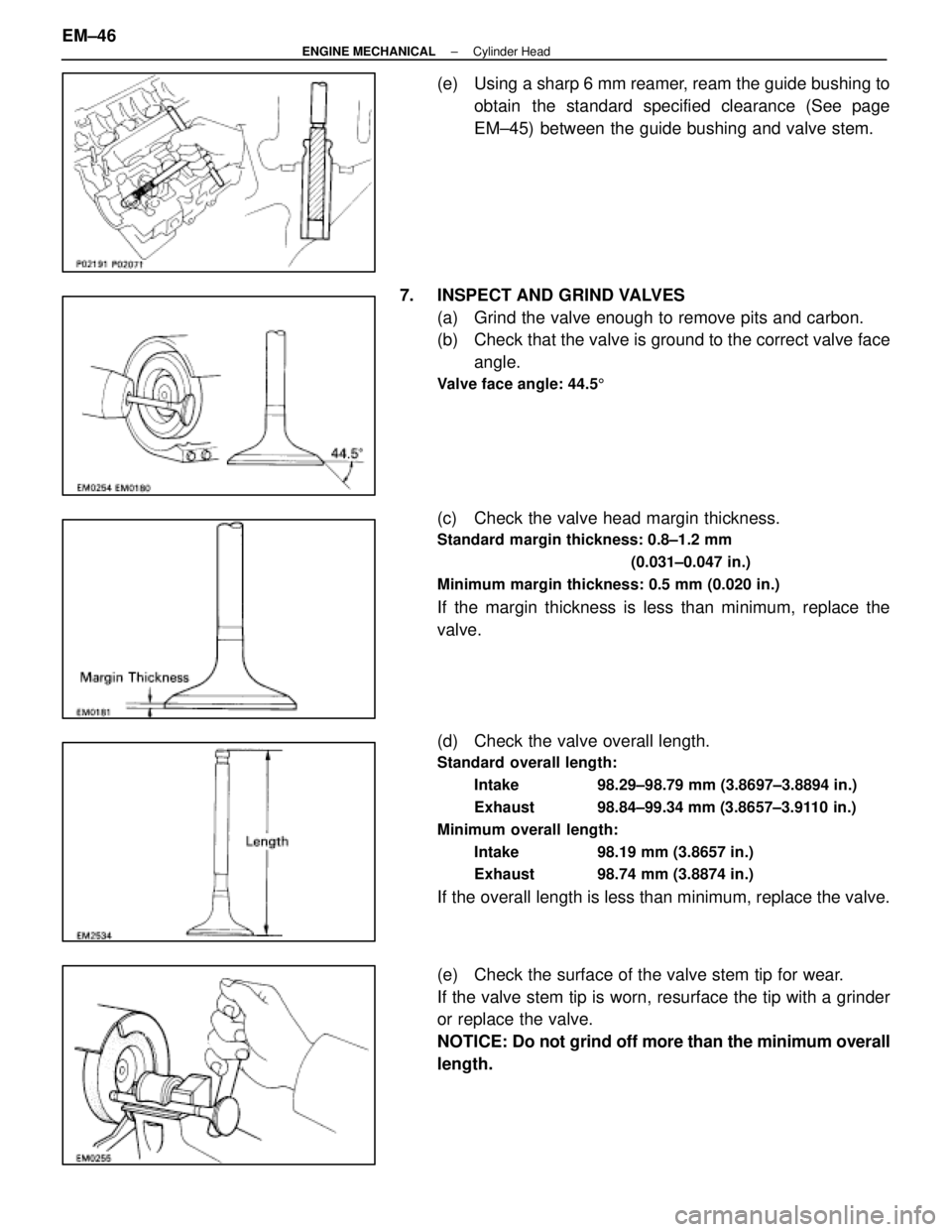
(e) Using a sharp 6 mm reamer, ream the guide bushing toobtain the standard specified clearance (See page
EM±45) between the guide bushing and valve stem.
7. INSPECT AND GRIND VALVES (a) Grind the valve enough to remove pits and carbon.
(b) Check that the valve is ground to the correct valve faceangle.
Valve face angle: 44.5 5
(c) Check the valve head margin thickness.
Standard margin thickness: 0.8±1.2 mm
(0.031±0.047 in.)
Minimum margin thickness: 0.5 mm (0.020 in.)
If the margin thickness is less than minimum, replace the
valve.
(d) Check the valve overall length.
Standard overall length: Intake 98.29±98.79 mm (3.8697±3.8894 in.)
Exhaust 98.84±99.34 mm (3.8657±3.9110 in.)
Minimum overall length: Intake 98.19 mm (3.8657 in.)
Exhaust 98.74 mm (3.8874 in.)
If the overall length is less than minimum, replace the valve.
(e) Check the surface of the valve stem tip for wear.
If the valve stem tip is worn, resurface the tip with a grinder
or replace the valve.
NOTICE: Do not grind off more than the minimum overall
length.
EM±46
±
ENGINE MECHANICAL Cylinder Head
WhereEverybodyKnowsYourName
Page 1744 of 4087
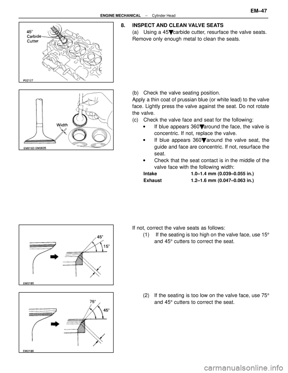
8. INSPECT AND CLEAN VALVE SEATS(a) Using a 45 � carbide cutter, resurface the valve seats.
Remove only enough metal to clean the seats.
(b) Check the valve seating position.
Apply a thin coat of prussian blue (or white lead) to the valve
face. Lightly press the valve against the seat. Do not rotate
the valve.
(c) Check the valve face and seat for the following: w If blue appears 360 � around the face, the valve is
concentric. If not, replace the valve.
w If blue appears 360 � around the valve seat, the
guide and face are concentric. If not, resurface the
seat.
w Check that the seat contact is in the middle of the
valve face with the following width:
Intake 1.0±1.4 mm (0.039±0.055 in.)
Exhaust 1.2±1.6 mm (0.047±0.063 in.)
If not, correct the valve seats as follows:
(1) If the seating is too high on the valve face, use 15 5
and 45 5 cutters to correct the seat.
(2) If the seating is too low on the valve face, use 75 5
and 45 5 cutters to correct the seat.
±
ENGINE MECHANICAL Cylinder HeadEM±47
WhereEverybodyKnowsYourName