Page 977 of 1640
Outline
Description
This engine is a 2,977 cm3 (181.6 cu-in) DOHC mid-ship unit having 6 cylinders of 90° —V configuration; it is water cool-
ed and equipped with a center plug type pent roof combustion chamber. It is specified for unleaded fuel and uses a
PGM-FI system: The PGM-FI system on this model is a sequential multiport fuel injection system.
PGM-FI system. This engine incorporates a new mechanism called Honda Variable Valve Timing and Valve Lift Elec-
tronic Control System (VTEC). This mechanism, the world's first, allows the timing and lift of the intake and exhaust
valves to be changed simultaneously. The engine also includes a new electronically-controlled intake manifold system
that can change the volume of the intake chamber.ProCarManuals.com
Page 978 of 1640
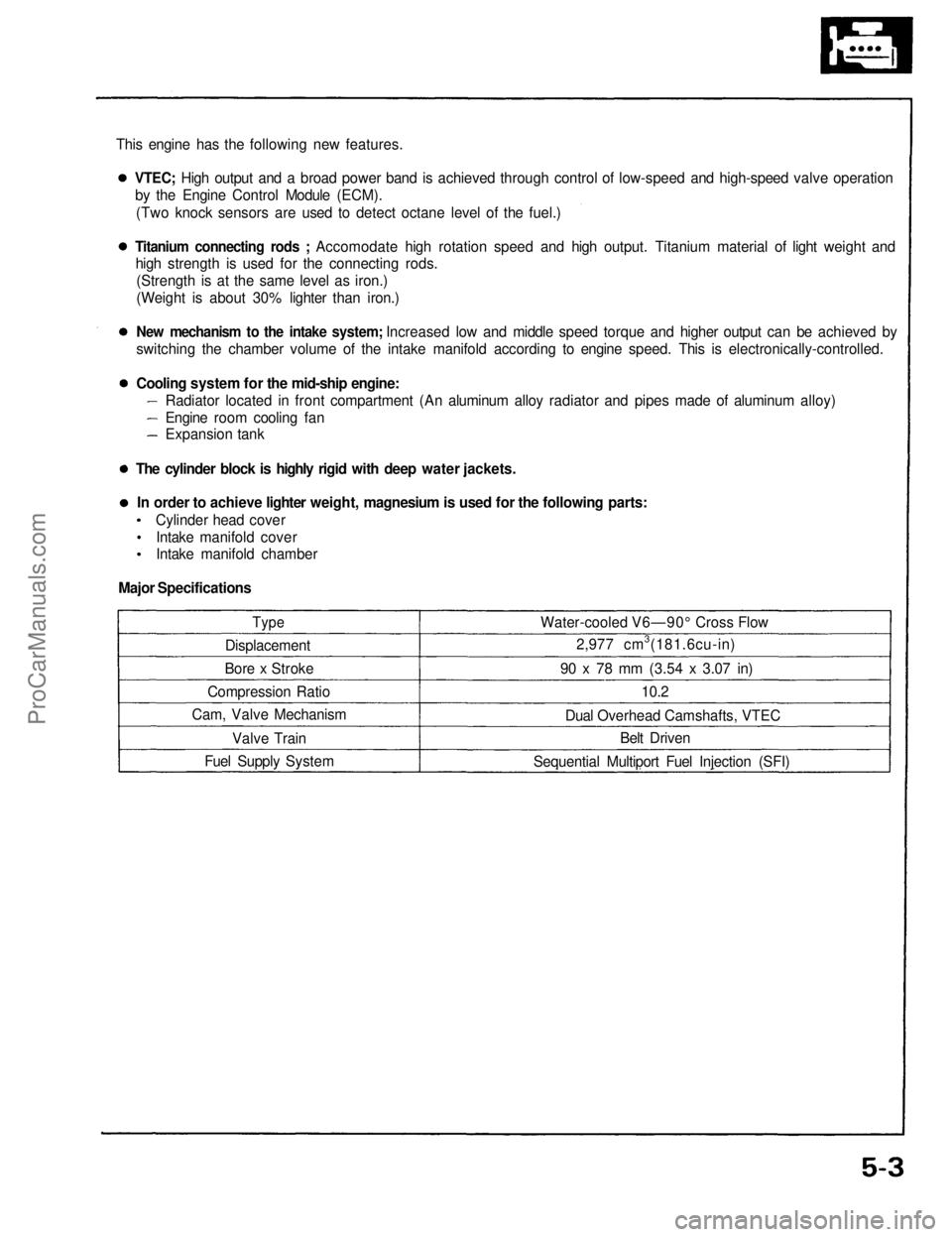
This engine has the following new features.
Type
Displacement
Bore x Stroke
Compression Ratio
Cam, Valve Mechanism
Valve Train
Fuel Supply System Water-cooled V6—90° Cross Flow
2,977 cm3(181.6cu-in)
90 x 78 mm
(3.54
x
3.07
in)
10.2
Dual Overhead Camshafts, VTEC Belt Driven
Sequential Multiport Fuel Injection (SFI)VTEC; High output and a broad power band is achieved through control of low-speed and high-speed valve operation
by the Engine Control Module (ECM).
(Two knock sensors are used to detect octane level of the fuel.)
Titanium connecting rods ; Accomodate high rotation speed and high output. Titanium material of light weight and
high strength is used for the connecting rods.
(Strength is at the same level as iron.)
(Weight is about 30% lighter than iron.)
New mechanism to the intake system; Increased low and middle speed torque and higher output can be achieved by
switching the chamber volume of the intake manifold according to engine speed. This is electronically-controlled.
Cooling system for the mid-ship engine:
Radiator located in front compartment (An aluminum alloy radiator and pipes made of aluminum alloy)
Engine room cooling fan
Expansion tank
The cylinder block is highly rigid with deep water jackets. In order to achieve lighter weight, magnesium is used for the following parts: Cylinder head coverIntake manifold cover
Intake manifold chamber
Major SpecificationsProCarManuals.com
Page 987 of 1640
Engine Removal/Installation
(cont'd)
10. Disconnect the resistor connector and fan motor connector, then remove the engine room fan
assembly.
ENGINE ROOM
FAN
ENGINE ROOM
FAN CONNECTOR
GROMMET
11. Remove the rear trim panels behind the
passenger's seat, then disconnect four connectors
from Engine Control Module (ECM) and five con- nectors from floor wire harness.
ENGINE WIRE
HARNESS CONNECTORS
ECM
PASSENGER'S
SEAT
FLOOR WIRE HARNESS
ENGINE WIRE
HARNESS
FUEL PUMP RESISTOR
CONNECTORGROUND
CABLE
6x1.0
mm
10 N.m (1.0 kg-m, 7 Ib-ft)
CORROSION RESISTANT BOLT
6 x 1.0 mm
10 N.m d.Okg.m, 7 Ib-ft)ProCarManuals.com
Page 988 of 1640
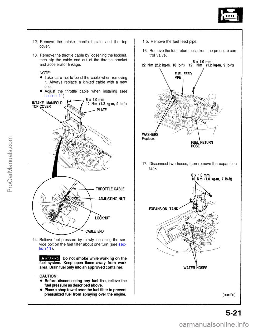
12. Remove the intake manifold plate and the top
cover.
13. Remove the throttle cable by loosening the locknut, then slip the cable end out of the throttle bracketand accelerator linkage.
INTAKE MANIFOLD
TOP COVER
6 x 1.0 mm
12 N .
m (1.2 kg-m, 9 Ib-ft)
PLATE
ADJUSTING NUT
LOCKNUT
CABLE END
14. Relieve fuel pressure by slowly loosening the ser-
vice bolt on the fuel filter about one turn (see sec-
tion 11 ).
1 5. Remove the fuel feed pipe.
16. Remove the fuel return hose from the pressure con- trol valve.
6 x 1.0 mm
22 N .
m (2.2 kg-m. 16 Ib-ft) 12 N .
m (1.2 kg-m, 9 Ib-ft)
FUEL FEED
PIPE
WASHERS
Replace.
FUEL RETURN
HOSE
17. Disconnect two hoses, then remove the expansion tank.
6 x 1.0 mm
10 N .
m (1.0 kg-m, 7 Ib-ft)
EXPANSION TANK
WATER HOSES
(cont'd)
Do not smoke while working on the
fuel system. Keep open flame away from work
area. Drain fuel only into an approved container.
CAUTION:
THROTTLE CABLE
NOTE:
Take care not to bend the cable when removingit. Always replace a kinked cable with a new
one.
Adjust the throttle cable when installing (see
section 11).
Before disconnecting any fuel line, relieve the
fuel pressure as described above.
Place a shop towel over the fuel filter to prevent
pressurized fuel from spraying over the engine.ProCarManuals.com
Page 998 of 1640
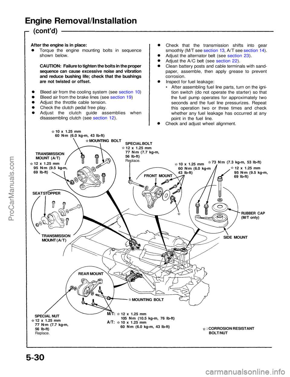
Engine Removal/Installation
(cont'd)
Torque the engine mounting bolts in sequenceshown below.
CAUTION: Failure to tighten the bolts in the proper
sequence can cause excessive noise and vibration
and reduce bushing life; check that the bushings
are not twisted or offset.
Bleed air from the cooling system (see section 10)
Bleed air from the brake lines (see section 19)
Adjust the throttle cable tension.
Check the clutch pedal free play.
Adjust the clutch guide assemblies when
disassembling clutch (see section 12). Check that the transmission shifts into gear
smoothly (M/T see section 13, A/T see section 14).
Adjust the alternator belt (see section 23).
Adjust the A/C belt (see section 22).
Clean battery posts and cable terminals with sand-
paper, assemble, then apply grease to prevent
corrosion.
Inspect for fuel leakage:
• After assembling fuel line parts, turn on the igni- tion switch (do not operate the starter) so that
the fuel pump operates for approximately two seconds and the fuel line pressurizes. Repeat
this operation two or three times and check whether any fuel leakage has occurred at any
point in the fuel line.
Check and adjust wheel alignment.
10 x
1.25
mm
60 N .
m (6.0 kg-m, 43 Ib-ft)
MOUNTING BOLT SPECIAL BOLT
12 x
1.25
mm
77 N .
m
(7.7 kg-m,
56 Ib-ft)
Replace.
10 x
1.25
mm
60 N .
m
(6.0 kg-m
43 Ib-ft) 73 N.m (7.3 kg-m, 53 Ib-ft)
12 x
1.25
mm
95 N .
m
(9.5 kg-m,
69 Ib-ft)
RUBBER CAP
(M/T only)
SIDE MOUNT
: CORROSION RESISTANT
BOLT/NUT
12 x
1.25
mm
105 N .
m (10.5 kg-m, 76 Ib-ft)
10 x
1.25
mm
60 N .
m (6.0 kg-m, 43 Ib-ft) MOUNTING BOLT FRONT MOUNT
TRANSMISSION
MOUNT (A/T)
12 x
1.25
mm
95 N .
m
(9.5 kg-m,
69 Ib-ft)
SEAT STOPPER
TRANSMISSION
MOUNT (A/T)
REAR MOUNT
SPECIAL NUT
12 x
1.25
mm
77 N .
m
(7.7 kg-m,
56 Ib-ft)
Replace.
M/T:
A/T:
After the engine is in place:ProCarManuals.com
Page 1015 of 1640
14. Relieve fuel pressure (see section 11).
Do not smoke while working on fuel
system; keep open flame or spark away from work
area. Drain fuel only into an approved container.
1 5. Disconnect the fuel feed pipe and the return hose
(page 5-21).
16. Remove the ignition coil covers, the wire harness covers, the ignition coils and the connectors (page
6-23).
17. Remove the water hoses, then remove the expan- sion tank (page 5-21).
18. Remove the breather hose, and the air cleaner housing (page 5-22).
19. Remove the brake booster hose, the evaporative emission (EVAP) control canister hose and other
hoses from the intake manifold and throttle body
(page 5-22).
20. Remove the emission control box (page 5-23). Do not disconnect emission hose.Disconnect the three connectors before
removing.
21. Remove the connector, the terminal and the alternator.
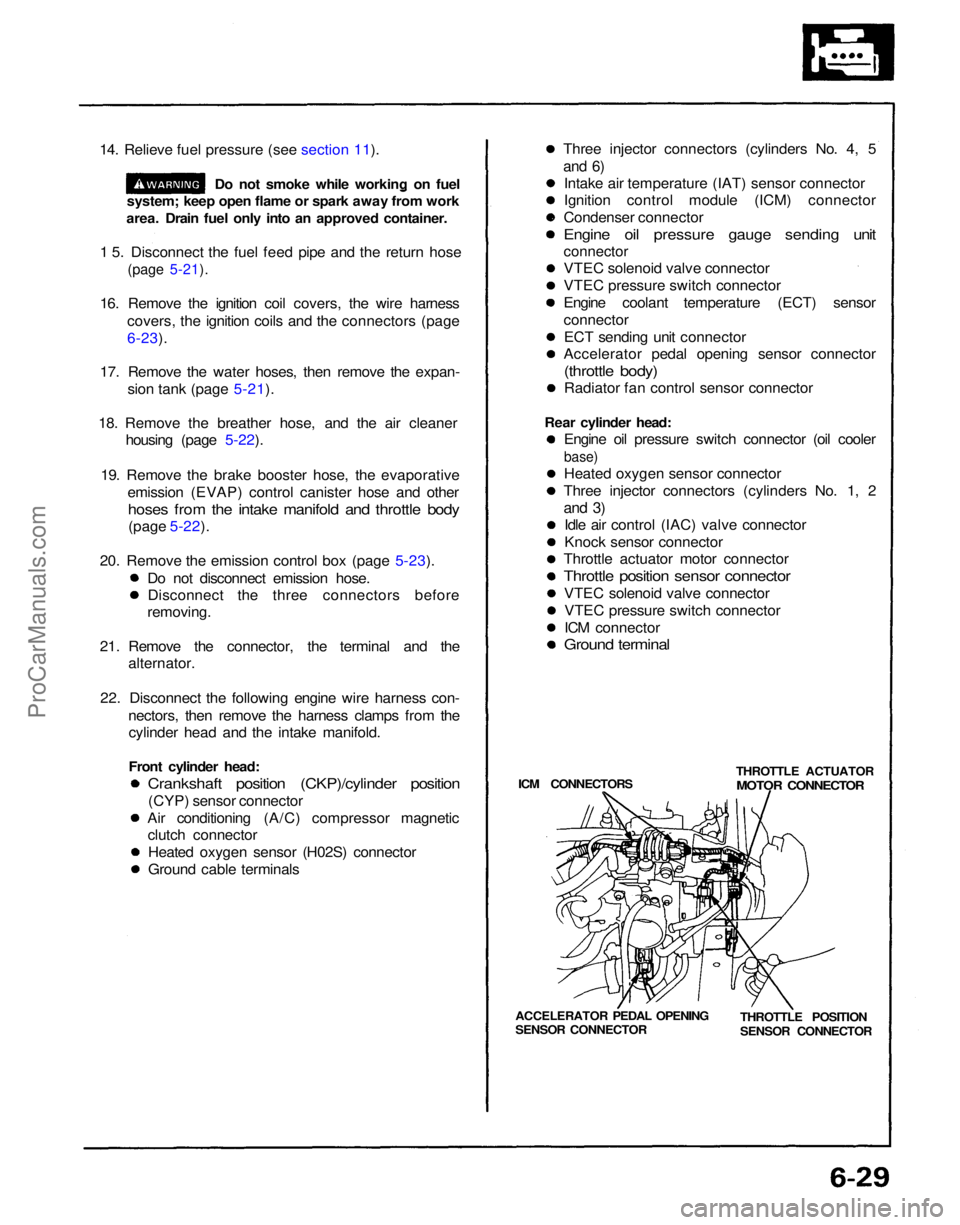
22. Disconnect the following engine wire harness con- nectors, then remove the harness clamps from thecylinder head and the intake manifold.
Front cylinder head:
Crankshaft position (CKP)/cylinder position
(CYP) sensor connector
Air conditioning (A/C) compressor magnetic clutch connector
Heated oxygen sensor (H02S) connector
Ground cable terminals Three injector connectors (cylinders No. 4, 5
and 6)
Intake air temperature (IAT) sensor connector
Ignition control module (ICM) connector
Condenser connector
Engine oil pressure gauge sending unit
connector
VTEC solenoid valve connector
VTEC pressure switch connector
Engine coolant temperature (ECT) sensor
connector
ECT sending unit connector
Accelerator pedal opening sensor connector
(throttle body)
Radiator fan control sensor connector
Rear cylinder head: Engine oil pressure switch connector (oil cooler
base)
Heated oxygen sensor connector
Three injector connectors (cylinders No. 1, 2
and 3)
Idle air control (IAC) valve connector
Knock sensor connector
Throttle actuator motor connector
Throttle position sensor connector
VTEC solenoid valve connectorVTEC pressure switch connector
ICM connector
Ground terminal
ICM CONNECTORS THROTTLE ACTUATOR
MOTOR CONNECTOR
THROTTLE POSITION
SENSOR CONNECTOR
ACCELERATOR PEDAL OPENING
SENSOR CONNECTORProCarManuals.com
Page 1048 of 1640
Special Tools
Ref. No.
Tool Number
A973X-041 -XXXXX
KS-AHM-32-003
07LAJ-PT3010A
07MAJ-PR70100
07JAZ-001000A
07406-0040001
Page Reference
11-62,116,
131,135,137,
146,148,154
11-37,50,55
11-37
11-37
11-156,157
11-106,113
Description
Vacuum Pump/Gauge
Digital Multimeter
Test Harness
Test Harness Vacuum/Pressure Gauge 0—4 in. Hg
Fuel Pressure Gauge
Qty
1
1
1
1
1
1ProCarManuals.com
Page 1049 of 1640
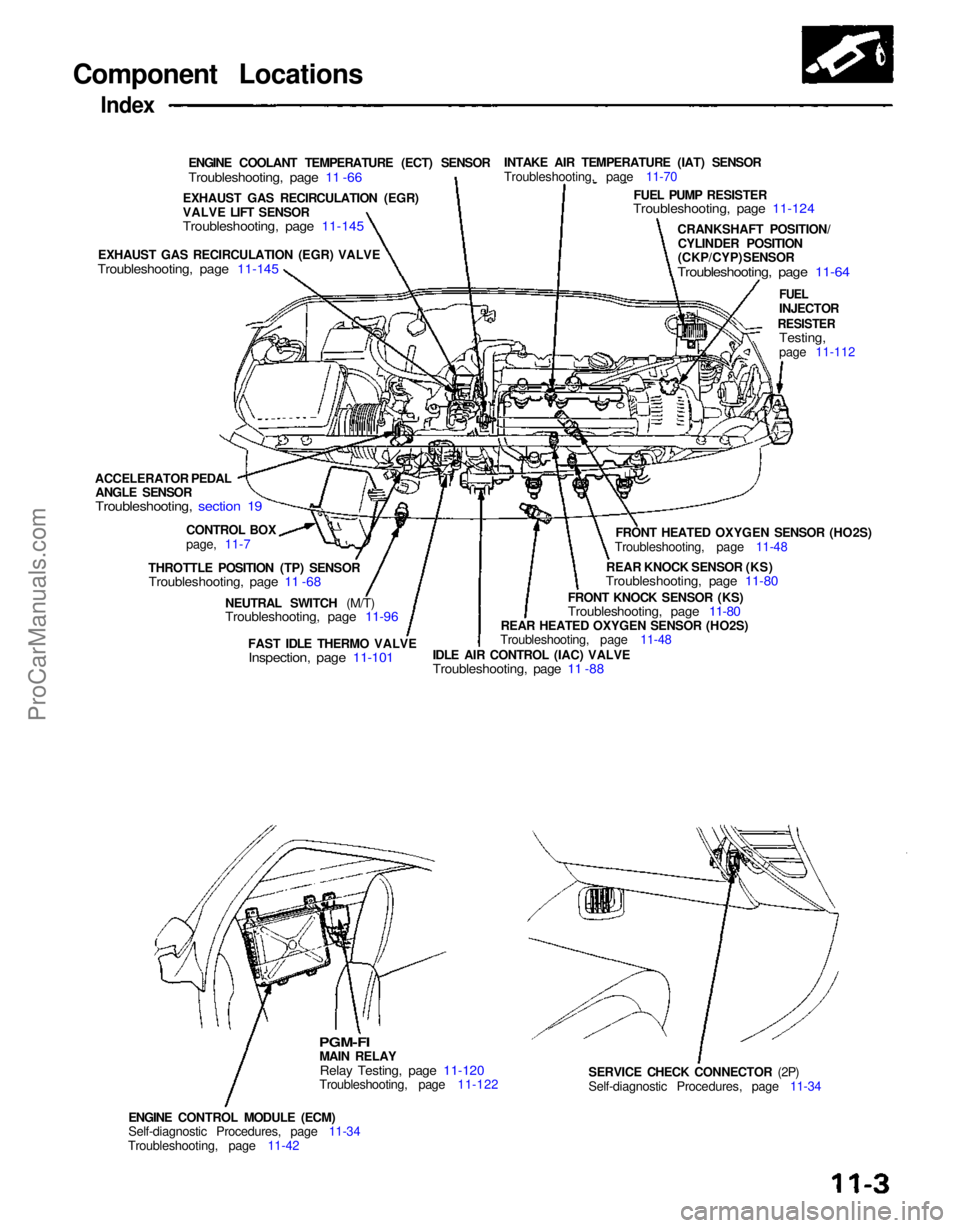
Component Locations
Index
ENGINE COOLANT TEMPERATURE (ECT) SENSOR
Troubleshooting, page 11 -66
INTAKE AIR TEMPERATURE (IAT) SENSOR
Troubleshooting, page 11-70
FUEL PUMP RESISTER
Troubleshooting, page 11-124
CRANKSHAFT POSITION/CYLINDER POSITION
(CKP/CYP) SENSOR
Troubleshooting, page 11-64
FUEL
INJECTOR
RESISTER
Testing,
page 11-112
FRONT HEATED OXYGEN SENSOR (HO2S)
Troubleshooting, page 11-48
REAR KNOCK SENSOR (KS)
Troubleshooting, page 11-80
FRONT KNOCK SENSOR (KS)
Troubleshooting, page 11-80
REAR HEATED OXYGEN SENSOR (HO2S)
Troubleshooting, page 11-48
IDLE AIR CONTROL (IAC) VALVE
Troubleshooting, page 11 -88
FAST IDLE THERMO VALVE
Inspection, page 11-101
NEUTRAL SWITCH (M/T)
Troubleshooting, page 11-96
SERVICE CHECK CONNECTOR (2P)
Self-diagnostic Procedures, page 11-34
ENGINE CONTROL MODULE (ECM)
Self-diagnostic Procedures, page 11-34
Troubleshooting, page 11-42
PGM-FI
MAIN RELAY
Relay Testing, page 11-120
Troubleshooting, page 11-122
THROTTLE POSITION (TP) SENSOR
Troubleshooting, page 11 -68
CONTROL BOX
page, 11-7
ACCELERATOR PEDAL
ANGLE SENSOR
Troubleshooting, section 19
EXHAUST GAS RECIRCULATION (EGR) VALVE
Troubleshooting, page 11-145
EXHAUST GAS RECIRCULATION (EGR)
VALVE LIFT SENSOR
Troubleshooting, page 11-145ProCarManuals.com