Page 267 of 1640

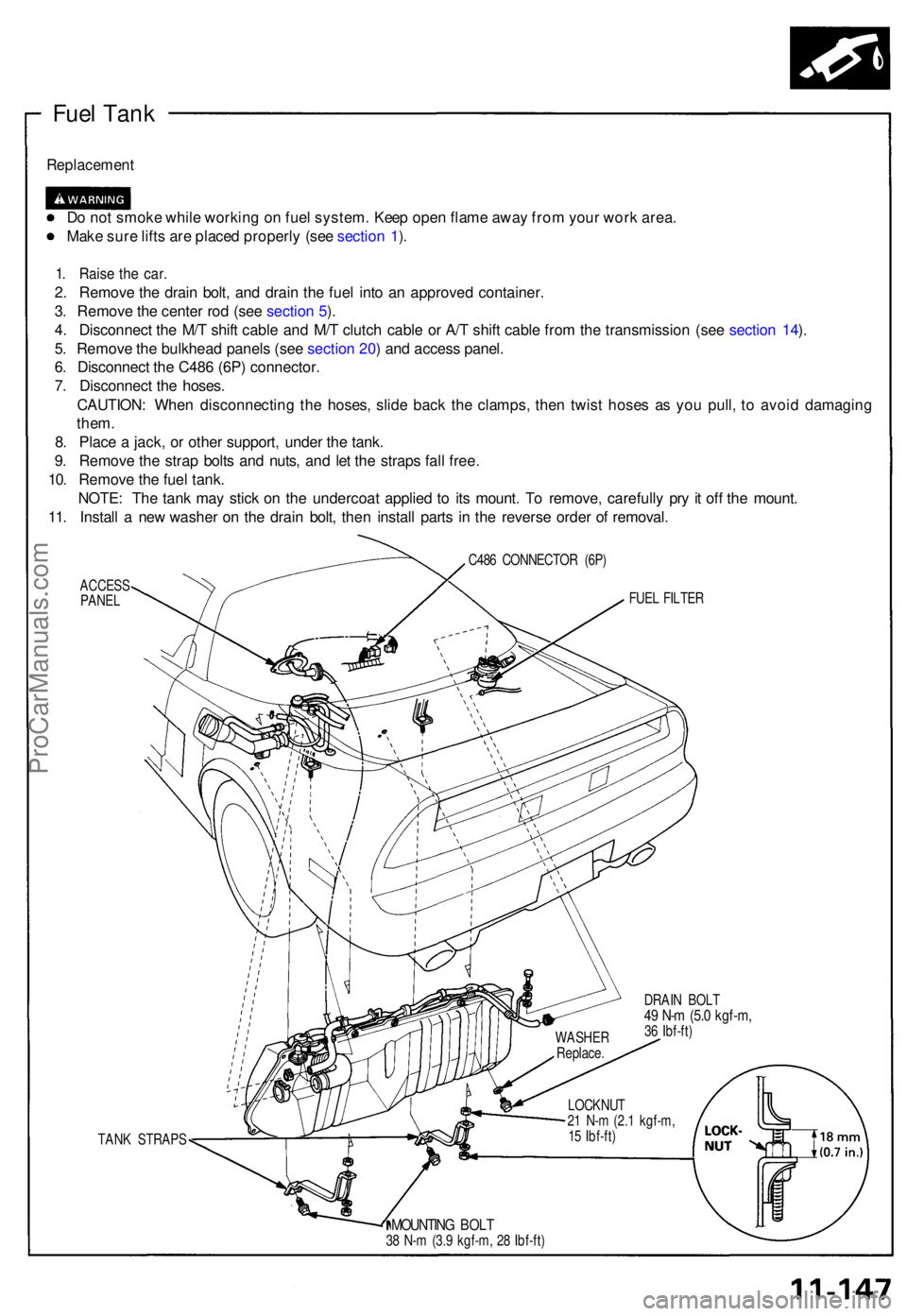
Fuel Tan k
Replacemen t
Do no t smok e whil e workin g o n fue l system . Kee p ope n flam e awa y fro m you r wor k area .
Mak e sur e lift s ar e place d properl y (se e sectio n 1 ).
1 . Rais e th e car .
2. Remov e th e drai n bolt , an d drai n th e fue l int o a n approve d container .
3 . Remov e th e cente r ro d (se e sectio n 5 ).
4 . Disconnec t th e M/ T shif t cabl e an d M/ T clutc h cabl e o r A/ T shif t cabl e fro m th e transmissio n (se e sectio n 14 ).
5 . Remov e th e bulkhea d panel s (se e se ctio n 20 ) an d acces s panel .
6 . Disconnec t th e C48 6 (6P ) connector .
7 . Disconnec t th e hoses .
CAUTION : Whe n disconnectin g th e hoses , slid e bac k th e clamps , the n twis t hose s a s yo u pull , t o avoi d damagin g
them .
8 . Plac e a jack , o r othe r support , unde r th e tank .
9 . Remov e th e stra p bolt s an d nuts , an d le t th e strap s fal l free .
10 . Remov e th e fue l tank .
NOTE : Th e tan k ma y stic k o n th e undercoa t applie d t o it s mount . T o remove , carefull y pr y i t of f th e mount .
11 . Instal l a ne w washe r o n th e drai n bolt , the n instal l part s i n th e revers e orde r o f removal .
C486 CONNECTO R (6P )
ACCES S
PANE L
TAN K STRAP S FUE
L FILTE R
DRAI N BOL T
49 N- m (5. 0 kgf-m ,36 Ibf-ft )
LOCKNU T
2 1 N- m (2. 1 kgf-m ,
1 5 Ibf-ft )
MOUNTIN G BOL T38 N- m (3. 9 kgf-m , 2 8 Ibf-ft )WASHE
R
Replace .
ProCarManuals.com
Page 273 of 1640
Fuel Injection Air (FIA) Control System
Description
The Fuel Injection Air (FIA) Control system enables fresh air to be drawn through the throttle body and fuel injector port.
IDLE ADJUSTING
SCREW
THROTTLE
BODY
FUEL INJECTOR
AIR FLOWProCarManuals.com
Page 280 of 1640

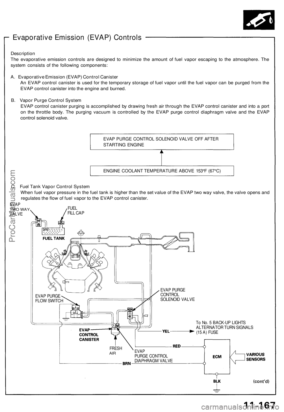
Evaporative Emission (EVAP) Controls
Description
The evaporative emission controls are designed to minimize the amount of fuel vapor escaping to the atmosphere. The
system consists of the following components:
A. Evaporative Emission (EVAP) Control Canister
An EVAP control canister is used for the temporary storage of fuel vapor until the fuel vapor can be purged from the
EVAP control canister into the engine and burned.
B. Vapor Purge Control System
EVAP control canister purging is accomplished by drawing fresh air through the EVAP control canister and into a port
on the throttle body. The purging vacuum is controlled by the EVAP purge control diaphragm valve and the EVAP
control solenoid valve.
EVAP PURGE CONTROL SOLENOID VALVE OFF AFTER
STARTING ENGINE
ENGINE COOLANT TEMPERATURE ABOVE 153°F (67°C)
To No. 5 BACK-UP LIGHTS
ALTERNATOR TURN SIGNALS
(15 A) FUSE
FRESH
AIR
EVAP
PURGE CONTROL
DIAPHRAGM VALVE
EVAP PURGE
CONTROL
SOLENOID VALVE
EVAP PURGE
FLOW SWITCH
C. Fuel Tank Vapor Control System
When fuel vapor pressure in the fuel tank is higher than the set value of the EVAP two way valve, the valve opens and
regulates the flow of fuel vapor to the EVAP control canister.
EVAP
TWO WAY
VALVE
FUEL
FILL CAPProCarManuals.com
Page 407 of 1640
Electrical Power Steering (EPS)
Outline
The NSX/NSX-T uses an electric motor-driven power steering, which possesses the characteristics best suited for a mid-
engine automobile. This system is a power-assisted steering device, with a motor inside the steering gearbox driven by
the EPS control unit. Its distinctive features are described below:
• Minimized loss of engine horsepower and decreased fuel consumption.
• A linear steering feel and the reduction of kickback.
• The system is compact and lightweight because it requires no complicated hydraulic piping, etc.
ALTERNATOR
TRANSMISSION
CONTROL MODULE (TCM)
EPS CONTROL UNIT
VEHICLE
SPEED SENSOR
PULSE UNIT (MT)
BATTERY
STEERING GEARBOX
STEERING WHEEL
STEERING
COLUMNProCarManuals.com
Page 563 of 1640
Types and Materials of Exterior Resin Parts
NOTE: A standard symbol is stamped on the underside of each resin part to show the type of material used.
Example:
HONDA
>PP<
NO.
Part Name
Headlight lid
Front bumper
Front and rear skirts
Mirror
Side sill panel
Trunk ltd spoiler
Rear bumper
Fuel filler lid
Washer Tank
Replacement
see section 23
see page 20-58('93-'96) ,47('91-'92)
see pages 20-59 ('93-'96),48 ('91-'92),
61('93-'96),50('91-'92)
see page 20-20('93-96) ,19('91-'92)
see page 20-71
see page 20-66('93-'96),55('91-'92)
see page 20-60('93-'96),49('91-'92)
see page 20-68('93-'96),57('91-'92)
see page 20-59('93-'96),48('91-'92)
Material
PA6/PPE-M Polyamide/Polyphenylene ether
PBT-P Polybutylene terephthalate
PP Polypropylene
ABS Acrylonitrite butadiene styrene
PA6/PPE-M Polyamide/Polyphenylene ether
UP-G Polyster unsaturated thermoset
PBT-P Polybutylene terephthalate
PA6/PP-E Polyamide/Polyphenylene ether
PP PolypropyleneProCarManuals.com
Page 624 of 1640

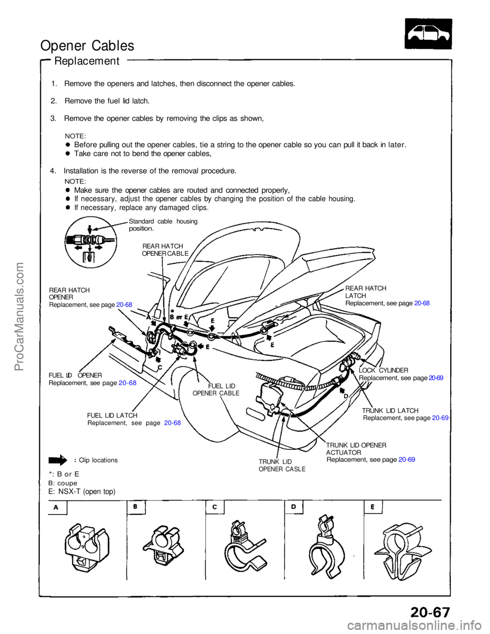
Opener Cables
Replacement
1. Remove the openers and latches, then disconnect the opener cables.
2. Remove the fuel lid latch.
3. Remove the opener cables by removing the clips as shown,
NOTE:
Before pulling out the opener cables, tie a string to the opener cable so you can pull it back in later. Take care not to bend the opener cables,
4. Installation is the reverse of the removal procedure.
NOTE:
Make sure the opener cables are routed and connected properly,
If necessary, adjust the opener cables by changing the position of the cable housing.
If necessary, replace any damaged clips.
Standard cable housing
position.
REAR HATCH
OPENER CABLE
REAR HATCH
OPENER
Replacement, see page 20-68
FUEL LID OPENER
Replacement, see page 20-68
FUEL LID
OPENER CABLE
FUEL LID LATCH
Replacement, see page 20-68
Clip locations
*: B or E
B: coupe
E: NSX-T (open top)
TRUNK LID
OPENER CASLE
TRUNK LID OPENER
ACTUATOR
Replacement, see page 20-69
TRUNK LID LATCH
Replacement, see page 20-69
LOCK CYLINDER
Replacement, see page 20-69
REAR HATCH
LATCH
Replacement, see page 20-68
ProCarManuals.com
Page 625 of 1640

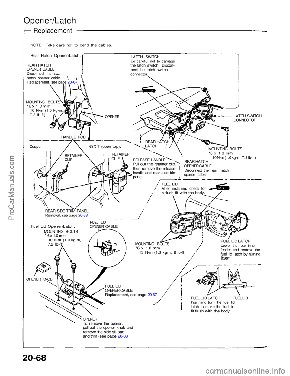
Opener/Latch
Replacement
NOTE: Take care not to bend the cables.
Rear Hatch Opener/Latch:
REAR HATCH
OPENER CABLE
Disconnect the rear
hatch opener cable.
Replacement, see page 20-67
MOUNTING BOLTS
* 6 x 1.0 mm
10 N·m
(1.0 kg-m,
7.2 Ib-ft)
OPENER
HANDLE ROD
Coupe:
RETAINER
CLIP
NSX-T (open top):
RETAINER
CLIP
REAR HATCH
LATCH
LATCH SWITCH
Be careful not to damage
the latch switch. Discon-
nect the latch switch
connector.
LATCH SWITCH
CONNECTOR
MOUNTING BOLTS
*6 x 1.0 mm
10 N·m (1.0 kg-m, 7.2 lb-ft)
REAR HATCH
OPENER CABLE
Disconnect the rear hatch
opener cable.
RELEASE HANDLE
Pull out the retainer clip.
then remove the release
handle and rear aide trim
panel.
FUEL LID
After installing, check tor
a flush fit with the body.
REAR SIDE TRIM PANEL
Removal
,
see page 20-38
Fuel Lid Opener/Latch:
MOUNTING BOLTS
* 6 x 1.0 mm
10 N·m
(1.0 kg-m,
7.2 Ib-ft)
FUEL LID
OPENER CABLE
MOUNTING BOLTS
*6 x 1.0 mm
13 N·m (1.3 kgm, 9 lb-ft)
FUEL LID LATCH
Lower the rear inner
fender and remove the
fuel lid latch by turning
it
90°.
FUEL LID LATCH
Push and turn the fuel lid
latch to make the fuel lid
fit flush with the body.
FUEL LID
FUEL LID
OPENER CABLE
Replacement, see page 20-67
OPENER
To remove the opener,
pull out the opener knob and
remove the side sill pad
and trim (see page 20-38
OPENER KNOBProCarManuals.com
Page 736 of 1640
RETRACTABLE HEADLIGH TCONTROL UNI TINTERLOC K CONTRO LUNIT (A/T )
FUEL PUM P RELA YWire colors : YEL , RED ,BLK/YEL , an d BLK/RE D
ProCarManuals.com