Page 1085 of 1640

3. Fuel Cut-off Control
During deceleration with the throttle valve closed, current to the fuel injectors is cut off to improve fuel economy
at speeds over 1,500 rpm.
Fuel cut-off action also takes place when engine speed exceeds, 8,300 rpm, regardless of the position of the
throttle valve, to protect the engine from over-revving.
4. A/C Compressor Clutch Relay
When the ECM receives a demand for cooling from the air conditioning system, it delays the compressor from being
energized, and enriches the mixture to assure smooth translation to the A/C mode.
5. Evaporative Emission (EVAP) Purge Control Solenoid Valve
When the engine coolant temperature is below 1 58 °F (70°C) the ECM supplies a ground to the EVAP purge control
solenoid valve which cuts vacuum to the EVAP purge control diaphragm valve.
6. Intake Air Bypass (IAB) Control Solenoid Valve
When the engine speed is below 4,800 rpm, the IAB control solenoid valve is activated by a signal from the ECM.
Intake air then flows through the smaller chamber, and hight torque is delivered. To increase air flow at engine speeds
higher than 4,800 rpm, the solenoid valve is deactivated by the ECM, and the intake air flows through the larger
chamber.
7. Exhaust Gas Recirculation (EGR) Control Solenoid Valve
When the EGR is required for control of oxides of nitrogen (NOx) emissions, the ECM supplies ground to the EGR
control solenoid valve which supplies regulated vacuum to the EGR valve.
ECM fail-safe/back-up Functions
1. Fail-Safe Function
When an abnormality occurs in a signal from a sensor, the ECM ignores that signal and assumes a pre-programmed
valve for that sensor that allows the engine to continue to run.
2. Back-up Function
When an abnormality occurs in the ECM itself, the fuel injectors are controlled by a back-up circuit independent of
the system in order to permit minimal driving.
3. Self-diagnosis Function [Malfunction Indicator Lamp (MIL)]
When an abnormality occurs in a signal from a sensor, the ECM lights the MIL and stores the diagnostic trouble code
in erasable memory. When the ignition is initially turned in, the ECM supplies ground for the MIL for two seconds
to check the MIL bulb condition.ProCarManuals.com
Page 1086 of 1640
PGM-FI System
Troubleshooting Flowchart Engine Will Not Start
Engine will not start.
Watch the Malfunction Indicator
Lamp (MIL) and turn the ignition
switch ON.
Did the MIL come on at all?Did the MIL go off after
two seconds?
Turn the ignition switch OFF.
Connect the test harness between
the ECM and connectors (see page 11-37).
Turn the ignition switch ON.
Measure voltage between body
ground and the following termi-
nals individually: A23, A24.
Is there less than 1.0 V?
Inspect fuel pressure (see page
11-106).
Is fuel pressure OK?
Perform ignition system check (see section 23
).
Perform troubleshooting on page
11-43.
Perform troubleshooting on page
11-44.
Repair open in wire between ECM
and G101 (located at right middle
of engine) on wire that more than
1.0 V.
Repair as necessary.ProCarManuals.com
Page 1108 of 1640
Fuel Supply System
System Troubleshooting Guide
NOTE: Across each row in the chart, the sub-systems that could be sources of a symptom are ranked in the order they should be inspected starting with . Find the symptom in the left column, read across to the most likely source, then
refer to the page listed at the top of that column. If inspection shows the system is OK, try the next most likely system
,
etc.
PAGE
SUB-SYSTEM
FUEL
INJECTOR FUEL
INJECTOR
RESISTOR
FUEL
PRESSURE
REGULATOR
FUEL
FILTER
FUEL
PUMP PGM-FI
MAIN
RELAY
FUEL PUMP
RELAY
FUEL PUMP
RESISTOR
CONTAMI-
NATED FUEL
SYMPTOM
ENGINE WON'T START
DIFFICULT TO START ENGINE
WHEN COLD OR HOT ROUGH IDLE
107
112
113
114
115
120
116,
124
POOR
PERFORMANCE
MISFIRE OR
ROUGH
RUNNING
FAILS
EMISSION
TEST
LOSS OF
POWERProCarManuals.com
Page 1109 of 1640

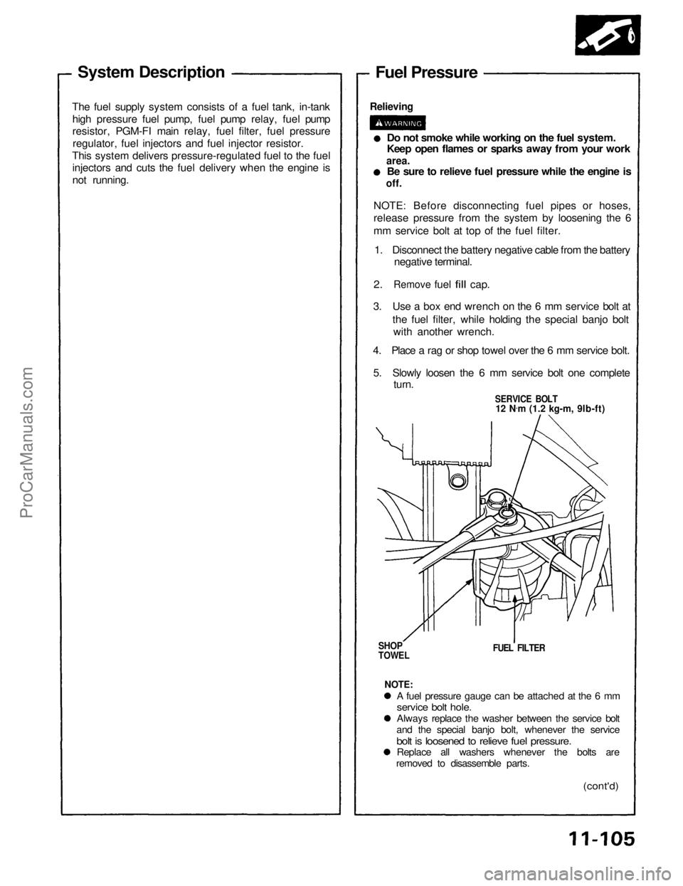
System Description
The fuel supply system consists of a fuel tank, in-tank high pressure fuel pump, fuel pump relay, fuel pump
resistor, PGM-FI main relay, fuel filter, fuel pressureregulator, fuel injectors and fuel injector resistor.
This system delivers pressure-regulated fuel to the fuel injectors and cuts the fuel delivery when the engine is
not running. Fuel Pressure
Relieving
Do not smoke while working on the fuel system.
Keep open flames or sparks away from your work
area.
Be sure to relieve fuel pressure while the engine is
off.
NOTE: Before disconnecting fuel pipes or hoses,
release pressure from the system by loosening the 6
mm service bolt at top of the fuel filter. 1. Disconnect the battery negative cable from the battery negative terminal.
2.
Remove
fuel
fill
cap.
3. Use a box end wrench on the 6 mm service bolt at the fuel filter, while holding the special banjo boltwith another wrench.
4. Place a rag or shop towel over the 6 mm service bolt.
5. Slowly loosen the 6 mm service bolt one complete turn.
SERVICE BOLT
12 N .
m (1.2 kg-m, 9lb-ft)
SHOP
TOWEL
FUEL FILTER
NOTE:
A fuel pressure gauge can be attached at the 6 mm
service bolt hole.
Always replace the washer between the service bolt
and the special banjo bolt, whenever the service
bolt is loosened to relieve fuel pressure.
Replace all washers whenever the bolts are
removed to disassemble parts.
(cont'd)ProCarManuals.com
Page 1110 of 1640

Fuel Supply System
Fuel Pressure (cont'd)
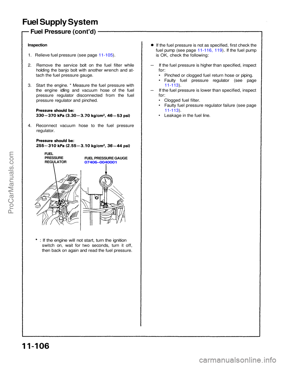
Inspection 1. Relieve fuel pressure (see page 11-105).
2. Remove the service bolt on the fuel filter while holding the banjo bolt with another wrench and at-
tach the fuel pressure gauge.
3. Start the engine. * Measure the fuel pressure with the engine idling and vacuum hose of the fuel
pressure regulator disconnected from the fuel
pressure regulator and pinched.
4. Reconnect vacuum hose to the fuel pressure regulator.
FUEL
PRESSURE
REGULATOR
FUEL PRESSURE GAUGE
07406–0040001
: If the engine will not start, turn the ignition
switch on, wait for two seconds, turn it off,
then back on again and read the fuel pressure. If the fuel pressure is not as specified, first check the
fuel pump (see page 11-116, 119). If the fuel pump
is OK, check the following:
If the fuel pressure is higher than specified, inspect
for:
Pinched or clogged fuel return hose or piping.
Faulty fuel pressure regulator (see page
11-113).
If the fuel pressure is lower than specified, inspect
for:
Clogged fuel filter.Faulty fuel pressure regulator failure (see page
11-113).
Leakage in the fuel line.ProCarManuals.com
Page 1111 of 1640

Fuel Supply System
Fuel Injectors (cont'd)
Replacement
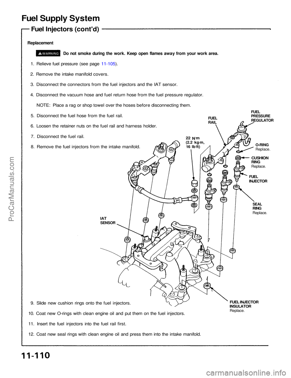
Do not smoke during the work. Keep open flames away from your work area.
1. Relieve fuel pressure (see page 11-105).
2. Remove the intake manifold covers. 3. Disconnect the connectors from the fuel injectors and the IAT sensor.
4. Disconnect the vacuum hose and fuel return hose from the fuel pressure regulator. NOTE: Place a rag or shop towel over the hoses before disconnecting them.
5. Disconnect the fuel hose from the fuel rail.
6. Loosen the retainer nuts on the fuel rail and harness holder.
7. Disconnect the fuel rail.
8. Remove the fuel injectors from the intake manifold.
FUEL
PRESSURE
REGULATOR
22 N.m
(2.2 kg .
m,
16 Ib.ft)
FUEL
RAIL
O-RING
Replace.
CUSHION
RING
Replace.
FUEL
INJECTOR
SEAL
RING
Replace.
FUEL INJECTOR
INSULATOR
Replace.
IAT
SENSOR
9. Slide new cushion rings onto the fuel injectors.
10. Coat new O-rings with clean engine oil and put them on the fuel injectors.
11. Insert the fuel injectors into the fuel rail first.
12. Coat new seal rings with clean engine oil and press them into the intake manifold.ProCarManuals.com
Page 1112 of 1640
13. Install the fuel injectors and fuel rail assembly in the manifold.
CAUTION: To prevent damage to the O-rings. install the fuel injectors in the fuel rail first, then install them in the in-
take manifold.
INTAKE MANIFOLD
COVERS
22 N .
m
(2.2 kg .
m, 16 Ib .
ft)
CONNECTOR
FUEL RAIL
INSULATOR FUEL RAIL
MARKINGS
12 N
.
m
(1.2 kg.m.
9 Ib.ft)
14. Align the center line on the connector with the mark on the fuel rail.
15. Install and tighten the retainer nuts.
16. Connect the fuel hose to the fuel rail.
17. Connect the vacuum hose and fuel return hose to the fuel pressure regulator.
18. Install the connectors on the fuel injectors and the IAT sensor.
19. Install the intake manifold covers.
20. Turn the ignition switch ON, but do not operate the starter. After the fuel pump runs for approximately two seconds,
the fuel pressure in the fuel line rises. Repeat this two or three times, then check whether there is any fuel leakage.ProCarManuals.com
Page 1113 of 1640
Fuel Supply System
Fuel Injector Resistor
Description
The fuel injector resistor lowers the current supplied to
the fuel injectors to prevent damage to the fuel injector
coils. This allows a faster response time of the fuel
injectors.
ECM
PGM-FI
MAIN
RELAY
Testing
1. Disconnect the fuel injector resistor connector.
2. Check for resistance between each of the fuel in-
jector resistor terminals (B, C, D, F, G and H) and
the power terminal (E).
Resistance should be: 5—7
FUEL
INJECTOR
RESISTOR
B
C
D
F
G
H
E
Replace the fuel injector resistor with a new one
if any of the resistances are outside of the
specification.
FUEL
INJECTOR RESISTOR
FUEL
INJECTORSProCarManuals.com