Page 1123 of 1640
(From page 11-124)
C489 CONNECTOR (6P)
Inspect the fuel pump (see page
11-119).
BLK/
RED (+)
Measure the voltage between
BLK/RED (+) (on wire harness
side of fuel pump) and body
ground when the ignition switch
is first turned ON.
Is there battery voltage?(for 2 seconds)
Repair open in BLK/RED wire be-
tween the fuel pump resistor and
the fuel pump.ProCarManuals.com
Page 1124 of 1640

Fuel Supply System
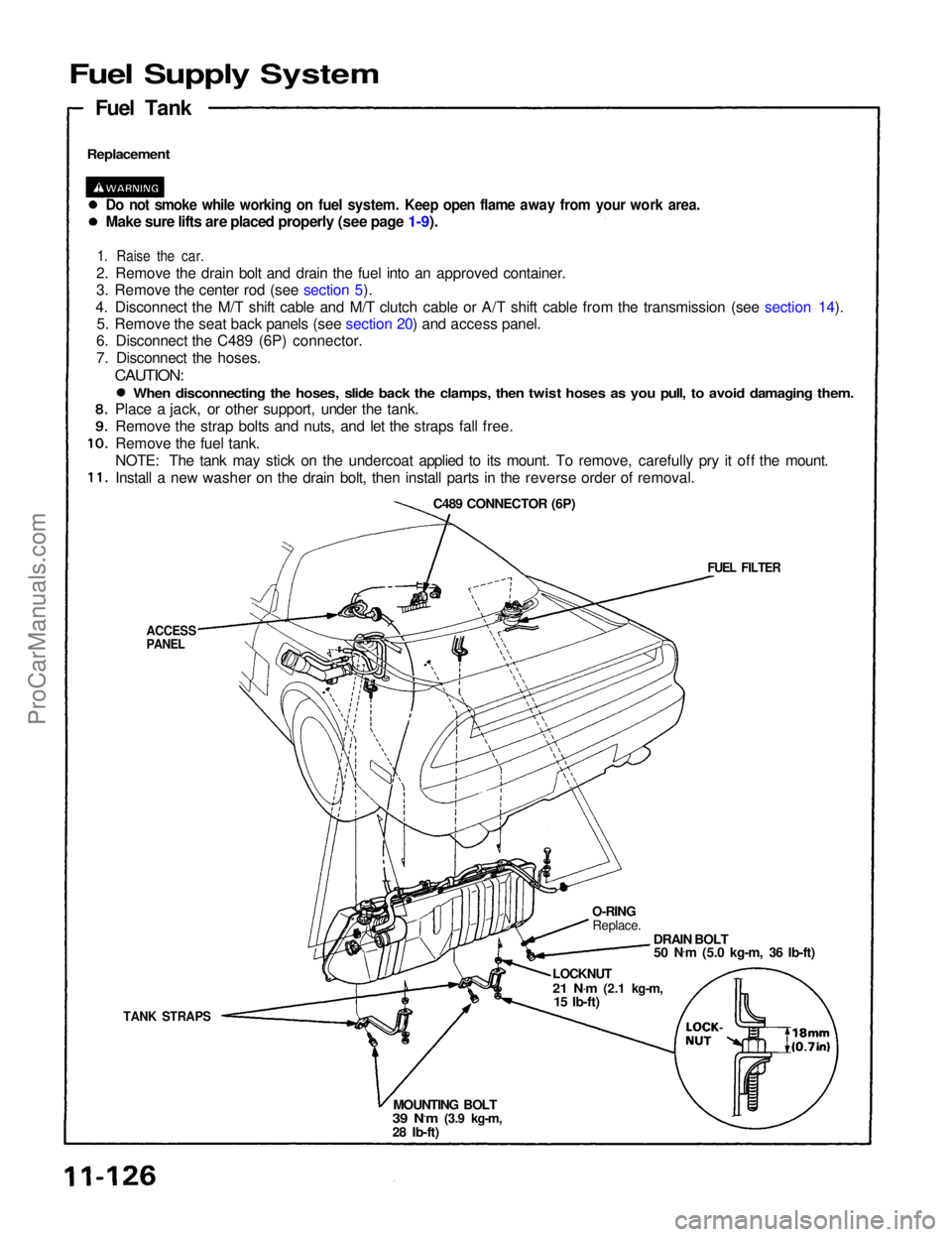
Replacement
Fuel Tank
Do not smoke while working on fuel system. Keep open flame away from your work area.
Make sure lifts are placed properly (see page 1-9).
1. Raise the car.
2. Remove the drain bolt and drain the fuel into an approved container.
3. Remove the center rod (see section 5).
4. Disconnect the M/T shift cable and M/T clutch cable or A/T shift cable from the transmission (see section 14). 5. Remove the seat back panels (see section 20) and access panel.
6. Disconnect the C489 (6P) connector.
7. Disconnect the hoses.
CAUTION:
TANK STRAPS
O-RING
Replace.
DRAIN BOLT50 N .
m (5.0 kg-m, 36 Ib-ft)
LOCKNUT
21 N .
m
(2.1 kg-m,
15 Ib-ft)
MOUNTING BOLT
39 N.m
(3.9 kg-m,
28 Ib-ft)
FUEL FILTER
C489 CONNECTOR (6P)
ACCESS
PANEL
When disconnecting the hoses, slide back the clamps, then twist hoses as you pull, to avoid damaging them.
Place a jack, or other support, under the tank.
Remove the strap bolts and nuts, and let the straps fall free.
Remove the fuel tank.
NOTE: The tank may stick on the undercoat applied to its mount. To remove, carefully pry it off the mount.
Install a new washer on the drain bolt, then install parts in the reverse order of removal.ProCarManuals.com
Page 1142 of 1640

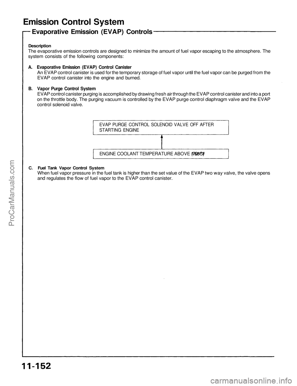
Emission Control System
Description
The evaporative emission controls are designed to minimize the amount of fuel vapor escaping to the atmosphere. The
system consists of the following components:
A. Evaporative Emission (EVAP) Control Canister
An EVAP control canister is used for the temporary storage of fuel vapor until the fuel vapor can be purged from the
EVAP control canister into the engine and burned.
B. Vapor Purge Control System
EVAP control canister purging is accomplished by drawing fresh air through the EVAP control canister and into a port
on the throttle body. The purging vacuum is controlled by the EVAP purge control diaphragm valve and the EVAP
control solenoid valve.
C. Fuel Tank Vapor Control System
When fuel vapor pressure in the fuel tank is higher than the set value of the EVAP two way valve, the valve opens
and regulates the flow of fuel vapor to the EVAP control canister.
EVAP PURGE CONTROL SOLENOID VALVE OFF AFTER
STARTING ENGINE
ENGINE COOLANT TEMPERATURE ABOVE
158°F
(70°C)
Evaporative Emission (EVAP) ControlsProCarManuals.com
Page 1143 of 1640
FUEL
FILL CAP
FUEL TANK
EVAP
CONTROL
CANISTER
FRESH
AIR
EVAP
PURGE CONTROL
DIAPHRAGM
VALVE
(cont'd)
BLK
ECM
TO No. 2
(15 A) FUSE
GRN
EVAP PURGE
CONTROL
SOLENOID VALVE
EVAP
TWO WAY
VALVEProCarManuals.com
Page 1208 of 1640

Troubleshooting Procedures
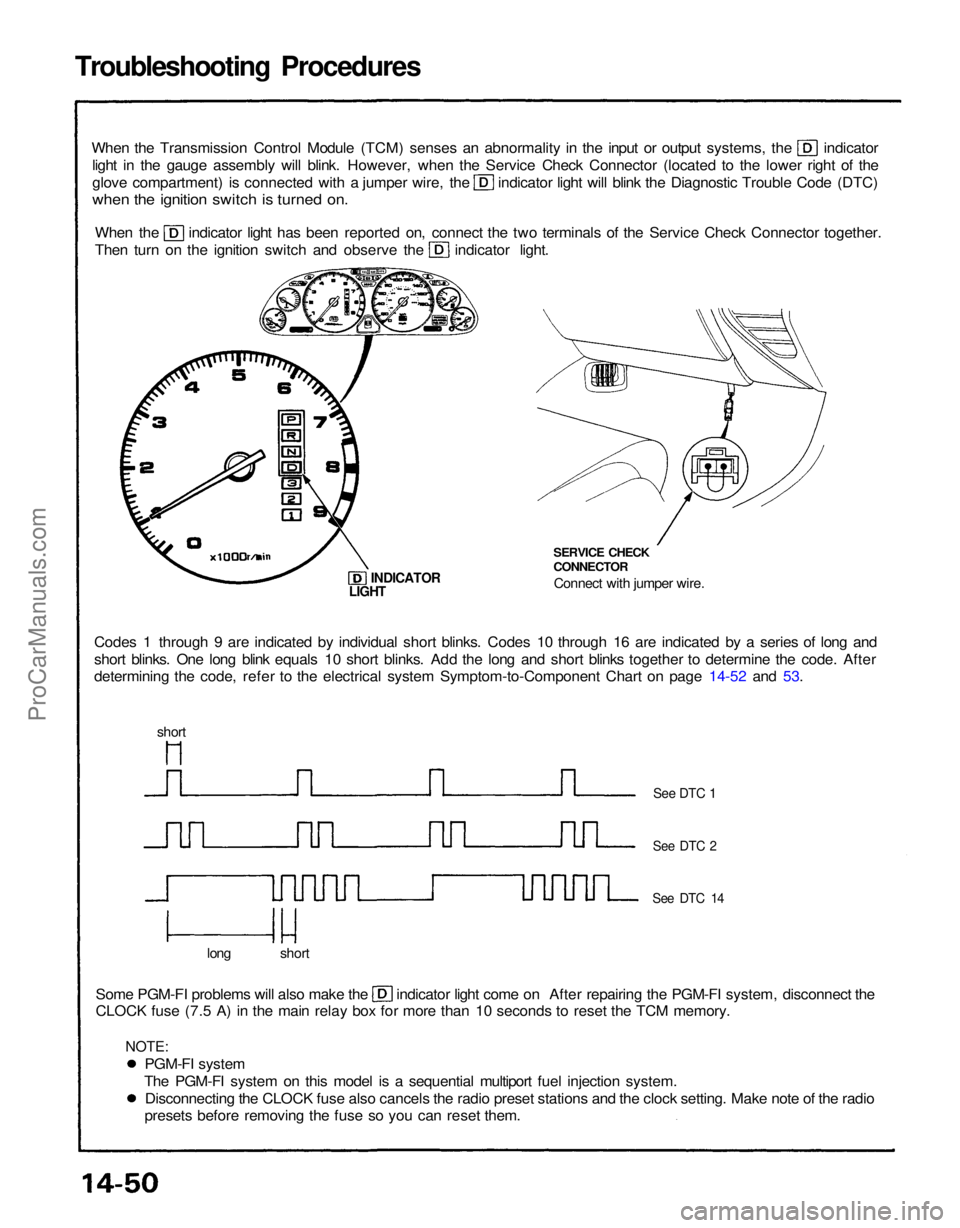
When the Transmission Control Module (TCM) senses an abnormality in the input or output systems, the indicator
light in the gauge assembly will blink. However, when the Service Check Connector (located to the lower right of the glove compartment) is connected with a jumper wire, the indicator light will blink the Diagnostic Trouble Code (DTC)
when the ignition switch is turned on.
When the indicator light has been reported on, connect the two terminals of the Service Check Connector together.
Then turn on the ignition switch and observe the indicator light.
Codes 1 through 9 are indicated by individual short blinks. Codes 10 through 16 are indicated by a series of long and
short blinks. One long blink equals 10 short blinks. Add the long and short blinks together to determine the code. After
determining the code, refer to the electrical system Symptom-to-Component Chart on page 14-52 and 53. SERVICE CHECK
CONNECTOR
Connect with jumper wire.
INDICATOR
Some PGM-FI problems will also make the indicator light come on After repairing the PGM-FI system, disconnect the
CLOCK fuse (7.5 A) in the main relay box for more than 10 seconds to reset the TCM memory.
long short
See DTC 1
See DTC 2
See DTC 14
LIGHT
short
PGM-FI system
The PGM-FI system on this model is a sequential multiport fuel injection system. Disconnecting the CLOCK fuse also cancels the radio preset stations and the clock setting. Make note of the radio
presets before removing the fuse so you can reset them.
NOTE:ProCarManuals.com
Page 1211 of 1640

If a customer describes the symptoms for codes 3, 6, 11, 14 or 1 5 yet the indicator light is not blinking, it will
be necessary to recreate the symptom by test driving, and then checking the indicator light with the ignition
still
ON.
If the indicator light displays codes 1,2,3,8, 11, or 16, check first the No. 9, 13 and 18 and fuse before elec-
trical troubleshooting.
If any of the fuses have blown, repair them and then recheck. If the indicator light displays codes other than those listed above or stays lit continuously, the TCM is faulty.
Sometimes the indicator light and the Malfunction Indicator Lamp (MID/Check Engine light may come on
simultaneously. If so, check the PGM-FI system according to the number of blinks on the MIL/Check Engine light,
then reset the memory by removing the CLOCK fuse in the main relay box for more than 10 seconds. Drive the vehicle for several minutes at speed over 30 mph (50 km/h), then recheck the MIL/Check Engine light.PGM-FI system
The PGM-FI system on this model is a sequential multiport fuel injectin system.
The indicator light may comes on, indicating a system problem, when, in fact, there is a poor or intermittent
electrical connection. First, check the electrical connections, clean or repair connections if necessary.If the electrical readings are not as specified when using the test harness, check the test harness connections
before proceeding.
Disconnecting the CLOCK fuse also cancels the radio preset stations and the clock setting. Make note of the radio
presets before removing the fuse so you can reset them. If the self-diagnosis indicator light does not blink, perform an inspection according to the table listed below.
Symptom
• Lock-up clutch does not
engage.
• Transmission jerks hard when shifting.
• Transmission jerks hard when
shifting.
• Transmission jerks hard when
shifting
• Lock-up clutch does not
engage.
14-7214-70 14-68
14-67
Refer to
page
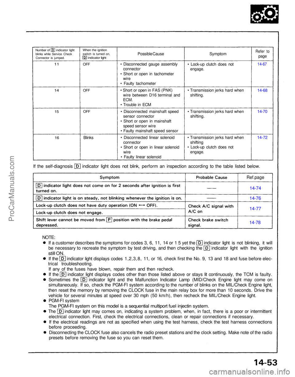
Possible Cause
• Disconnected gauge assembly connector
• Short or open in tachometer wire
• Faulty tachometer
• Short or open in FAS (PNK) wire between D16 terminal and
ECM.
• Trouble in ECM
• Disconnected mainshaft speed sensor connector
• Short or open in mainshaft speed sensor wire
• Faulty mainshaft speed sensor
• Disconnected linear solenoid connector
• Short or open in linear solenoid wire
• Faulty linear solenoid
Blinks
OFF
OFF
OFF
When the ignition
switch is turned on,
indicator light
Number of indicator light
blinks while Service CheckConnector is jumped.
11
14
15
16
Ref.page
14-74
14-76
14-77
14-78
NOTE:ProCarManuals.com
Page 1324 of 1640
System Description
Electrical Power Steering (EPS)
Outline
The NSX uses an electric motor-driven power steering, which possesses the characteristics best suited for a mid engine
automobile. This system is a power-assisted steering device, with a motor inside the steering gearbox driven by the EPS
control unit and power unit. Its distinctive features are described below:
ALTERNATOR
VEHICLE
SPEED SENSOR
STEERING WHEEL
EPS CONTROL UNIT
POWER UNIT
BATTERY
STEERING GEARBOX
STEERING
COLUMN
Minimized loss of engine horsepower and decreased fuel consumption.
A linear steering feel and the reduction of kickback.
The system is compact and lightweight because it requires no complicated hydraulic piping, etc.ProCarManuals.com
Page 1387 of 1640
RETRACTABLE HEADLIGHT
CONTROL UNIT
INTERLOCK CONTROL
UNIT (A/T)
FUEL PUMP RELAY
Wire colors: YEL, RED,
BLK/YEL, and BLK/REDProCarManuals.com