Page 1509 of 1640

Fuel Supply System
Fuel Pump (cont'd)
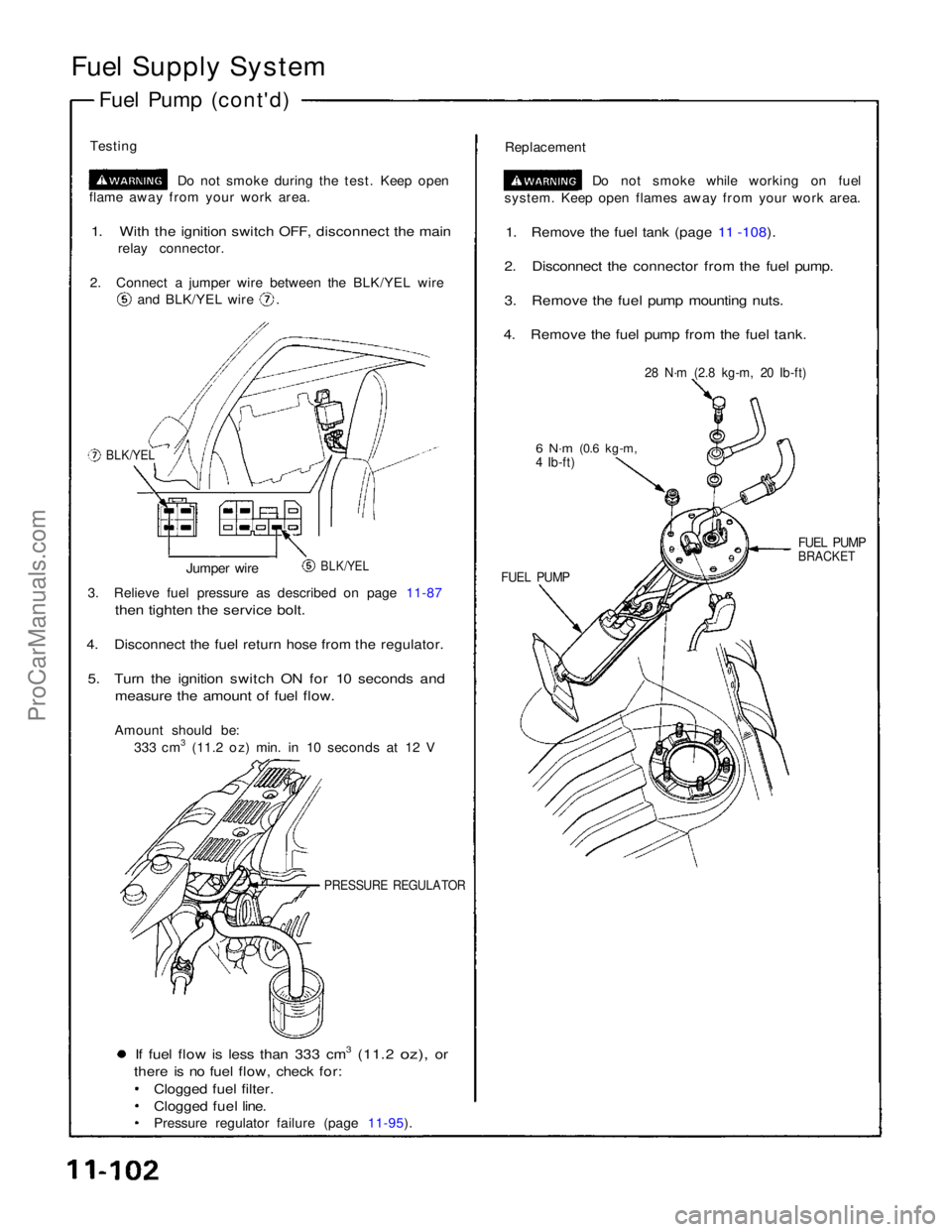
Testing Do not smoke during the test. Keep open
flame away from your work area.
1. With the ignition switch OFF, disconnect the main
relay connector.
2. Connect a jumper wire between the BLK/YEL wire and BLK/YEL wire .
Replacement
Do not smoke while working on fuel
system. Keep open flames away from your work area.
1. Remove the fuel tank (page 11 -108).
2. Disconnect the connector from the fuel pump.
3. Remove the fuel pump mounting nuts.
4. Remove the fuel pump from the fuel tank.
BLK/YEL
28 N·m (2.8 kg-m, 20 Ib-ft)
6 N·m
(0.6 kg-m,
4 Ib-ft)
BLK/YEL
Jumper wire
FUEL PUMP
FUEL PUMP
BRACKET
3. Relieve fuel pressure as described on page 11-87
then tighten the service bolt.
4. Disconnect the fuel return hose from the regulator.
5. Turn the ignition switch ON for 10 seconds and
measure the amount of fuel flow.
Amount should be: 333 cm3 (11.2 oz) min. in 10 seconds at 12 V
PRESSURE REGULATOR
If fuel flow is less than 333 cm3 (11.2 oz), or
there is no fuel flow, check for:
Clogged fuel filter.
Clogged fuel line.
Pressure regulator failure (page 11-95).ProCarManuals.com
Page 1510 of 1640

Main Relay
Description
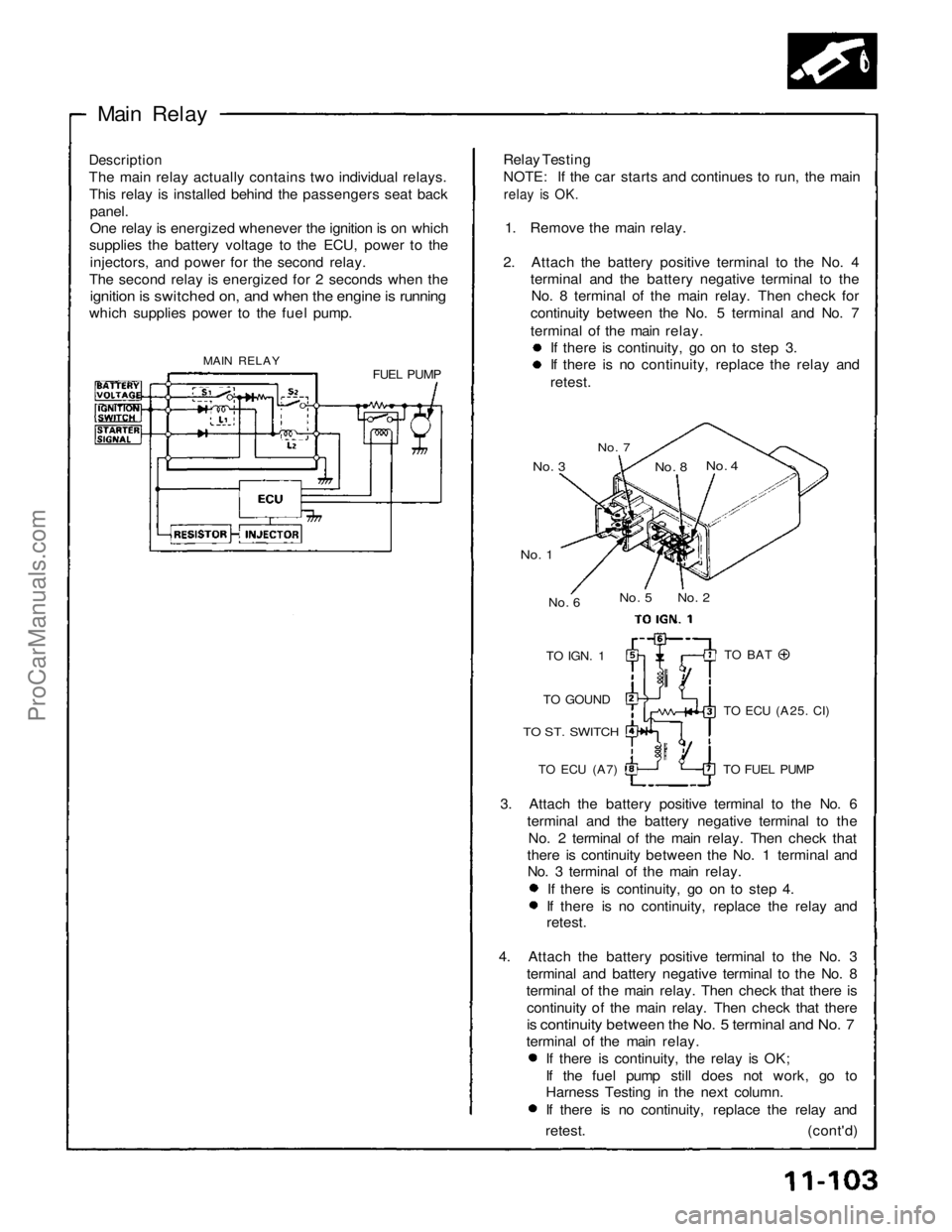
The main relay actually contains two individual relays. This relay is installed behind the passengers seat back
panel.
One relay is energized whenever the ignition is on which
supplies the battery voltage to the ECU, power to the
injectors, and power for the second relay.
The second relay is energized for 2 seconds when the
ignition is switched on, and when the engine is running
which supplies power to the fuel pump.
MAIN RELAY FUEL PUMPRelay Testing
NOTE: If the car starts and continues to run, the main
relay is OK.
1. Remove the main relay.
2. Attach the battery positive terminal to the No. 4 terminal and the battery negative terminal to theNo. 8 terminal of the main relay. Then check for
continuity between the No. 5 terminal and No. 7
terminal of the main relay. If there is continuity, go on to step 3. If there is no continuity, replace the relay and
retest.
No. 7
No. 3
No. 4
No. 8
No. 2
No. 5
No. 6
No. 1
TO
IGN.
1
TO GOUND
TO ST. SWITCH
TO ECU
(A7)
TO BAT
TO ECU
(A25.
CI)
TO FUEL PUMP
3. Attach the battery positive terminal to the No. 6 terminal and the battery negative terminal to theNo. 2 terminal of the main relay. Then check that
there is continuity between the No. 1 terminal and No. 3 terminal of the main relay.
If there is continuity, go on to step 4. If there is no continuity, replace the relay and
retest.
4. Attach the battery positive terminal to the No. 3 terminal and battery negative terminal to the No. 8
terminal of the main relay. Then check that there is
continuity of the main relay. Then check that there
is continuity between the No. 5 terminal and No. 7
terminal of the main relay. If there is continuity, the relay is OK;
If the fuel pump still does not work, go to
Harness Testing in the next column.
If there is no continuity, replace the relay and
retest. (cont'd)ProCarManuals.com
Page 1511 of 1640
Fuel Supply System
Main Relay (cont'd)
Troubleshooting Flowchart
Engine will not start.
Inspection of main relay.
Disconnect the main relay con-
nectors.
Measure the voltage between YEL/BLU terminal and body
ground.
Is there battery voltage? Replace ACG fuse.
Turn the ignition switch ON.
Measure the voltage between BLK/YEL terminal and body
ground.
Replace No. 2 fuse.
Is there battery voltage?
Measure the voltage between BLK/YEL terminal and body
ground.
Is there battery voltage? Replace IG COIL fuse. MAIN RELAY
BLK/
WHT
GRW
BLK
YEL/BLK
BLK/YEL
BLK/YEL
YEL/BLU
BLK
BLK/YEL
Turn the ignition switch START
position with the clutch pedal
depressed.
Measure the voltage between BLK/WHT terminal and body
ground.
Is there battery voltage? Replace No. 7 fuse.
(To page 11-105)ProCarManuals.com
Page 1513 of 1640
Fuel Supply System
Fuel Pump Resistor
Troubleshooting Flowchart
Engine will not start.
Inspection of fuel pump
resistor.
Disconnect the fuel pump resis-
tor connector.
Measure the voltage between
BLK/YEL (+) (on harness side)
and body ground (-) when the ig-
nition switch is first turned ON.
Is there battery voltage?
(for 2 seconds)
Inspect the main relay (page
11-104)
Turn the ignition switch OFF.
FUEL PUMP
RESISTOR
JUMPER WIRE
Replace fuel pump resistor.
Install a jumper wire between
two terminals on the wire harness side of fuel pump
resistor.
Turn the ignition switch to
START position.
Does the engine start?
Turn the ignition switch OFF.
Disconnect the fuel pump con-
nector.
(To page 11-107)ProCarManuals.com
Page 1514 of 1640
(From page 11-106)
Measure the voltage between
BLK/RED (+) (on wire harness
side of fuel pump) and body
ground when the ignition switch
is first turned ON.
Is there battery voltage?
(for 2 seconds)
Repair open in BLK/RED wire be-
tween the fuel pump resistor and
the fuel pump. Inspect the fuel pump
(page 11-102)
BLK/
REDProCarManuals.com
Page 1515 of 1640

Fuel Supply System
Fuel Tank
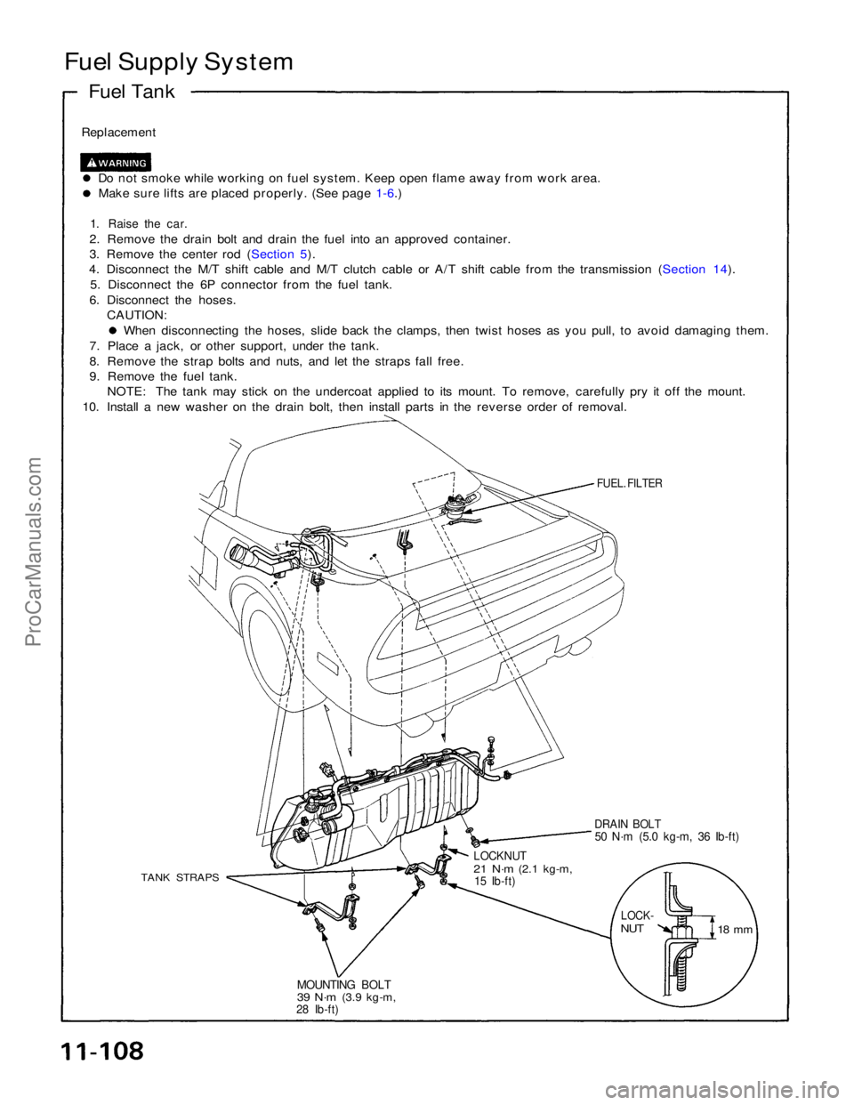
Replacement
Do not smoke while working on fuel system. Keep open flame away from work area.Make sure lifts are placed properly. (See page 1-6.)
1. Raise the car.
2. Remove the drain bolt and drain the fuel into an approved container.
3. Remove the center rod (Section 5).
4. Disconnect the M/T shift cable and M/T clutch cable or A/T shift cable from the transmission (Section 14).
5. Disconnect the 6P connector from the fuel tank.
6. Disconnect the hoses. CAUTION: When disconnecting the hoses, slide back the clamps, then twist hoses as you pull, to avoid damaging them.
7. Place a jack, or other support, under the tank.
8. Remove the strap bolts and nuts, and let the straps fall free.
9. Remove the fuel tank. NOTE: The tank may stick on the undercoat applied to its mount. To remove, carefully pry it off the mount.
10. Install a new washer on the drain bolt, then install parts in the reverse order of removal.
FUEL. FILTER
DRAIN BOLT
50 N·m (5.0 kg-m, 36 Ib-ft)
LOCKNUT
21 N·m
(2.1 kg-m,
15 Ib-ft)
TANK STRAPS
LOCK-
NUT
18 mm
MOUNTING BOLT
39 N·m
(3.9 kg-m,
28 Ib-ft)ProCarManuals.com
Page 1532 of 1640
Evaporative Emission Controls
Description
The evaporative controls are designed to minimize the amount of fuel vapor escaping to the atmosphere. The system consists of
the following components:
A. Charcoal Canister
A canister for the temporary storage of fuel vapor until the fuel vapor can be purged from the canister into the engine and
burned.
B. Vapor Purge Control System
Canister purging is accomplished by drawing fresh air through the canister and into a port on the throttle body. The
purging vacuum is controlled by the purge control diaphragm valve and the purge cut-off solenoid valve.
C. Fuel Tank Vapor Control System
When fuel vapor pressure in the fuel tank is higher than the set value of the two-way valve, the valve opens and regulates
the flow of fuel vapor to the canister.
(cont'd)
PURGE CUT-OFF SOLENOID VALVE OFF AFTER START-
ING ENGINE
COOLANT TEMPERATURE ABOVE 70°C (1 58°F)ProCarManuals.com
Page 1533 of 1640
Emission Control System
Evaporative Emission Controls (cont'd)
FUEL
FILLER CAP
FUEL TANK
PURGE CUT-OFF
SOLENOID VALVE
ECU
TO No. 2
FUSE
BLK/YEL
GRN
TWO-WAY
VALVE
CANISTER
FRESH
AIR
PURGE CONTROL
DIAPHRAGM
VALVEProCarManuals.com