Page 1107 of 1640
6. Turn the ignition switch OFF.
7. Reconnect the 2P connector on the IAC valve, then
remove CLOCK fuse in the under-hood fuse/relay
box for 10 seconds to reset ECM.
8. Restart and idle the engine with no-load conditions
in which the headlights, blower fan, rear defogger,
cooling fan, and air conditioner are not operating
for one minute, then check the idle speed.
Idle speed should be:
M/T
A/T
800
50 rpm
750
50 rpm
(in or range)ProCarManuals.com
Page 1127 of 1640
Air Cleaner (ACL)
ACL Element Replacement
ACL HOUSING
COVER
ACL ELEMENT
Replace ACL element every
30,000 miles (48,000 km) or 24 months.
Clean ACL element every 7,500 miles
(12,000 km) or 6 months under dusty
conditions, rough or muddy roods.
INTAKE
AIR DUCT
RESONATOR
ACL HOUSINGProCarManuals.com
Page 1178 of 1640
Description
Electronic Control System (cont'd)
TRANSMISSION CONTROL MODULE (TCM)
ENGINE
CONTROL
MODULE
(ECM) Shift Control
Lock-up
Control
TCS Control Unit
EPS Control Unit Engine RPM
Air Conditioning Signal Brake Switch Signal
Vehicle Speed Sensor Signal
Mainshaft Speed Sensor Signal
Countershaft Speed Sensor Signal
Self-Diagnosis
Function
Self-Diagnosis Indicator
INTERLOCK
CONTROL UNIT
Lock-up Control Solenoid
Valve B
Lock-up Control Solenoid
Valve A Shift Control Solenoid
Valve B
Shift Control Solenoid
Valve A
Linear Solenoid
Throttle Position
Sensor Signal
Engine Coolant
Temperature
Sensor Signal
Accet Pedal
Angle Signal
Service Check
Connector
ProCarManuals.com
Page 1252 of 1640
SPRING SPECIFICATIONS
Unit of length: mm (in)
After disassembly of the ATF strainer, check that it is in good condition, and the inlet opening is not clogged.
Replace the strainer with a new one if it is clogged or damaged.
The strainer can be reused if it is not clogged. Clean the inlet opening thoroughly with compressed air before reinstall-
ing it.
ATF STRAINER
INLET OPENING
NOTE:ProCarManuals.com
Page 1365 of 1640

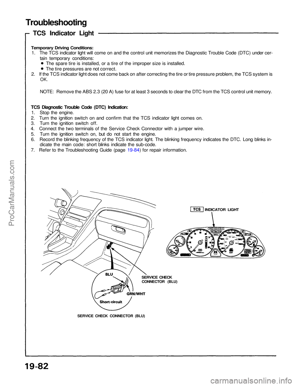
Troubleshooting
TCS Indicator Light
Temporary Driving Conditions:
1. The TCS indicator light will come on and the control unit memorizes the Diagnostic Trouble Code (DTC) under cer-
tain temporary conditions:
2. If the TCS indicator light does not come back on after correcting the tire or tire pressure problem, the TCS system is
OK.
NOTE: Remove the ABS 2.3 (20 A) fuse for at least 3 seconds to clear the DTC from the TCS control unit memory.
TCS Diagnostic Trouble Code (DTC) Indication: 1. Stop the engine.
2. Turn the ignition switch on and confirm that the TCS indicator light comes on.
3. Turn the ignition switch off.
4. Connect the two terminals of the Service Check Connector with a jumper wire.
5. Turn the ignition switch on, but do not start the engine.6. Record the blinking frequency of the TCS indicator light. The blinking frequency indicates the DTC. Long blinks in- dicate the main code: short blinks indicate the sub-code.
7. Refer to the Troubleshooting Guide (page 19-84) for repair information. The spare tire is installed, or a tire of the improper size is installed.
The tire pressures are not correct.
SERVICE CHECK CONNECTOR (BLU)
SERVICE CHECK
CONNECTOR (BLU)
INDICATOR LIGHTProCarManuals.com
Page 1418 of 1640

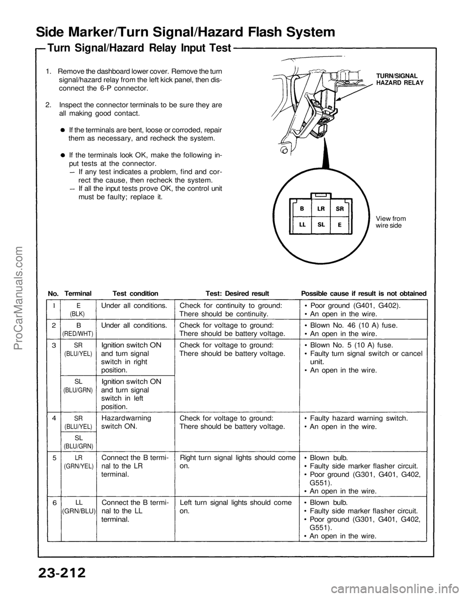
Side Marker/Turn Signal/Hazard Flash System
Turn Signal/Hazard Relay Input Test
1. Remove the dashboard lower cover. Remove the turn signal/hazard relay from the left kick panel, then dis-
connect the 6-P connector.
2. Inspect the connector terminals to be sure they are all making good contact.
If the terminals are bent, loose or corroded, repair
them as necessary, and recheck the system.
If the terminals look OK, make the following in-
put tests at the connector. If any test indicates a problem, find and cor-
rect the cause, then recheck the system. If all the input tests prove OK, the control unit
must be faulty; replace it.
View from
wire side
TURN/SIGNAL
HAZARD RELAY
1
2
3
4
5
6
B
(RED/WHT)
SR
(BLU/YEL)
SL
(BLU/GRN)
SR
(BLU/YEL)
SL
(BLU/GRN)
LR
(GRN/YEL)
LL
(GRN/BLU)
Test condition
Under all conditions.
Ignition switch ON
and turn signal
switch in right position.
Ignition switch ON
and turn signal switch in left
position.
Connect the B termi-
nal to the LR
terminal.
Connect the B termi-
nal to the LL
terminal.
Test: Desired result
Check for continuity to ground:
There should be continuity.
Check for voltage to ground:
There should be battery voltage.
Check for voltage to ground:
There should be battery voltage.
Check for voltage to ground:
There should be battery voltage.
Right turn signal lights should come
on.
Left turn signal lights should come
on.
Possible cause if result is not obtained
Poor ground (G401, G402).
An open in the wire.
Blown No. 46 (10 A) fuse.
An open in the wire.
Blown No. 5 (10 A) fuse.
Faulty turn signal switch or cancel
unit.
An open in the wire.
Faulty hazard warning switch.
An open in the wire.
Blown bulb.
Faulty side marker flasher circuit.
Poor ground (G301, G401, G402,
G551).
An open in the wire.
Blown bulb.
Faulty side marker flasher circuit.
Poor ground (G301, G401, G402,
G551).
An open in the wire.
E
(BLK)
Terminal
No.
Under all conditions.
Hazard warning
switch ON.ProCarManuals.com
Page 1419 of 1640

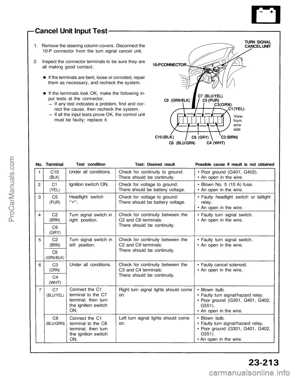
Cancel Unit Input Test
1. Remove the steering column covers. Disconnect the 10-P connector from the turn signal cancel unit.
2. Inspect the connector terminals to be sure they are all making good contact.
If the terminals are bent, loose or corroded, repair
them as necessary, and recheck the system.
If the terminals look OK, make the following in-
put tests at the connector. If any test indicates a problem, find and cor-
rect the cause, then recheck the system. If all the input tests prove OK, the control unit
must be faulty; replace it.
C9 (GRN/BLK)
C10
(BLK)
10-P CONNECTOR
TURN SIGNAL
CANCEL UNIT
C7 (BLU/YEL)
C5
(PUR)
C3(ORN)
C1
(YEL)
View
from
wire
side
C2
(BRN)
C4
(WHT)
C6
(GRY)
C8 (BLU/GRN)
Test condition
Under all conditions.
Ignition switch ON.
Headlight switch
Turn signal switch in right position.
Turn signal switch in
left position.
Under all conditions.
Connect the C1
terminal to the C7
terminal, then turn
the ignition switch
ON.
Connect the C1
terminal to the C8
terminal, then turn
the ignition switch
ON.
Test: Desired result
Check for continuity to ground:
There should be continuity.
Check for voltage to ground:
There should be battery voltage.
Check for voltage to ground:
There should be battery voltage.
Check for continuity between the
C2 and C6 terminals:
There should be continuity.
Check for continuity between the
C2 and C9 terminals:
There should be continuity.
Check for continuity between the
C3 and C4 terminals:
There should be continuity.
Right turn signal lights should come
on.
Left turn signal lights should come
on.
Possible cause if result is not obtained
Poor ground (G401, G402).
An open in the wire.
Blown No. 5 (10 A) fuse.
An open in the wire.
Faulty headlight switch or taillight
relay.
An open in the wire.
Faulty turn signal switch.
An open in the wire.
Faulty turn signal switch.
An open in the wire.
Faulty cancel solenoid.
An open in the wire.
Blown bulb.
Faulty turn signal/hazard relay.
Poor ground (G301, G401, G402,
G551).
An open in the wire.
Blown bulb.
Faulty turn signal/hazard relay.
Poor ground (G301, G401, G402,
G551).
An open in the wire.
No.
Terminal
C10
(BLK)
1
2
C1
(YEL)
C5
(PUR)
3
4
C2
(BRN)
C6
(GRY)
5
C2
(BRN)
C9
(GRN/BLK)
6
C3
(ORN)
C4
(WHT)
7
C7
(BLU/YEL)
C8
(BLU/GRN)ProCarManuals.com
Page 1456 of 1640
Label Locations
SRS CAUTION LABELS: Refer to page 1-6.
BATTERY CAUTION ALB CAUTION
ALB and BRAKE
FLUID CAUTION
COOLING FAN
CAUTION
RADIATOR BLEED
PLUG CAUTION
AIR CONDITIONER
CAUTION
RETRACTABLE
HEADLIGHT CAUTION
FAN CAUTION
EXPANSION
TANK CAP
CAUTION
COOLANT
CAUTION PRECAUTION
EMISSION CONTROL
INFORMATION and
VACUUM HOSE
ROUTING DIAGRAM
SPARK PLUG
CAUTION
TIRE INFORMATIONProCarManuals.com