Page 726 of 1640

A/C Syste m Servic e
Leak Tes t
Only us e servic e equipmen t tha t i s U.L.-liste d an d is cer -
tified to mee t th e requirement s o f SA E J221 0 to remov e
HFC-134 a (R-134a ) fro m th e ai r conditionin g system .
CAUTION : Exposur e t o ai r conditione r refrigeran t
an d lubrican t vapo r o r mis t ca n irritat e eyes , nos e
an d throat . Avoi d breathin g th e ai r conditione r
refrigeran t an d lubrican t vapo r o r mist .
I f accidenta l syste m discharg e occurs , ventilat e wor k
are a befor e resumin g service .
R-134 a servic e equipmen t o r vehicl e ai r conditionin g sys -
te m shoul d no t b e pressur e teste d o r lea k teste d wit h
compresse d air .
Som e mixture s o f ai r an d R-134 a hav e
bee n show n to b e combustibl e a t elevate d pressure s
an d ca n resul t i n fir e o r explosio n causin g injur y o r
propert y damage . Neve r us e compresse d ai r t o pres -
sur e tes t R-134 a servic e equipmen t o r vehicl e ai r
conditione r systems.
Additiona l healt h an d safet y informatio n ma y b e obtaine d
fro m th e refrigeran t an d lubrican t manufacturers .
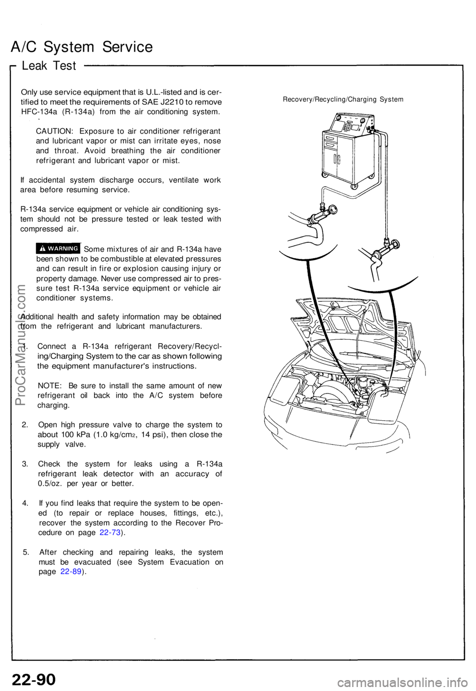
1 . Connec t a R-134 a refrigeran t Recovery/Recycl -
ing/Charging Syste m to th e ca r a s show n followin g
the equipmen t manufacturer' s instructions .
NOTE: B e sur e t o instal l th e sam e amoun t o f ne w
refrigeran t oi l bac k int o th e A/ C syste m befor e
charging .
2 . Ope n hig h pressur e valv e t o charg e th e syste m to
abou t 10 0 kP a (1. 0 kg/cm2, 1 4 psi) , the n clos e th e
suppl y valve .
3 . Chec k th e syste m fo r leak s usin g a R-134 a
refrigeran t lea k detecto r wit h a n accurac y o f
0.5/oz . pe r yea r o r better .
4 . I f yo u fin d leak s tha t requir e th e syste m to b e open -
e d (t o repai r o r replac e houses , fittings , etc.) ,
recove r th e syste m accordin g t o th e Recove r Pro -
cedur e o n pag e 22-73 ).
5 . Afte r checkin g an d repairin g leaks , th e syste m
mus t b e evacuate d (se e Syste m Evacuatio n o n
pag e 22-89 ).
Recovery/Recycling/Chargin g Syste m
ProCarManuals.com
Page 802 of 1640

Interlock System
Control Unit Input Test
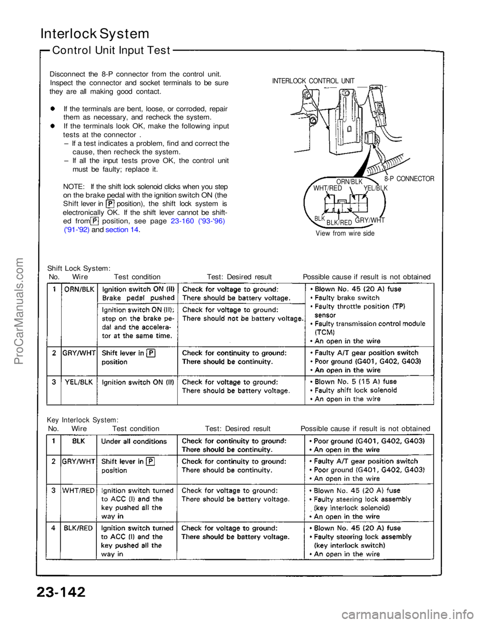
Disconnect the 8-P connector from the control unit. Inspect the connector and socket terminals to be sure
they are all making good contact.
If the terminals are bent, loose, or corroded, repair
them as necessary, and recheck the system.
I
f
the terminals look OK, make the following input
tests at the connector .
– If a test indicates a problem, find and correct the cause, then recheck the system.
– If all the input tests prove OK, the control unit must be faulty; replace it.
NOTE: If the shift lock solenoid clicks when you step
on the brake pedal with the ignition switch ON (the
Shift lever in position), the shift lock system is
electronically OK. If the shift lever cannot be shift-
ed from position, see page 23-160 ('93-'96)
('91-'92) and section 14
.
Shift Lock System:
No. Wire Test condition Test: Desired result Possible cause if result is not obtained
Key Interlock System:
No. Wire Test condition Test: Desired result Possible cause if result is not obtained
8-P CONNECTOR
View from wire side
INTERLOCK CONTROL UNIT
ORN/BLK
WHT/RED
YEL/BLK
BLK
BLK/RED
GRY/WHTProCarManuals.com
Page 830 of 1640
Lighting System
Daytime Running Lights Control Unit Input Test (Canada)
Remove the glove box lower panel and glove box.
Disconnect the 4-P and 8-P connectors from the daytime
running lights control unit.
Inspect the connector and socket terminals to be sure
they are all making good contact.
• If the terminals are bent, loose, or corroded, repair
them as necessary, and recheck the system.
• If the terminals look OK, make the following input
tests at the connector.
— If any test indicates a problem, find and correct
the cause, then recheck the system.
— If all the input tests prove OK, the control unit
must be faulty; replace it.
DAYTIME RUNNING LIGHTS
CONTROL UNIT (Canada)
4-P CONNECTOR
View from wire side
No. Wire
Test condition
Test: Desired result
Possible cause if result is not obtained
8-P CONNECTORProCarManuals.com
Page 865 of 1640
Side Marker/Turn Signal/Hazard Flasher System
Turn Signal/Hazard Relay Input Test
1. Remove the dashboard lower cover. Remove the
turn signal/hazard relay from the left kick panel,
then disconnect the 6-P connector.
2. Inspect the connector and socket terminals to be
sure they are all making good contact.
• If the terminals are bent, loose or corroded, repair
them as necessary, and recheck the system.
• If the terminals look OK, make the following input
tests at the connector.
— If any test indicates a problem, find and cor-
rect the cause, then recheck the system.
— If all the input tests prove OK, the control unit
must be faulty; replace it.
TURN/SIGNAL
HAZARD RELAY
View from
wire side
No. Terminal
Test condition
Test: Desired result
Possible cause if result is not obtainedProCarManuals.com
Page 866 of 1640
Cancel Unit Input Test
1. Remove the steering column covers. Disconnect the
10-P connector from the turn signal cancel unit.
2. Inspect the connector terminals to be sure they are
all making good contact.
• If the terminals are bent, loose or corroded, repair
them as necessary, and recheck the system.
• If the terminals look OK, make the following input
tests at the connector.
— If any test indicates a problem, find and correct
the cause, then recheck the system.
— If all the input tests prove OK, the control unit
must be faulty; replace it.
10-P CONNECTOR
TURN SIGNAL
CANCEL UNIT
No. Terminal
Test condition
Test: Desired result
Possible cause if result is not obtainedProCarManuals.com
Page 871 of 1640
Dash Lights Brightness Control
Control Unit Input Test
1. Disconnect the 7-P connector from the control unit.
2. Inspect the connector and socket terminals to be sure
they are all making good contact.
• If the terminals are bent, loose or corroded, repair
them as necessary, and recheck the system.
• If the terminals look OK, make the following input
tests at the connector.
— If any test indicates a problem, find and correct
the cause, then recheck the system.
— If all the input tests prove OK, the control unit
must be faulty; replace it.
RED/GRN
BLK
DASH LIGHTS
BRIGHTNESS
CONTROL UNIT
7-P CONNECTOR
View from wire side
RED/BLK
No. Terminal
Test condition
RED/WHT
Test: Desired result
RED
Possible cause if result is not obtainedProCarManuals.com
Page 910 of 1640
Power Windows
Control Unit Input Test
NOTE: The control unit only controls the driver's door
window.
Remove the driver's door panel and disconnect the 4-P
and 6-P connectors from the control unit.
Inspect the connector and socket terminals to be sure
they are all making good contact.
• If the terminals are bent, loose, or corroded, repair
them as necessary, and recheck the system.
• If the terminals look OK, make the following input
tests at the connector.
— If any test indicates a problem, find and correct
the cause, then recheck the system.
— If all the input tests prove OK, the control unit
must be faulty; replace it.
POWER WINDOW
MASTER SWITCH
POWER WINDOW
CONTROL UNIT
No. Wire
Test condition
Test: Desired result
View from wire side
*Not used
Possible cause if result is not obtainedProCarManuals.com
Page 951 of 1640
Security Alarm System
Control Unit Input Test
Remove the glove box, and disconnect the 22-P connec-
tor and 16-P connector from the control unit.
Inspect the connector and socket terminals to be sure
they are all making good contact.
• If the terminals are bent, loose, or corroded, repair
them as necessary, and recheck the system.
• If the terminals look OK, make the following input
tests at the connector.
— If any test indicates a problem, find and correct the
cause, then recheck the system.
— If all the input tests prove OK, the control unit
must be faulty; replace it.
• Different wires with the same color have been given a
number suffix to distinguish them (for example,
YEL/GRN1 and YEL/GRN2 are not the same).
SECURITY
CONTROL UNIT
View from
wire side
Not used
No. Wire
Test condition
Test: Desired result
Possible cause if result is not obtained
22-P
CONNECTOR
16-P CONNECTORProCarManuals.com