Page 1289 of 1640
Transmission
Installation (cont'd)
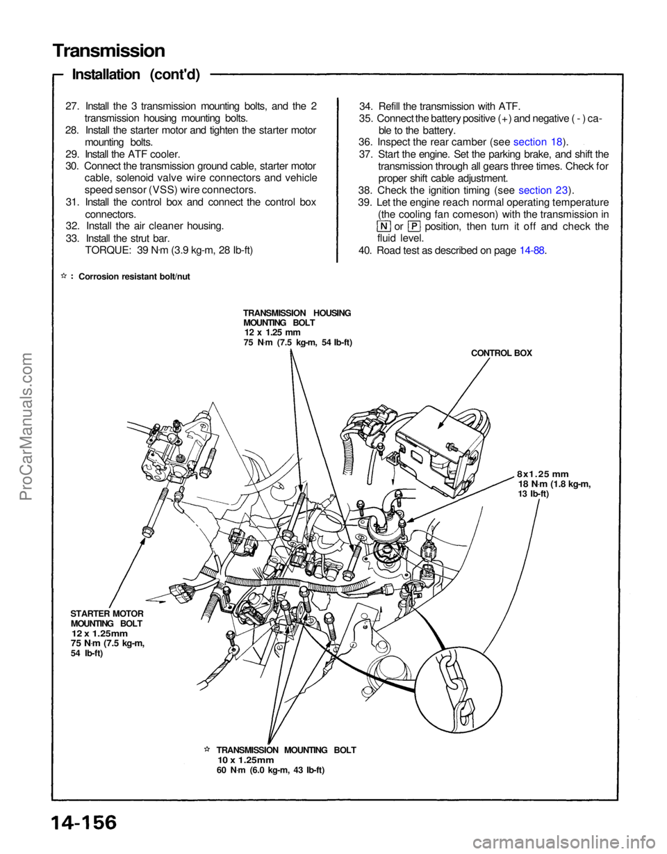
27. Install the 3 transmission mounting bolts, and the 2 transmission housing mounting bolts.
28. Install the starter motor and tighten the starter motor mounting bolts.
29. Install the ATF cooler.
30. Connect the transmission ground cable, starter motor cable, solenoid valve wire connectors and vehicle
speed sensor (VSS) wire connectors.
31. Install the control box and connect the control box connectors.
32. Install the air cleaner housing.
33. Install the strut bar.
TORQUE: 39 N .
m (3.9 kg-m, 28 Ib-ft)
Corrosion resistant bolt/nut 34. Refill the transmission with ATF.
35. Connect the battery positive (+) and negative (-) ca- ble to the battery.
36. Inspect the rear camber (see section 18).
37. Start the engine. Set the parking brake, and shift the transmission through all gears three times. Check forproper shift cable adjustment.
38. Check the ignition timing (see section 23).
39. Let the engine reach normal operating temperature (the cooling fan comeson) with the transmission in or position, then turn it off and check the
fluid level.
40. Road test as described on page 14-88.
TRANSMISSION HOUSING MOUNTING BOLT
12 x
1.25
mm
75 N .
m (7.5 kg-m, 54 Ib-ft)
CONTROL BOX
8x1.25 mm
18 N .
m
(1.8 kg-m,
13 Ib-ft)
TRANSMISSION MOUNTING BOLT
10 x 1.25mm
60 N .
m (6.0 kg-m, 43 Ib-ft)
STARTER MOTOR
MOUNTING BOLT
12 x 1.25mm
75 N .
m
(7.5 kg-m,
54 Ib-ft)ProCarManuals.com
Page 1352 of 1640
Front Suspension
Hub Replacement
1. Loosen the wheel nuts slightly.
2. Raise the front of car and support on safety stands in proper locations (see section 1).
3. Remove the wheel nuts and wheel. NOTE: Before installing the wheel, clean the
mating surfaces of the brake disc and inside of the
wheel.
CENTER
CAP
WHEEL NUT
110 N .
m
(11 kg-m, 80 lb-ft)
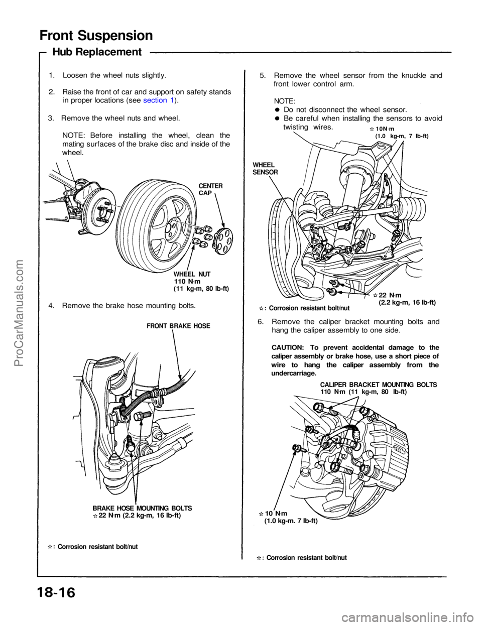
4. Remove the brake hose mounting bolts.
FRONT BRAKE HOSE
BRAKE HOSE MOUNTING BOLTS
Corrosion resistant bolt/nut
5. Remove the wheel sensor from the knuckle and
front lower control arm.
Do not disconnect the wheel sensor.
Be careful when installing the sensors to avoid
twisting wires. 10N.
m
(1.0 kg-m, 7 lb-ft)
WHEEL
SENSOR
22 N.
m
(2.2 kg-m, 16 Ib-ft)
Corrosion resistant bolt/nut
6. Remove the caliper bracket mounting bolts and hang the caliper assembly to one side.
CAUTION: To prevent accidental damage to the
caliper assembly or brake hose, use a short piece of
wire to hang the caliper assembly from the
undercarriage.
CALIPER BRACKET MOUNTING BOLTS
110 N .
m (11 kg-m, 80 Ib-ft)
10 N .
m
(1.0 kg-m. 7 Ib-ft)
Corrosion resistant bolt/nut
22 N
.
m (2.2 kg-m, 16 Ib-ft)
NOTE:ProCarManuals.com
Page 1357 of 1640
Rear Suspension
Hub Replacement
1. Remove the center cap, then pry the spindle nut
lock tab away from the spindle and loosen the nut.
2. Raise the car and support it with safety stands (see section 1).
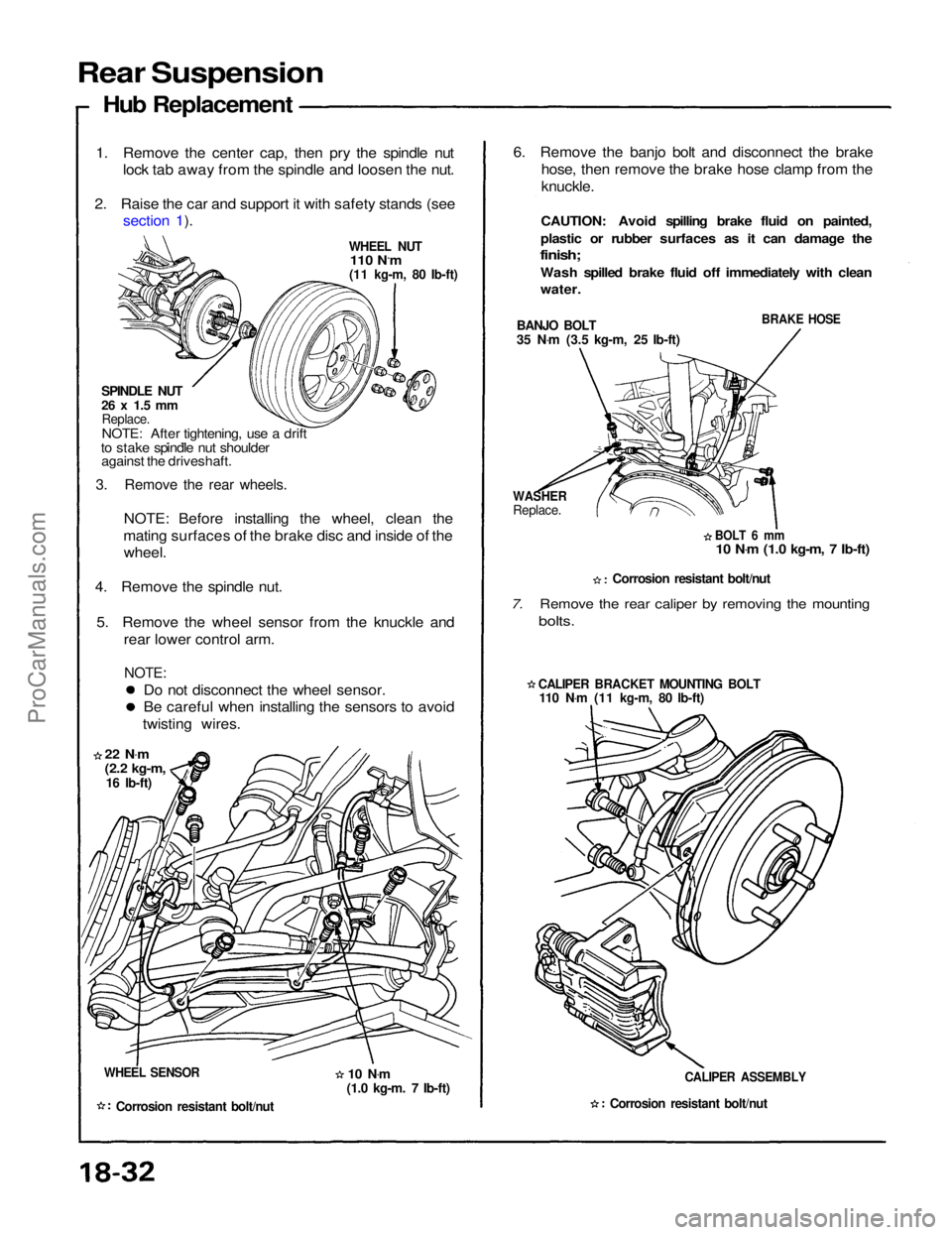
WHEEL NUT
110 N.m
(11 kg-m, 80 Ib-ft)
SPINDLE NUT
26 x 1.5 mm
Replace.
NOTE: After tightening, use a drift
to stake spindle nut shoulder against the driveshaft.
3. Remove the rear wheels.
NOTE: Before installing the wheel, clean the
mating surfaces of the brake disc and inside of the wheel.
4. Remove the spindle nut.
5. Remove the wheel sensor from the knuckle and rear lower control arm.
NOTE:
Do not disconnect the wheel sensor.
Be careful when installing the sensors to avoid
twisting wires.
22 N .
m
(2.2 kg-m,
16 Ib-ft)
WHEEL SENSOR
Corrosion resistant bolt/nut
6. Remove the banjo bolt and disconnect the brake
hose, then remove the brake hose clamp from the
knuckle.
CAUTION: Avoid spilling brake fluid on painted,
plastic or rubber surfaces as it can damage the
finish;
Wash spilled brake fluid off immediately with clean
water.
BANJO BOLT
35 N .
m (3.5 kg-m, 25 Ib-ft)
BRAKE HOSE
WASHER
Replace.
BOLT 6 mm
10 N .
m (1.0 kg-m, 7 Ib-ft)
Corrosion resistant bolt/nut
7. Remove the rear caliper by removing the mounting
bolts.
CALIPER BRACKET MOUNTING BOLT
110 N .
m (11 kg-m, 80 Ib-ft)
CALIPER ASSEMBLY
Corrosion resistant bolt/nut
10 N
.
m
(1.0 kg-m. 7 Ib-ft)ProCarManuals.com
Page 1376 of 1640
Dashboard
Component Removal/Installation (cont'd)
SRS wire harnesses are routed near the dashboard. CAUTION:
LEFT DASH
SENSOR PASSENGER'S
AIRBAG
RIGHT DASH
SENSOR
SRS MAIN
HARNESS
SRS UNIT
Center console panel removal:
NOTE:
Disassemble in numbered sequence.
ASHTRAY
CENTER CONSOLE PANEL
Disconnect the
connectors.
SRS
UNIT
Lift up the parking
brake lever.
Installation is the reverse of the removal procedure. NOTE: Make sure the connectors are connected properly.All SRS wiring harnesses are covered with
yellow outer insulation.
Before disconnecting any part of the SRS wire
harness, install the short connectors (see page
23-328).
Replace the entire affected SRS harness assem-
bly if it has an open circuit or damaged wiring.
Take care not to scratch the dashboard, center console panel and related parts.Do not drop the screws inside the dashboard.
Remove the center armrest (see page 20-49), clock and center air vent (see page 20-50).ProCarManuals.com
Page 1404 of 1640
Blown No. 5 (10 A) fuse
(In the under-dash fuse box)
Blown No. 34 (15 A) fuse
(In the under-dash fuse box)
Safety indicator input
Safety indicator (Diodes)Brake light failure sensorDoor switch
Trunk latch switch
Retractable headlight control unit
(see page 23-174)
Poor ground
Open circuit, loose or disconnected
terminalsProCarManuals.com
Page 1439 of 1640
Cruise Control
Description
The cruise control system uses mechanically and elec-
trically operated devices to maintain vehicle speed at a
setting selected by the driver.
The cruise control unit receives command signals from
the cruise control main switch and the cruise control
set/resume switch. It receives information about
operating conditions from the brake switch, ECM, vehi-
cle speed sensor (VSS), the clutch switch (with manual
transmission), or the A/T gear position switch (with
automatic transmission). The cruise control unit sends
operational signals to the devices that regulate the
throttle position. The throttle position maintains the
selected vehicle speed. Essentially, the control unit
compares the actual speed of the vehicle to the
selected speed. Then, the control unit uses the result of
that comparison to open or close the throttle.
The brake switch releases the system's control of the
throttle at the instant the driver depresses the brake
pedal. The switch sends an electronic signal to the con-
trol unit when the brake pedal is depressed; the control
unit responds by allowing the throttle to close. The
clutch switch (manual transmission) or the A/T gear
position switch (automatic transmission) sends a
disengage signal to the control unit that also allows the
throttle to close.
Operation:
The cruise control system will set and automatically
maintain any speed above 30 mph (45 kph). To set,
make sure that the main switch is in the "ON" position.
After reaching the desired speed, press the set switch.
The cruise control unit will receive a set signal and, in
turn, will actuate the cruise control actuator. When the
set switch is depressed and the cruise control system is
on, the "cruise control" ON indicator in the gauge
assembly will light up. You can cancel the cruise control
system by pushing the main switch to "OFF". This
removes power to the control unit and erases the set
speed from memory. If the system is disengaged tem-
porarily by the brake switch, clutch switch, or A/T gear
position switch and vehicle speed is still above 30 mph,
press the resume switch. With the resume switch
depressed and the set memory retained, the vehicle
automatically returns to the previous set speed.
For gradual acceleration without depressing the ac-
celerator pedal, push the resume switch down and hold
it there until the desired speed is reached. This will send
an acceleration signal to the control unit. When the
switch is released, the system will be reprogrammed for
the new speed. To slow down, depress the set switch.
This will send a deceleration signal to the control unit
causing the car to coast until the desired speed is reach-
ed. When the desired speed is reached, release the set
switch. This will reprogram the system for the new
speed.ProCarManuals.com
Page 1540 of 1640
11. Remove the parking brake cable holders from the rear beam rod.
12. Remove the rear beam rod.
13. Remove the front exhaust pipe A.
Corrosion resistant bolt/nut
SELF-LOCKING NUT
Replace.
GASKET
Replace.
SELF LOCKING NUT
Replace.
14. Remove the parking brake cable holder and the Anti-lock Brake sensor wire clamp.
1 5. Loosen the ball joint nut, then separate the toe control arm from the knuckle using the special tool (see section 18).
16. Remove the damper fork bolt.
17. Remove the ball joint nut using the special tool and separate the lower control arm from the knuckle (see section 18).
18. Remove the right driveshaft from the intermediate shaft.
Corrosion resistant bolt/nut
SELF-LOCKING NUT
Replace.
DAMPER FORK BOLT
PARKING
BRAKE
CABLE
DRIVESHAFT ANTI-LOCK
BRAKE
SENSOR
WIRE/CLAMP
LOWER
CONTROL
ARM
CASTLE NUTTOE CONTROL ARM
(cont'd)
CASTLE
NUTProCarManuals.com
Page 1541 of 1640
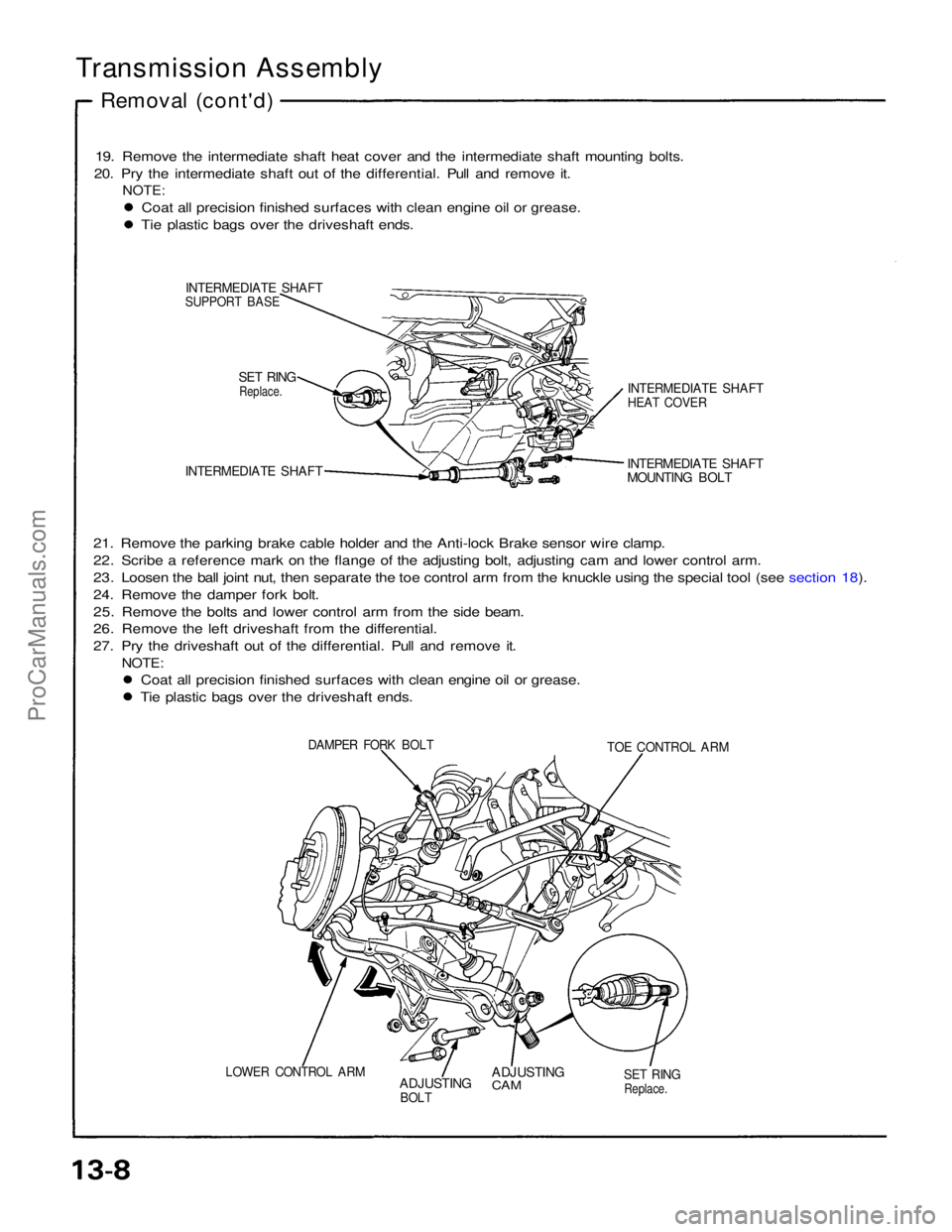
Transmission Assembly
Removal (cont'd)
19. Remove the intermediate shaft heat cover and the intermediate shaft mounting bolts.
20. Pry the intermediate shaft out of the differential. Pull and remove it.
NOTE:
Coat all precision finished surfaces with clean engine oil or grease. Tie plastic bags over the driveshaft ends.
INTERMEDIATE SHAFT
SUPPORT BASE
SET RING
Replace.
INTERMEDIATE SHAFT
21. Remove the parking brake cable holder and the Anti-lock Brake sensor wire clamp.
22. Scribe a reference mark on the flange of the adjusting bolt, adjusting cam and lower control arm.
23. Loosen the ball joint nut, then separate the toe control arm from the knuckle using the special tool (see section 18).
24. Remove the damper fork bolt.
25. Remove the bolts and lower control arm from the side beam.
26. Remove the left driveshaft from the differential.
27. Pry the driveshaft out of the differential. Pull and remove it.
NOTE:
Coat all precision finished surfaces with clean engine oil or grease.
Tie plastic bags over the driveshaft ends.
INTERMEDIATE SHAFT
MOUNTING BOLT
INTERMEDIATE SHAFT
HEAT COVER
DAMPER FORK BOLT
TOE CONTROL ARM
LOWER CONTROL ARM
ADJUSTING
BOLT
ADJUSTING
CAM
SET RING
Replace.
ProCarManuals.com