Page 1178 of 1640
Description
Electronic Control System (cont'd)
TRANSMISSION CONTROL MODULE (TCM)
ENGINE
CONTROL
MODULE
(ECM) Shift Control
Lock-up
Control
TCS Control Unit
EPS Control Unit Engine RPM
Air Conditioning Signal Brake Switch Signal
Vehicle Speed Sensor Signal
Mainshaft Speed Sensor Signal
Countershaft Speed Sensor Signal
Self-Diagnosis
Function
Self-Diagnosis Indicator
INTERLOCK
CONTROL UNIT
Lock-up Control Solenoid
Valve B
Lock-up Control Solenoid
Valve A Shift Control Solenoid
Valve B
Shift Control Solenoid
Valve A
Linear Solenoid
Throttle Position
Sensor Signal
Engine Coolant
Temperature
Sensor Signal
Accet Pedal
Angle Signal
Service Check
Connector
ProCarManuals.com
Page 1221 of 1640
Road Test
NOTE:
Warm up the engine to normal operating temperature (the cooling fan comes on).
When the engine coolant temperature is below normal operating temperature, the shift point is higher than specifiedvehicle speed.
Range 1. Apply parking brake and block the wheels. Start the engine, then move the selector to while depressing the brake
pedal. Depress the accelerator pedal, and release it suddenly. Engine should not stall.
2. Check that shift points occur at approximate speeds shown. Also check for abnormal noise and clutch slippage.
NOTE: Throttle position sensor voltage represents the throttle opening.
DIGITAL MULTIMETER
KS–AHM–32–003
ECM
TEST HARNESS
07LAJ–PT3010A
1. Connect the Test Harness between the ECM and connector (see section 11).
2. Set the digital multimeter to check voltage between D11 (+) terminal and D22 (-) terminal for the throttle posi- tion sensor.ProCarManuals.com
Page 1230 of 1640
(cont'd)
11. Remove the parking brake cable holders from the rear beam rod.
12. Remove the rear beam rod.
13. Remove the front exhaust pipe A.
PARKING BRAKE
CABLE HOLDER
PARKING BRAKE
CABLE
Corrosion resistant bolt/nut
Replace.
SELF-LOCKING NUT
REAR BEAM ROD
GASKET
Replace.
SELF-LOCKING NUT
Replace.
FRONT EXHAUST
PIPE A
14. Remove the parking brake cable holder and the wheel sensor wire clamp.
15. Make a reference mark on the flange of the adjusting bolt, adjusting cam and lower control arm.
16. Separate the toe control arm from the side beam.
17. Remove the damper fork bolt.
18. Separate the lower control arm from the side beam.
19. Remove the right driveshaft from the intermediate shaft.
DAMPER FORK BOLT
PARKING BRAKE
CABLE HOLDER
WHEEL SENSOR
WIRE CLAMP
LOWER CONTROL ARM
SELF-LOCKING NUT
Replace.
SIDE BEAM
TOE CONTROL ARM
SELF-LOCKING
NUT
Replace.
ADJUSTING BOLT
ADJUSTING CAM
Corrosion resistant bolt/nutProCarManuals.com
Page 1231 of 1640
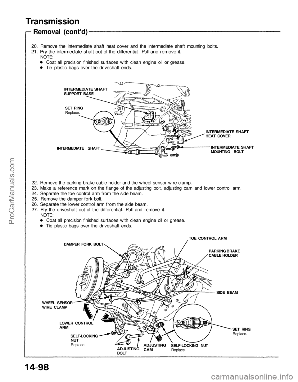
Transmission
Removal (cont'd)
20. Remove the intermediate shaft heat cover and the intermediate shaft mounting bolts.
21. Pry the intermediate shaft out of the differential. Pull and remove it.
NOTE:
INTERMEDIATE SHAFT
INTERMEDIATE SHAFT
HEAT COVER
INTERMEDIATE SHAFT
MOUNTING BOLT
SET RING
Replace.
INTERMEDIATE SHAFT
22. Remove the parking brake cable holder and the wheel sensor wire clamp.
23. Make a reference mark on the flange of the adjusting bolt, adjusting cam and lower control arm.
24. Separate the toe control arm from the side beam.
25. Remove the damper fork bolt.
26. Separate the lower control arm from the side beam.
27. Pry the driveshaft out of the differential. Pull and remove it.
NOTE:
TOE CONTROL ARM
DAMPER FORK BOLT
PARKING BRAKE
CABLE HOLDER
SIDE BEAM
SET RING
Replace.
SELF-LOCKING NUT
Replace.
ADJUSTING
CAM
ADJUSTING
BOLT
SELF-LOCKING
NUT
Replace.
LOWER CONTROL
ARM
WHEEL SENSOR
WIRE CLAMP
SUPPORT BASE
Coat all precision finished surfaces with clean engine oil or grease.
Tie plastic bags over the driveshaft ends.
Coat all precision finished surfaces with clean engine oil or grease.
Tie plastic bags over the driveshaft ends.ProCarManuals.com
Page 1234 of 1640
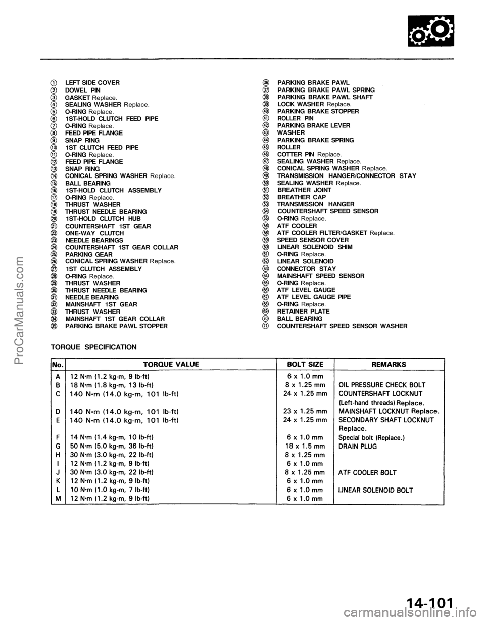
LEFT SIDE COVER
DOWEL PIN
GASKET Replace.
SEALING WASHER
Replace.
O-RING
Replace.
1ST-HOLD CLUTCH FEED PIPE
O-RING
Replace.
FEED PIPE FLANGE
SNAP RING
1ST CLUTCH FEED PIPE
O-RING
Replace.
FEED PIPE FLANGE
SNAP RING
CONICAL SPRING WASHER
Replace.
BALL BEARING
1ST-HOLD CLUTCH ASSEMBLY
O-RING
Replace.
THRUST WASHER
THRUST NEEDLE BEARING
1ST-HOLD CLUTCH HUB
COUNTERSHAFT 1ST GEAR
ONE-WAY CLUTCH NEEDLE BEARINGS
COUNTERSHAFT 1ST GEAR COLLAR
PARKING GEAR
CONICAL SPRING WASHER
Replace.
1ST CLUTCH ASSEMBLY
O-RING
Replace.
THRUST WASHER
THRUST NEEDLE BEARING
NEEDLE BEARINGMAINSHAFT 1ST GEAR
THRUST WASHER MAINSHAFT 1ST GEAR COLLAR
PARKING BRAKE PAWL STOPPER PARKING BRAKE PAWL
PARKING BRAKE PAWL SPRING
PARKING BRAKE PAWL SHAFT
LOCK WASHER
Replace.
PARKING BRAKE STOPPER
ROLLER PIN
PARKING BRAKE LEVER
WASHER
PARKING BRAKE SPRING
ROLLER
COTTER PIN
Replace.
SEALING WASHER
Replace.
CONICAL SPRING WASHER
Replace.
TRANSMISSION HANGER/CONNECTOR STAY
SEALING WASHER
Replace.
BREATHER JOINT
BREATHER CAP
TRANSMISSION HANGER COUNTERSHAFT SPEED SENSOR
O-RING
Replace.
ATF COOLER
ATF COOLER FILTER/GASKET
Replace.
SPEED SENSOR COVER
LINEAR SOLENOID SHIM
O-RING
Replace.
LINEAR SOLENOID
CONNECTOR STAY
MAINSHAFT SPEED SENSOR
O-RING
Replace.
ATF LEVEL GAUGE
ATF LEVEL GAUGE PIPE
O-RING
Replace.
RETAINER PLATE
BALL BEARING
COUNTERSHAFT SPEED SENSOR WASHER
TORQUE SPECIFICATIONProCarManuals.com
Page 1239 of 1640
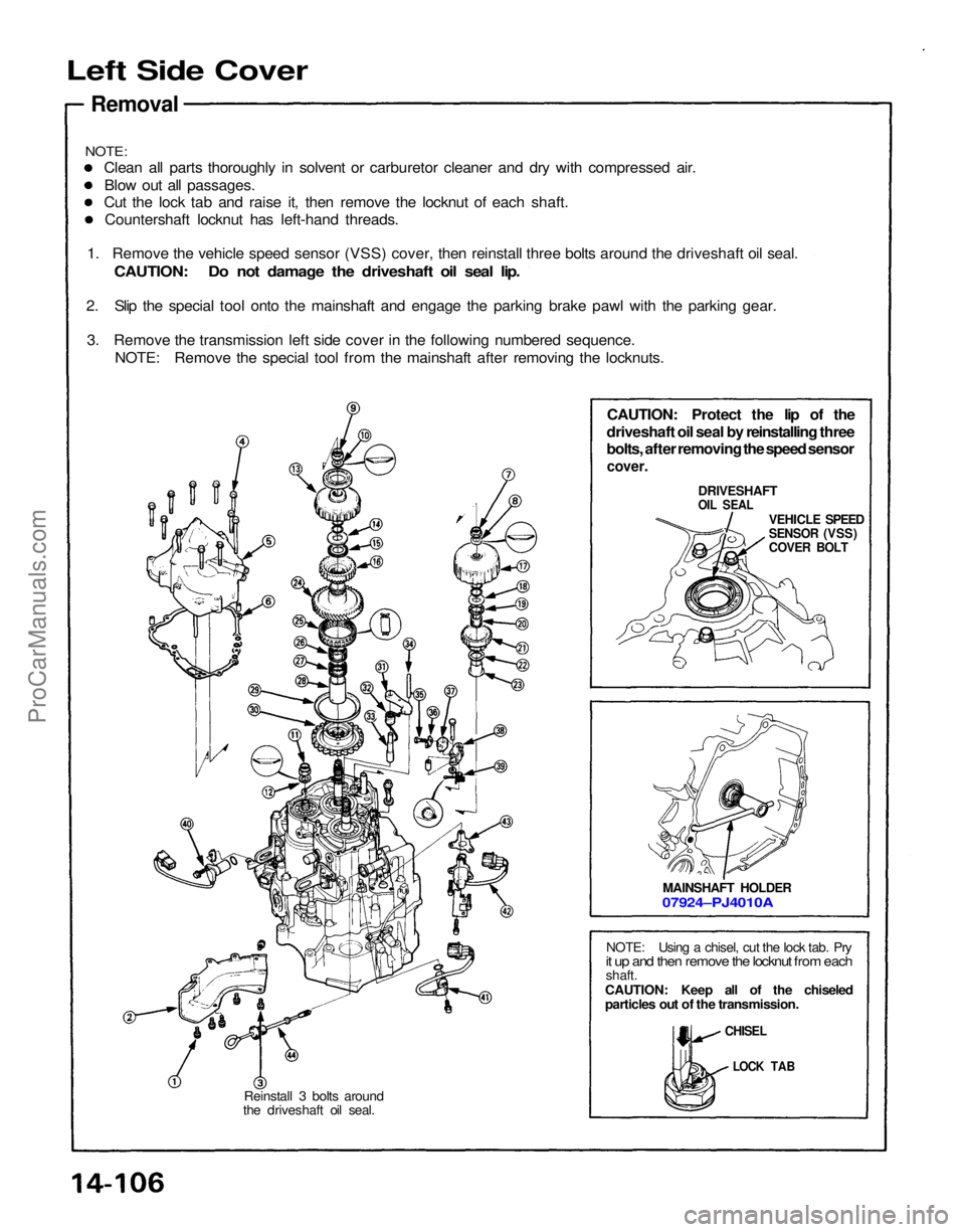
Left Side Cover
Removal
CAUTION: Protect the lip of the
driveshaft oil seal by reinstalling three
bolts, after removing the speed sensor
cover.
DRIVESHAFT
OIL SEAL
VEHICLE SPEED
SENSOR (VSS)
COVER BOLT
MAINSHAFT HOLDER
07924–PJ4010A
NOTE: Using a chisel, cut the lock tab. Pry
it up and then remove the locknut from each
shaft.
CAUTION: Keep all of the chiseled
particles out of the transmission.
CHISEL
LOCK TAB
Reinstall 3 bolts around
the driveshaft oil seal.
NOTE:
Clean all parts thoroughly in solvent or carburetor cleaner and dry with compressed air.
Blow out all passages.
Cut the lock tab and raise it, then remove the locknut of each shaft.
Countershaft locknut has left-hand threads.
1. Remove the vehicle speed sensor (VSS) cover, then reinstall three bolts around the driveshaft oil seal.
CAUTION: Do not damage the driveshaft oil seal lip.
2. Slip the special tool onto the mainshaft and engage the parking brake pawl with the parking gear.
3. Remove the transmission left side cover in the following numbered sequence. NOTE: Remove the special tool from the mainshaft after removing the locknuts.ProCarManuals.com
Page 1287 of 1640
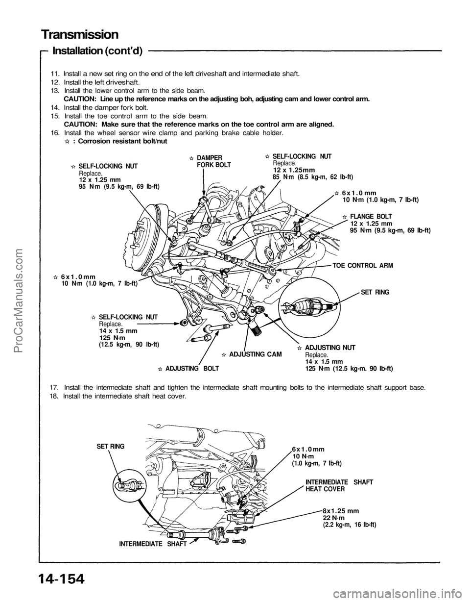
Transmission
Installation (cont'd)
11. Install a new set ring on the end of the left driveshaft and intermediate shaft.
12. Install the left driveshaft.
13. Install the lower control arm to the side beam. CAUTION: Line up the reference marks on the adjusting boh, adjusting cam and lower control arm.
14. Install the damper fork bolt.
15. Install the toe control arm to the side beam. CAUTION: Make sure that the reference marks on the toe control arm are aligned.
16. Install the wheel sensor wire clamp and parking brake cable holder.
SELF-LOCKING NUTReplace.
12 x
1.25
mm
95 N .
m (9.5 kg-m, 69 Ib-ft) DAMPER
FORK BOLT
SELF-LOCKING NUT
Replace.
12 x 1.25mm
85 N .
m (8.5 kg-m, 62 Ib-ft)
6x1.0
mm
10 N .
m (1.0 kg-m, 7 Ib-ft)
FLANGE BOLT
12 x
1.25
mm
95 N .
m (9.5 kg-m, 69 Ib-ft)
TOE CONTROL ARM SET RING
6x1.0
mm
Replace. SELF-LOCKING NUT
ADJUSTING NUT
Replace.
14 x 1.5 mm
125 N .
m (12.5 kg-m. 90 Ib-ft)
ADJUSTING CAM
ADJUSTING BOLT
17. Install the intermediate shaft and tighten the intermediate shaft mounting bolts to the intermediate shaft support base.
18. Install the intermediate shaft heat cover.
6x1.0
mm
10 N·m
(1.0 kg-m, 7 Ib-ft)
INTERMEDIATE SHAFT
HEAT COVER
8x1.25 mm
22 N·m
(2.2 kg-m, 16 Ib-ft)
INTERMEDIATE SHAFT
SET RING
Corrosion resistant bolt/nut
10 N .
m (1.0 kg-m, 7 Ib-ft)
14 x 1.5 mm
125 N .
m
(12.5 kg-m, 90 Ib-ft)ProCarManuals.com
Page 1288 of 1640
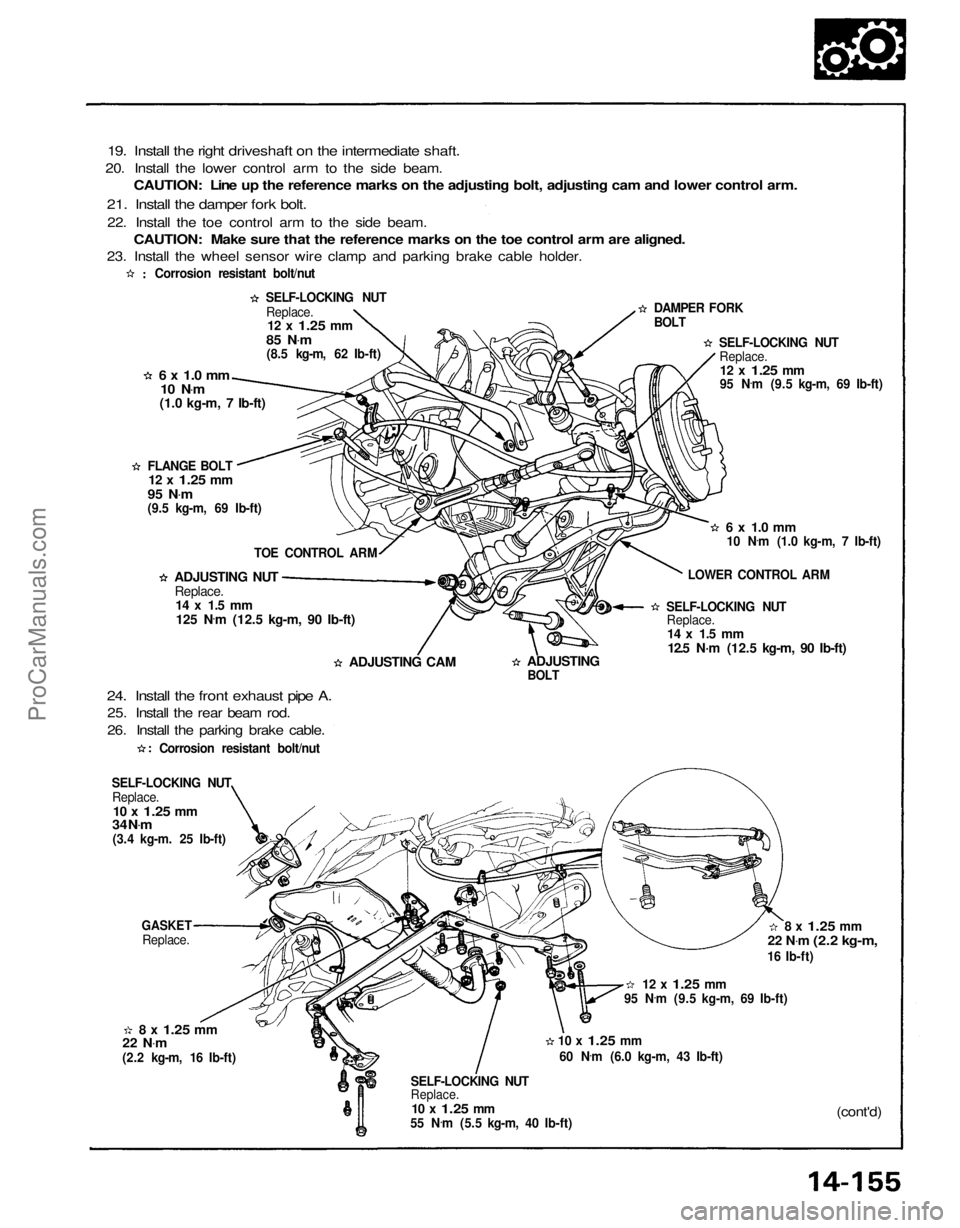
19. Install the right driveshaft on the intermediate shaft.
20. Install the lower control arm to the side beam. CAUTION: Line up the reference marks on the adjusting bolt, adjusting cam and lower control arm.
21. Install the damper fork bolt.
22. Install the toe control arm to the side beam. CAUTION: Make sure that the reference marks on the toe control arm are aligned.
23. Install the wheel sensor wire clamp and parking brake cable holder.
Corrosion resistant bolt/nut
SELF-LOCKING NUT DAMPER FORK
BOLT
SELF-LOCKING NUTReplace.
12 x
1.25
mm
95 N .
m (9.5 kg-m, 69 Ib-ft)
6 x 1.0 mm
FLANGE BOLT
(cont'd)
SELF-LOCKING NUT
Replace.
10 x
1.25
mm
55 N .
m (5.5 kg-m, 40 Ib-ft)
10 x
1.25
mm
60 N .
m (6.0 kg-m, 43 Ib-ft) 95 N
.
m (9.5 kg-m, 69 Ib-ft)
12 x
1.25
mm
22 N
.
m
(2.2 kg-m,
16 Ib-ft)
8 x
1.25
mm
22 N .
m
(2.2 kg-m, 16 Ib-ft)
8 x
1.25
mm
GASKET
Replace.
SELF-LOCKING NUT
Replace.
10 x
1.25
mm
34 N .
m
(3.4 kg-m. 25 Ib-ft)
24. Install the front exhaust pipe A.
25. Install the rear beam rod.
26. Install the parking brake cable.
ADJUSTING CAM
125 N
.
m (12.5 kg-m, 90 Ib-ft)
ADJUSTING NUT
Replace.
14 x 1.5 mm
TOE CONTROL ARM
95 N
.
m
(9.5 kg-m, 69 Ib-ft) Replace.
12 x
1.25
mm
85 N .
m
(8.5 kg-m, 62 Ib-ft)
10 N .
m
(1.0 kg-m, 7 Ib-ft)
12 x
1.25
mm
Corrosion resistant bolt/nut
ADJUSTING
BOLT
SELF-LOCKING NUT
Replace.
14 x 1.5 mm
12.5 N·m (12.5 kg-m, 90 Ib-ft)
LOWER CONTROL ARM
6 x 1.0 mm
10 N .
m (1.0 kg-m, 7 Ib-ft)ProCarManuals.com