Page 1552 of 1640

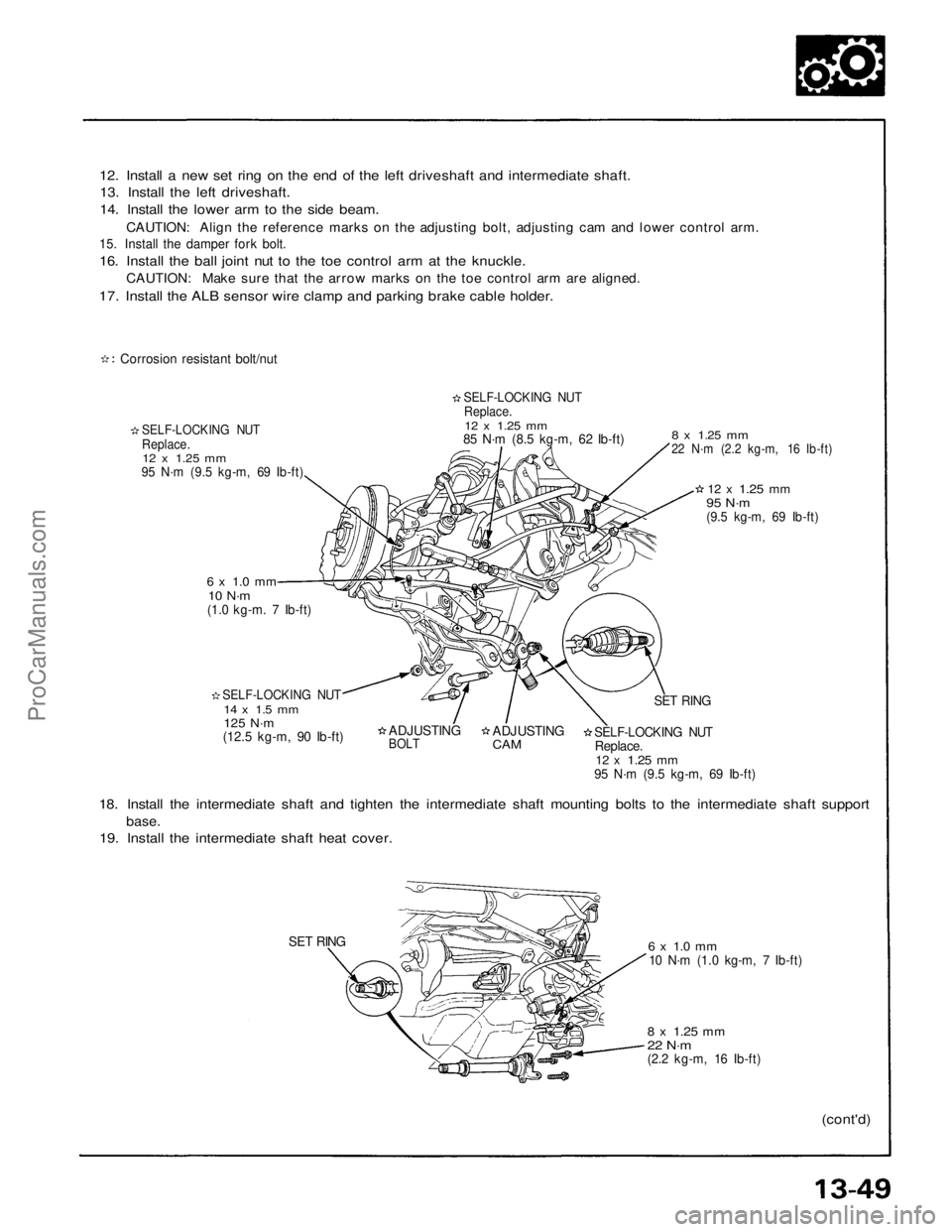
12. Install a new set ring on the end of the left driveshaft and intermediate shaft.
13. Install the left driveshaft.
14. Install the lower arm to the side beam.
CAUTION: Align the reference marks on the adjusting bolt, adjusting cam and lower control arm.
15. Install the damper fork bolt.
16. Install the ball joint nut to the toe control arm at the knuckle.
CAUTION: Make sure that the arrow marks on the toe control arm are aligned.
17. Install the ALB sensor wire clamp and parking brake cable holder.
Corrosion resistant bolt/nut
SELF-LOCKING NUT
Replace.
12 x
1.25
mm
95 N·m (9.5 kg-m, 69 Ib-ft)
SELF-LOCKING NUT
Replace.
12 x
1.25
mm
85 N·m (8.5 kg-m, 62 Ib-ft)
6 x 1.0 mm
10 N·m
(1.0 kg-m. 7 Ib-ft)
SELF-LOCKING NUT
14 x 1.5 mm
125 N·m
(12.5 kg-m, 90 Ib-ft)
8 x
1.25
mm
22 N·m (2.2 kg-m, 16 Ib-ft)
12 x
1.25
mm
95 N·m
(9.5 kg-m, 69 Ib-ft)
ADJUSTING
BOLT
ADJUSTING
CAM
SET RING
SELF-LOCKING NUT
Replace.
12 x
1.25
mm
95 N·m (9.5 kg-m, 69 Ib-ft)
18. Install the intermediate shaft and tighten the intermediate shaft mounting bolts to the intermediate shaft support
base.
19. Install the intermediate shaft heat cover.
SET RING
6 x 1.0 mm
10 N·m (1.0 kg-m, 7 Ib-ft)
8 x
1.25
mm
22 N·m
(2.2 kg-m, 16 Ib-ft)
(cont'd)ProCarManuals.com
Page 1553 of 1640

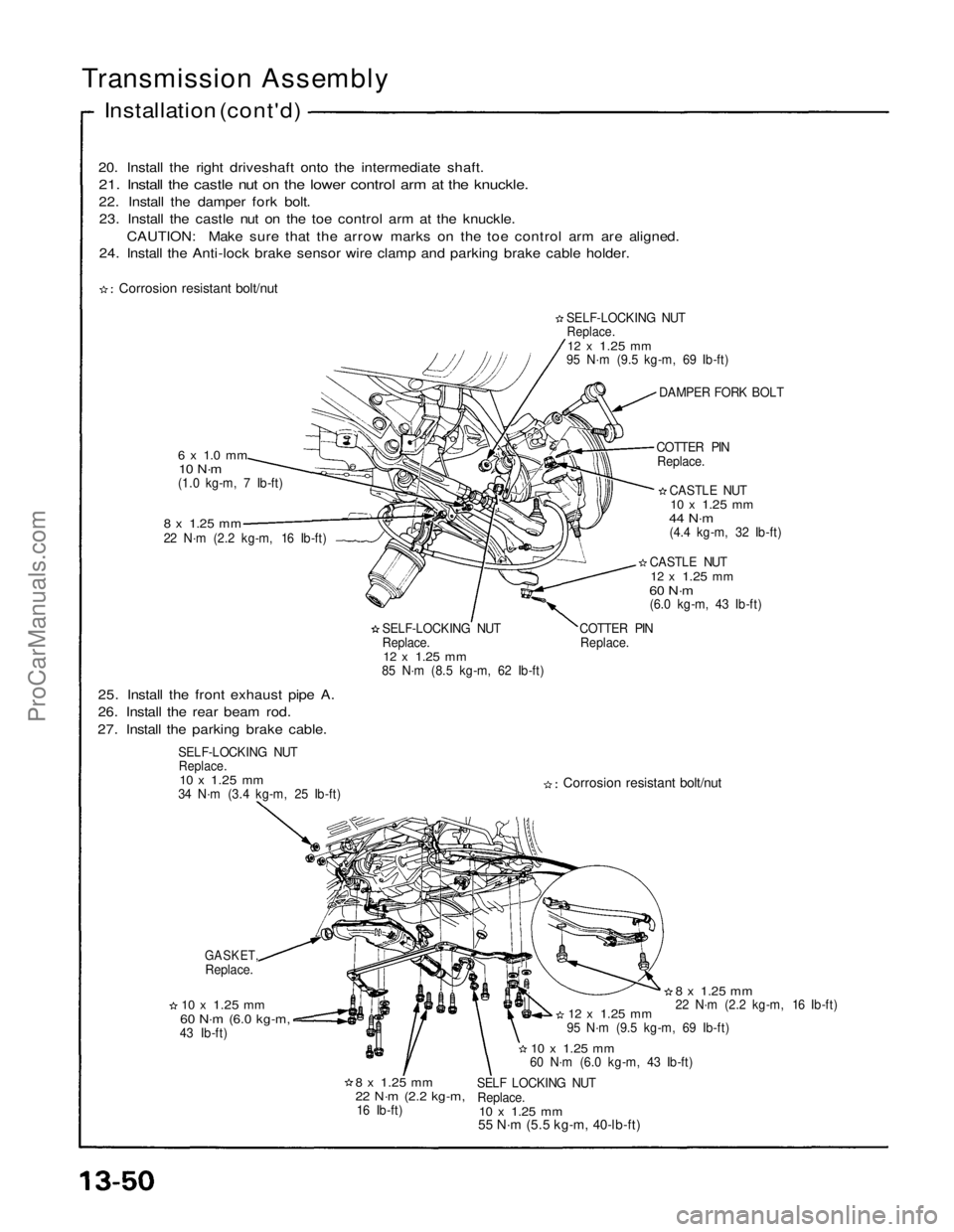
20. Install the right driveshaft onto the intermediate shaft.
21. Install the castle nut on the lower control arm at the knuckle.
22. Install the damper fork bolt.23. Install the castle nut on the toe control arm at the knuckle.
CAUTION: Make sure that the arrow marks on the toe control arm are aligned.
24. Install the Anti-lock brake sensor wire clamp and parking brake cable holder.
Transmission Assembly
Installation (cont'd)
Corrosion resistant bolt/nut
6 x 1.0 mm
10 N·m
(1.0 kg-m, 7 Ib-ft)
8 x
1.25
mm
22 N·m (2.2 kg-m, 16 Ib-ft)
SELF-LOCKING NUT
Replace.
12 x
1.25
mm
85 N·m (8.5 kg-m, 62 Ib-ft) COTTER PIN
Replace. CASTLE NUT
12 x
1.25
mm
60 N·m
(6.0 kg-m, 43 Ib-ft) CASTLE NUT
10 x
1.25
mm
44 N·m
(4.4 kg-m, 32 Ib-ft)
COTTER PIN
Replace. DAMPER FORK BOLT
SELF-LOCKING NUT
Replace.
12 x
1.25
mm
95 N·m (9.5 kg-m, 69 Ib-ft)
25. Install the front exhaust pipe A.
26. Install the rear beam rod.
27. Install the parking brake cable.
SELF-LOCKING NUT
Replace.
10 x
1.25
mm
34 N·m (3.4 kg-m, 25 Ib-ft)
Corrosion resistant bolt/nut
GASKET,
Replace.
10 x
1.25
mm
60 N·m
(6.0 kg-m,
43 Ib-ft)
8 x
1.25
mm
22 N·m
(2.2 kg-m,
16 Ib-ft) SELF LOCKING NUT
Replace.
10 x
1.25
mm
55 N·m (5.5 kg-m, 40-lb-ft)
10 x
1.25
mm
60 N·m (6.0 kg-m, 43 Ib-ft)
12 x
1.25
mm
95 N·m (9.5 kg-m, 69 Ib-ft)
8 x
1.25
mm
22 N·m (2.2 kg-m, 16 Ib-ft)ProCarManuals.com
Page 1585 of 1640

Supplemental Restraint System (SRS)
Self-diagnosis Function
The SRS unit includes a self-diagnosis function. If there
is a failure in the sensors, SRS unit, inflator, or their cir-
cuits, the SRS light in the instrument panel goes ON.
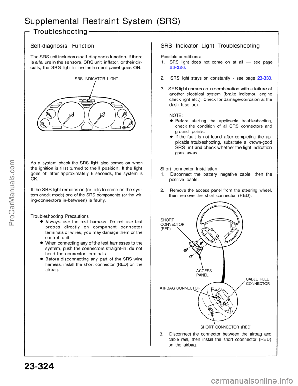
SRS INDICATOR LIGHT
As a system check the SRS light also comes on when
the ignition is first turned to the II position. If the light
goes off after approximately 6 seconds, the system is
OK.
If the SRS light remains on (or fails to come on the sys-
tem check mode) one of the SRS components (or the wir-
ing/connectors in-between) is faulty.
Troubleshooting Precautions Always use the test harness. Do not use test
probes directly on component connector
terminals or wires; you may damage them or the
control unit. When connecting any of the test harnesses to the
system, push the connectors straight-in; do not
bend the connector terminals. Before disconnecting any part of the SRS wire
harness, install the short connector (RED) on the airbag. SRS Indicator Light Troubleshooting
Possible conditions: 1. SRS light does not come on at all — see page
23-326.
2. SRS light stays on constantly - see page 23-330.
3. SRS light comes on in combination with a failure of
another electrical system (brake indicator, engine
check light etc.). Check for damage/corrosion at the
dash fuse box.
NOTE:
Before starting the applicable troubleshooting,
check the condition of all SRS connectors and
ground points. If the fault is not found after completing the ap-
plicable troubleshooting, substitute a known-good
SRS unit and check whether the light indication
goes away.
Short connector Installation 1. Disconnect the battery negative cable, then the positive cable.
2. Remove the access panel from the steering wheel, then remove the short connector (RED).
SHORT
CONNECTOR
(RED)
3. Disconnect the connector between the airbag and cable reel, then install the short cconnector (RED)
on the airbag.
Troubleshooting
SHORT CONNECTOR (RED)
AIRBAG CONNECTOR
CABLE REEL
CONNECTOR
ACCESS
PANELProCarManuals.com