1991 ACURA NSX brake sensor
[x] Cancel search: brake sensorPage 860 of 1640
(G551) '95-'96 Models.
(G401,G402,G551) '93-94 Models or
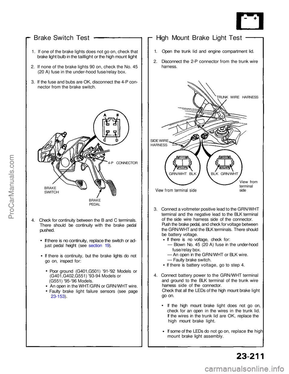
Brake Switch
Test
1
.
If one of the brake lights does not go on, check that
brake
light bulb in the taillight or the high mount light
2
.
If none of the brake lights 90 on, check the No. 45 (2
0
A) fuse in the under-hood fuse/relay box.
3
.
If the fuse and bubs are OK, disconnect the 4-P con- necto
r
from the brake switch.
4-P CONNECTOR
BRAKE
SWITCH
BRAKE
PEDAL
4. Check for continuity between the B and C terminals. There should be continuity with the brake pedal
pushed.
If there is no continuity, replace the switch or ad-
just pedal height (see section 19).
If there is continuity, but the brake lights do not
go on, inspect for:
Poor ground (G401,G501) '91-'92 Models or
An open in the WHT/GRN or GRN/WHT wire. Faulty brake light failure sensors (see page 23-153). High Mount Brake Light Test
1. Open the trunk lid and engine compartment lid.
2. Disconnect the 2-P connector from the trunk wire
harness.
TRUNK WIRE HARNESS
SIDE WIRE
HARNESS
View from terminal side
View from
terminal
side
3. Connect a voltmeter positive lead to the GRN/WHT terminal and the negative lead to the BLK terminalof the side wire harness side of the connector.
Push the brake pedal, and check for voltage between
the GRN/WHT and the BLK terminals. There should be battery voltage. If there is no voltage, check for:
— Blown No. 45 (20 A) fuse in the under-hood
fuse/relay box.
— An open in the GRN/WHT or BLK wire.
— Faulty brake switch.
If there is battery voltage, go to step 4.
4. Connect battery power to the GRN/WHT terminal and ground to the BLK terminal of the trunk wireharness side of the connector.
Check that all the LEDs of the high mount brake light
go on.
If the high mount brake light does not go on,check for an open in the wires
in the trunk lid.
If the wires in the trunk lid are OK, replace the
high mount brake light.
If some of the LEDs do not go on,
replace the high
mount brake light assembly.
GRN/WHT BLK
BLK GRN/WHTProCarManuals.com
Page 935 of 1640
Cruise Control
Description
The cruise control system uses mechanically and electri-
cally operated devices to maintain vehicle speed at a
setting selected by the driver.
The ECM receives command signals from the cruise con-
trol main switch and the cruise control set/resume switch.
It receives information about operating conditions from
the brake switch, vehicle speed sensor (VSS), the clutch
switch (with manual transmission), or the A/T gear posi-
tion switch (with automatic transmission). The ECM
sends operational signals to the devices that regulate the
throttle position. The throttle position maintains the
selected vehicle speed. Essentially, the ECM compares
the actual speed of the vehicle to the selected speed.
Then, it uses the result of that comparison to open or
close the throttle.
The brake switch releases the system's control of the
throttle at the instant the driver depresses the brake
pedal. The switch sends an electronic signal to the ECM
when the brake pedal is depressed; the ECM responds
by allowing the throttle to close. The clutch switch (man-
ual transmission) or the A/T gear position switch (auto-
matic transmission) sends a disengage signal to the
ECM that also allows the throttle to close.
Operation:
The cruise control system will set and automatically
maintain any speed above 25 mph (45 km/h). To set,
make sure that the main switch is in the "ON" position.
After reaching the desired speed, press the set switch.
The ECM will receive a set signal and, in turn, will actu-
ate the throttle valve control motor. When the set switch
is depressed and the cruise control system is on, the
"cruise control" ON indicator in the gauge assembly will
light up. You can cancel the cruise control system by
pushing the main switch to "OFF". This erases the set
speed from memory. If the system is disengaged tem-
porarily by the brake switch, clutch switch, or A/T gear
position switch and vehicle speed is still above 25 mph,
press the resume switch. With the resume switch
depressed and the set memory retained, the vehicle
automatically returns to the previous set speed.
For gradual acceleration without depressing the acceler-
ator pedal, push the resume switch down and hold it
there until the desired speed is reached. This will send
an acceleration signal to the ECM. When the switch is
released, the system will be reprogrammed for the new
speed. To slow down, depress the set switch. This will
send a deceleration signal to the ECM causing the car to
coast until the desired speed is reached. When the
desired speed is reached, release the set switch. This
will reprogram the system for the new speed.ProCarManuals.com
Page 992 of 1640
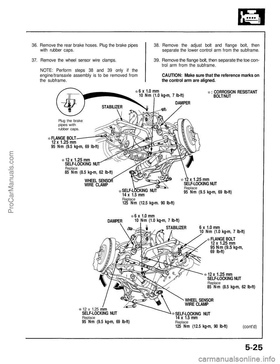
36. Remove the rear brake hoses. Plug the brake pipes
with rubber caps.
37. Remove the wheel sensor wire clamps. NOTE: Perform steps 38 and 39 only if the
engine/transaxle assembly is to be removed from
the subframe. 38. Remove the adjust bolt and flange bolt, then
separate the lower control arm from the subframe.
39. Remove the flange bolt, then separate the toe con-
trol arm from the subframe.
CAUTION: Make sure that the reference marks on
the control arm are aligned.
: CORROSION RESISTANTBOLT/NUT
6 x 1.0 mm
10 N .
m (1.0 kg-m, 7 Ib-ft)
DAMPER
STABILIZER
Plug the brake
pipes with
rubber caps.
FLANGE BOLT
12 x
1.25
mm
95 N .
m (9.5 kg-m, 69 Ib-ft)
12 x
1.25
mm
SELF-LOCKING NUT
Replace
85 N .
m (8.5 kg-m, 62 Ib-ft)
WHEEL SENSOR
WIRE CLAMP
SELF-LOCKING NUT
14 x 1.5 mm
Replace
125 N .
m (12.5 kg-m. 90 Ib-ft)
12 x
1.25
mm
SELF-LOCKING NUT
Replace
95 N .
m (9.5 kg-m, 69 Ib-ft)
DAMPER
6 x 1.0 mm
10 N .
m (1.0 kq-m, 7 Ib-ft)
STABILIZER
6 x 1.0 mm
10 N .
m (1.0 kg-m, 7 Ib-ft)
FLANGE BOLT
12 x
1.25
mm
95 N·m
(9.5
kg-m,
69 Ib-ft)
12 x
1.25
mm
SELF-LOCKING NUT
Replace
85 N·m (8.5 kg-m, 62 Ib-ft)
WHEEL SENSOR
WIRE CLAMP
SELF-LOCKING NUT
14 x 1.5 mm
Replace
125 N .
m (12.5 kg-m, 90 Ib-ft)
(cont'd)
12 x
1.25
mm
SELF-LOCKING NUT
Replace
95 N .
m (9.5 kg-m, 69 Ib-ft)ProCarManuals.com
Page 1015 of 1640
14. Relieve fuel pressure (see section 11).
Do not smoke while working on fuel
system; keep open flame or spark away from work
area. Drain fuel only into an approved container.
1 5. Disconnect the fuel feed pipe and the return hose
(page 5-21).
16. Remove the ignition coil covers, the wire harness covers, the ignition coils and the connectors (page
6-23).
17. Remove the water hoses, then remove the expan- sion tank (page 5-21).
18. Remove the breather hose, and the air cleaner housing (page 5-22).
19. Remove the brake booster hose, the evaporative emission (EVAP) control canister hose and other
hoses from the intake manifold and throttle body
(page 5-22).
20. Remove the emission control box (page 5-23). Do not disconnect emission hose.Disconnect the three connectors before
removing.
21. Remove the connector, the terminal and the alternator.
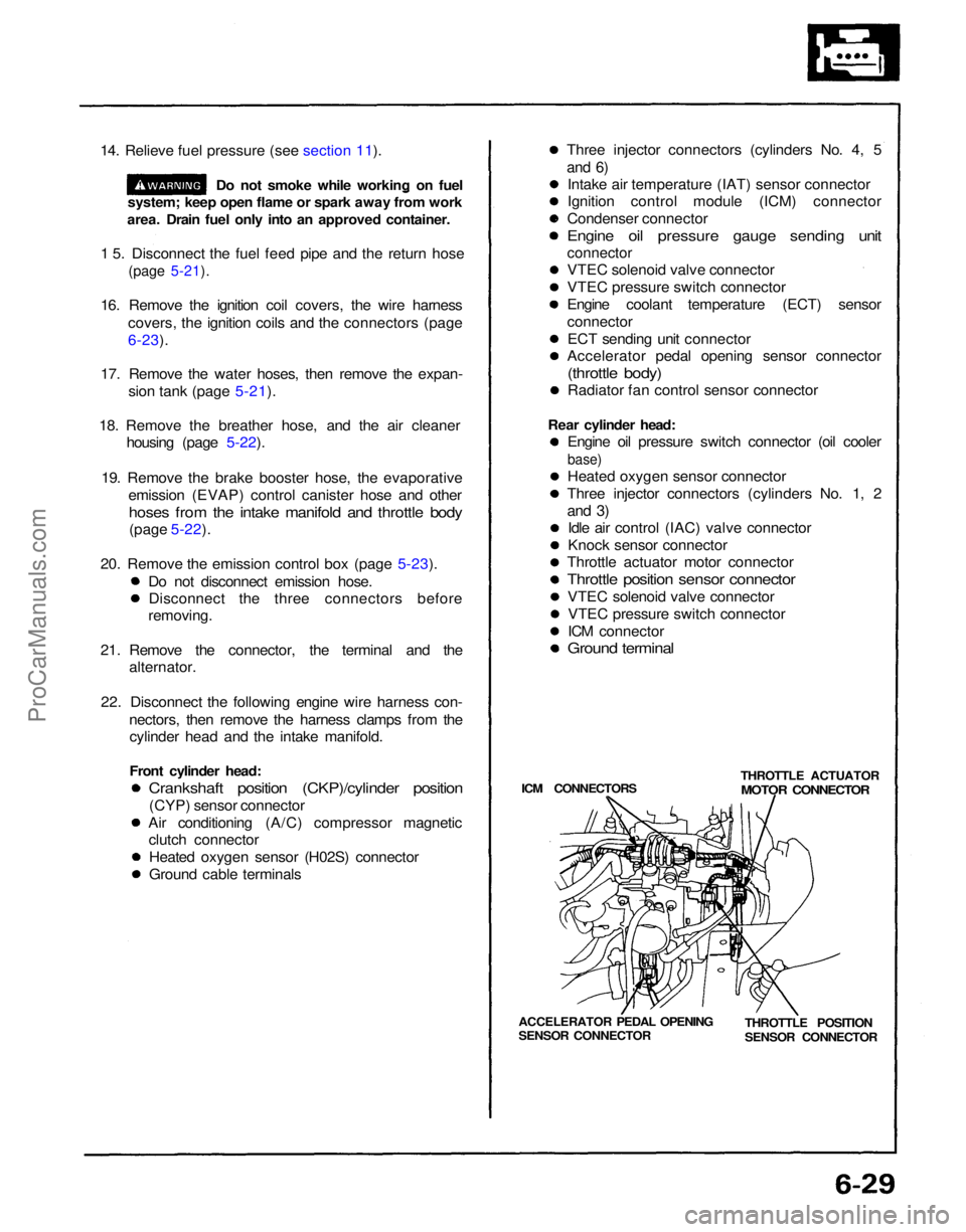
22. Disconnect the following engine wire harness con- nectors, then remove the harness clamps from thecylinder head and the intake manifold.
Front cylinder head:
Crankshaft position (CKP)/cylinder position
(CYP) sensor connector
Air conditioning (A/C) compressor magnetic clutch connector
Heated oxygen sensor (H02S) connector
Ground cable terminals Three injector connectors (cylinders No. 4, 5
and 6)
Intake air temperature (IAT) sensor connector
Ignition control module (ICM) connector
Condenser connector
Engine oil pressure gauge sending unit
connector
VTEC solenoid valve connector
VTEC pressure switch connector
Engine coolant temperature (ECT) sensor
connector
ECT sending unit connector
Accelerator pedal opening sensor connector
(throttle body)
Radiator fan control sensor connector
Rear cylinder head: Engine oil pressure switch connector (oil cooler
base)
Heated oxygen sensor connector
Three injector connectors (cylinders No. 1, 2
and 3)
Idle air control (IAC) valve connector
Knock sensor connector
Throttle actuator motor connector
Throttle position sensor connector
VTEC solenoid valve connectorVTEC pressure switch connector
ICM connector
Ground terminal
ICM CONNECTORS THROTTLE ACTUATOR
MOTOR CONNECTOR
THROTTLE POSITION
SENSOR CONNECTOR
ACCELERATOR PEDAL OPENING
SENSOR CONNECTORProCarManuals.com
Page 1149 of 1640
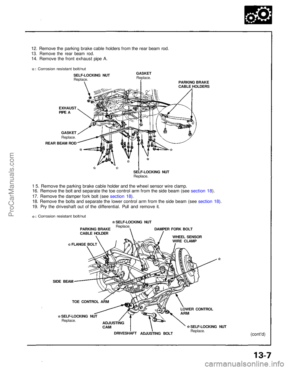
12. Remove the parking brake cable holders from the rear beam rod.
13. Remove the rear beam rod.
14. Remove the front exhaust pipe A.
Corrosion resistant bolt/nut
EXHAUST
PIPE ASELF-LOCKING NUT
Replace.
GASKET
Replace.
GASKET
Replace.
REAR BEAM ROD
1 5. Remove the parking brake cable holder and the wheel sensor wire clamp. 16. Remove the bolt and separate the toe control arm from the side beam (see section 18).
17. Remove the damper fork bolt (see section 18). 18. Remove the bolts and separate the lower control arm from the side beam (see section 18).
19. Pry the driveshaft out of the differential. Pull and remove it. SELF-LOCKING NUT
Replace.
PARKING BRAKE
CABLE HOLDERS
PARKING BRAKE
CABLE HOLDER
FLANGE BOLT
SIDE BEAM TOE CONTROL ARM
SELF-LOCKING NUT Replace. SELF-LOCKING NUT
Replace.
WHEEL SENSOR
WIRE CLAMP
DAMPER FORK BOLT
ADJUSTING
CAM
DRIVESHAFT
ADJUSTING BOLT SELF-LOCKING NUT
Replace.
LOWER CONTROL
ARM
(cont'd)
Corrosion resistant bolt/nutProCarManuals.com
Page 1150 of 1640
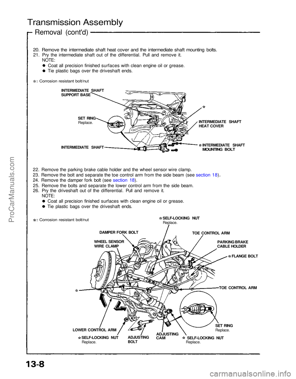
Transmission Assembly
Removal (cont'd)
20. Remove the intermediate shaft heat cover and the intermediate shaft mounting bolts.
21. Pry the intermediate shaft out of the differential. Pull and remove it.
NOTE:
Coat all precision finished surfaces with clean engine oil or grease.
Tie plastic bags over the driveshaft ends.
Corrosion resistant bolt/nut
INTERMEDIATE SHAFT
SUPPORT BASE
SET RINGReplace.
INTERMEDIATE SHAFT
22. Remove the parking brake cable holder and the wheel sensor wire clamp.
23. Remove the bolt and separate the toe control arm from the side beam (see section 18).
24. Remove the damper fork bolt (see section 18). 25. Remove the bolts and separate the lower control arm from the side beam.
26. Pry the driveshaft out of the differential. Pull and remove it.
NOTE:
Coat all precision finished surfaces with clean engine oil or grease.
Tie plastic bags over the driveshaft ends.
Corrosion resistant bolt/nut
DAMPER FORK BOLT
WHEEL SENSOR WIRE CLAMP
LOWER CONTROL ARM SELF-LOCKING NUTReplace. ADJUSTING
BOLT
ADJUSTING
CAM
SELF-LOCKING NUT
Replace.SET RING
Replace.TOE CONTROL ARM
PARKING BRAKE
CABLE HOLDER
FLANGE BOLT
TOE CONTROL ARM
SELF-LOCKING NUT
Replace. INTERMEDIATE SHAFT
MOUNTING BOLT
INTERMEDIATE SHAFT
HEAT COVERProCarManuals.com
Page 1161 of 1640
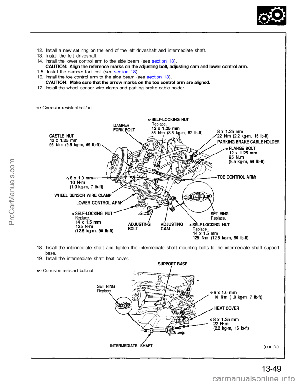
12. Install a new set ring on the end of the left driveshaft and intermediate shaft.
13. Install the left driveshaft.
14. Install the lower control arm to the side beam (see section 18).
CAUTION: Align the reference marks on the adjusting bolt, adjusting cam and lower control arm.
1 5. Install the damper fork bolt (see section 18).
16. Install the toe control arm to the side beam (see section 18).
CAUTION: Make sure that the arrow marks on the toe control arm are aligned.
17. Install the wheel sensor wire clamp and parking brake cable holder.
Corrosion resistant bolt/nut
CASTLE NUT
12 x
1.25
mm
95 N .
m (9.5 kg-m, 69 Ib-ft) DAMPER
FORK BOLT
6 x 1.0 mm
10 N .
m
(1.0 kg-m, 7 Ib-ft)
WHEEL SENSOR WIRE CLAMP LOWER CONTROL ARM
SELF-LOCKING NUT
Replace.
14 x 1.5 mm
125 N .
m
(12.5 kg-m. 90 Ib-ft)
ADJUSTING
BOLT
ADJUSTING
CAM
18. Install the intermediate shaft and tighten the intermediate shaft mounting bolts to the intermediate shaft support
base.
19. Install the intermediate shaft heat cover.
Corrosion resistant bolt/nut
SET RINGReplace.
13-49(cont'd)
INTERMEDIATE SHAFT
8 x
1.25
mm
22 N
.
m
(2.2 kg-m, 16 Ib-ft) HEAT COVER
6 x 1.0 mm
10 N .
m (1.0 kg-m. 7 Ib-ft)
SUPPORT BASE SELF-LOCKING NUT
Replace.
14 x 1.5 mm
125 N .
m (12.5 kg-m, 90 Ib-ft) SET RING
Replace. TOE CONTROL ARM
FLANGE BOLT
12 x
1.25
mm
95 N.m
(9.5 kg-m, 69 Ib-ft)
8 x
1.25
mm
22 N
.
m (2.2 kg-m, 16 Ib-ft)
PARKING BRAKE CABLE HOLDER
SELF-LOCKING NUT
Replace.
12 x
1.25
mm
85 N .
m (8.5 kg-m, 62 Ib-ft)ProCarManuals.com
Page 1162 of 1640
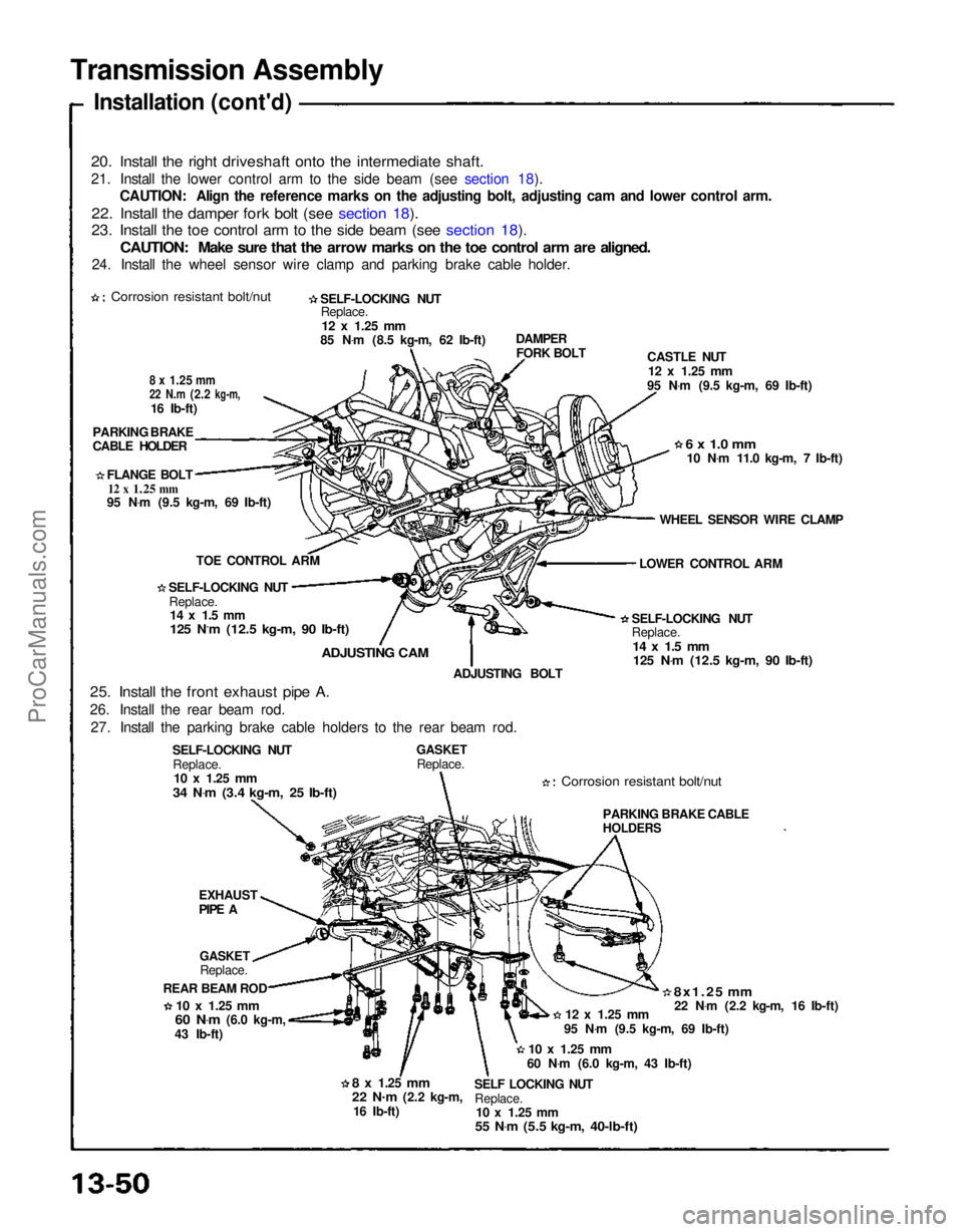
Transmission Assembly
Installation (cont'd)
20. Install the right driveshaft onto the intermediate shaft.
21. Install the lower control arm to the side beam (see section 18). CAUTION: Align the reference marks on the adjusting bolt, adjusting cam and lower control arm.
22. Install the damper fork bolt (see section 18).
23. Install the toe control arm to the side beam (see section 18).
CAUTION: Make sure that the arrow marks on the toe control arm are aligned.
24. Install the wheel sensor wire clamp and parking brake cable holder.
Corrosion resistant bolt/nut
SELF-LOCKING NUT
Replace.
12 x
1.25
mm
85 N .
m (8.5 kg-m, 62 Ib-ft)
8 x
1.25
mm
22 N.m
(2.2
kg-m,
16 Ib-ft)
PARKING BRAKE
CABLE HOLDER
FLANGE BOLT
12 x
1.25
mm
95 N .
m (9.5 kg-m, 69 Ib-ft)
TOE CONTROL ARM
SELF-LOCKING NUT Replace.
14 x 1.5 mm
125 N.m (12.5 kg-m, 90 Ib-ft)
ADJUSTING CAM
25. Install the front exhaust pipe A.
26. Install the rear beam rod. 27. Install the parking brake cable holders to the rear beam rod. ADJUSTING BOLT
SELF-LOCKING NUT Replace.
10 x
1.25
mm
34 N .
m (3.4 kg-m, 25 Ib-ft)
GASKET
Replace.
Corrosion resistant bolt/nut
SELF-LOCKING NUT
Replace.
14 x 1.5 mm
125 N .
m (12.5 kg-m, 90 Ib-ft)
LOWER CONTROL ARM
WHEEL SENSOR WIRE CLAMP
6 x 1.0 mm
10 N .
m 11.0 kg-m, 7 Ib-ft)
CASTLE NUT
12 x
1.25
mm
95 N .
m (9.5 kg-m, 69 Ib-ft)
DAMPER
FORK BOLT
EXHAUST
PIPE A
GASKET
Replace.
REAR BEAM ROD
10 x
1.25
mm
60 N .
m
(6.0 kg-m,
43 Ib-ft)
8 x
1.25
mm
22 N.
m
(2.2 kg-m,
16 Ib-ft) SELF LOCKING NUT
Replace.
10 x
1.25
mm
55 N .
m (5.5 kg-m, 40-lb-ft)
10 x
1.25
mm
60 N .
m (6.0 kg-m, 43 Ib-ft) 95 N
.
m (9.5 kg-m, 69 Ib-ft)
12 x
1.25
mm
8x1.25 mm
22 N .
m (2.2 kg-m, 16 Ib-ft)
PARKING BRAKE CABLE
HOLDERSProCarManuals.com