Page 685 of 1640

Troubleshooting
Self-diagnosis Circuit Check
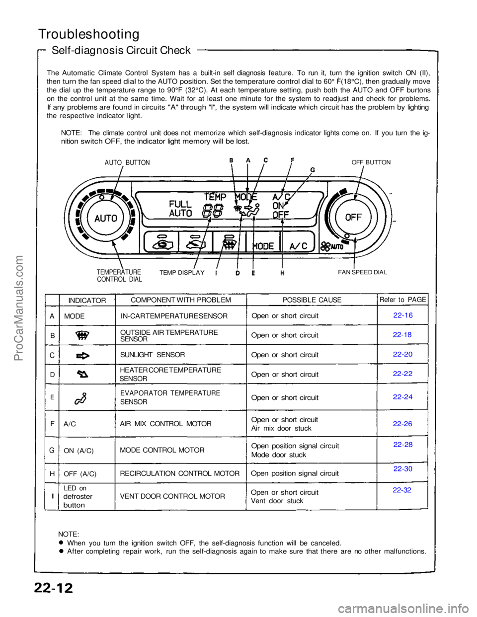
The Automatic Climate Control System has a built-in self diagnosis feature. To run it, turn the ignition switch ON (II),
then turn the fan speed dial to the AUTO position. Set the temperature control dial to 60° F(18°C), then gradually move
0
th
e
dial up the temperature range to 90°F (32°C). At each temperatu\
re setting, push both the AUTO and OFF burtons
o
n
the control unit at the same time. Wait for at least one minute for the\
system to readjust and check for problems.
If any problems are found in circuits "A" through "I", the system will indicate which circuit has the problem by lighting
the respective indicator light.
NOTE: The climate control unit does not memorize which self-diagnosis indicator lights come on. If you turn the ig-
nition switch OFF, the indicator light memory will be lost.
AUTO BUTTON
OFF BUTTON
TEMPERATURE CONTROL DIAL
TEMP DISPLAY
FAN SPEED DIAL
NOTE:
When you turn the ignition switch OFF, the self-diagnosis function will be canceled. After completing repair work, run the self-diagnosis again to make sure that there are no other malfunctions.COMPONENT WITH PROBLEM
IN-CAR TEMPERATURE SENSOR
OUTSIDE AIR TEMPERATURE
SENSOR
SUNLIGHT SENSOR
HEATER CORE TEMPERATURE
SENSOR
EVAPORATOR TEMPERATURE
SENSOR
AIR MIX CONTROL MOTOR
MODE CONTROL MOTOR
RECIRCULATION CONTROL MOTOR
VENT DOOR CONTROL MOTOR
POSSIBLE CAUSE
Open or short circuit
Open or short circuit
Open or short circuit
Open or short circuit
Open or short circuit
Open or short circuit
Air mix door stuck
Open position signal circuit
Mode door stuck
Open position signal circuit
Open or short circuit
Vent door stuck
Refer to PAGE
22-16
22-1
8
22-20
22-22
22-24
22-2
6
22-28
22-30
22-32
INDICATOR
MODE
A/C
ON
(A/C)
OFF
(A/C)
LED on
defroster
button
A
B
C
D
E
F
G
H
I
ProCarManuals.com
Page 692 of 1640
Air Mix Control Motor
Replacement
1. Disconnect the heater valve cable from the air mix control motor.
HEATER VALVE
CABLE
AIR MIX CONTROL
MOTOR
2. Remove the three screws and the air mix control
motor.
AIR MIX CONTROL
MOTOR
3. Install the air mix centrol motor in the reverse order of removal, then apply battery voltage (see page
22-57) and watch the door move.
Make sure that the air mix door moves smoothly
without binding.
Make sure the motor doesn't pull the air mix
door too far.
4. If necessary, to adjust the heater valve cable:
Set the air mix control motor at COOL position
(see page 22-57) with the cable disconnected
at the valve.
Hold the end of the cable housing against the
stop on the cable. Then snap the clamp down
ove
r
the housing.
After adjusting the cable, make sure that the air
mix control motor still moves smoothly without
binding.
STOP
CLAMP
HEATER VALVE
CABLE
AIR MIX CONTROLMOTOR
ProCarManuals.com
Page 700 of 1640
Heater Core Temperature Sensor
Removal
Disconnect the connector, remove the clamp and the
heater core temperature sensor.
CLAMP
HEATER CORE
TEMPERATURE
SENSOR
Compare the resistance reading between the terminals
of the heater core temperature sensor with specifica-
tions shown in the following graph: It should be within
specification.
NOTE: Dip the sensor in ice water, and measure the
resistance. Then pour hot water on the sensor, and
check for change in resistance.
CAUTION: The sensor uses a thermistor which
can be damaged if high current is applied to it
during testing. Therefore, use a circuit tester
that puts out a measuring current of 1 mA or
less.
TestProCarManuals.com
Page 709 of 1640

Heater-Evaporator Unit
Replacement
SRS components are located in this area. Review the SRS
component locations, precautions, and procedures in the
SRS section (24) before performing repairs or service.
1.
Remove
the
blower
unit
(see
page
22-67 ('93-'96),
63('91-'92)).
2. When the engine is cool, drain the engine coolant from the radiator (see section 10).
Do not remove the radiator cap when
the engine is hot; the engine coolant is under
pressure and could severely scald you.
CAUTION: Engine coolant will damage paint. Quick-
ly rinse any spilled engine coolant off painted sur-
faces.
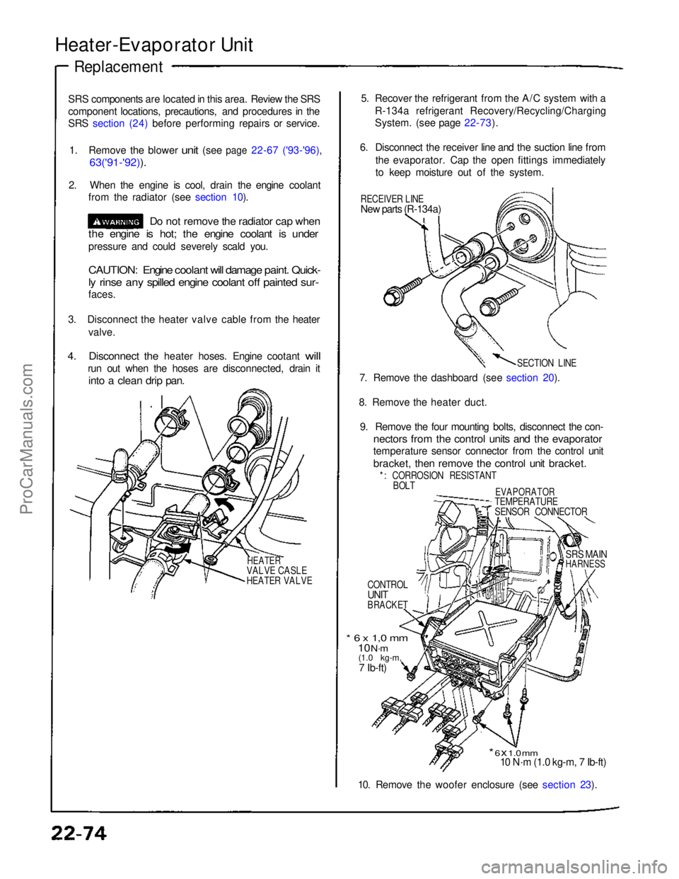
3. Disconnect the heater valve cable from the heater valve.
4.
Disconnect
the
heater hoses. Engine cootant
will
run out when the hoses are disconnected, drain it
into a clean drip pan.
HEATER
VALVE CASLE
HEATER VALVE
5. Recover the refrigerant from the A/C system with a
R-134a refrigerant Recovery/Recycling/Charging
System. (see page 22-73).
6. Disconnect the receiver line and the suction line from the evaporator. Cap the open fittings immediately
to keep moisture out of the system.
RECEIVER LINE
New parts (R-134a)
SECTION LINE
7. Remove the dashboard (see section 20).
8. Remove the heater duct. 9. Remove the four mounting bolts, disconnect the con-
nectors from the control units and the evaporator
temperature sensor connector from the control unit
bracket, then remove the control unit bracket.
*: CORROSION RESISTANT BOLT
EVAPORATOR
TEMPERATURE
SENSOR CONNECTOR
CONTROL
UNIT
BRACKET
SRS MAIN
HARNESS
* 6 x 1,0 mm
10 N·m
(1.0 kg-m,
7 Ib-ft)
* 6 x 1.0 mm
10 N·m (1.0 kg-m, 7 Ib-ft)
10. Remove the woofer enclosure (see section 23).ProCarManuals.com
Page 710 of 1640

11. Disconnect the connectors from all the control
motors and sensors attached to the heater-
evaporator unit.
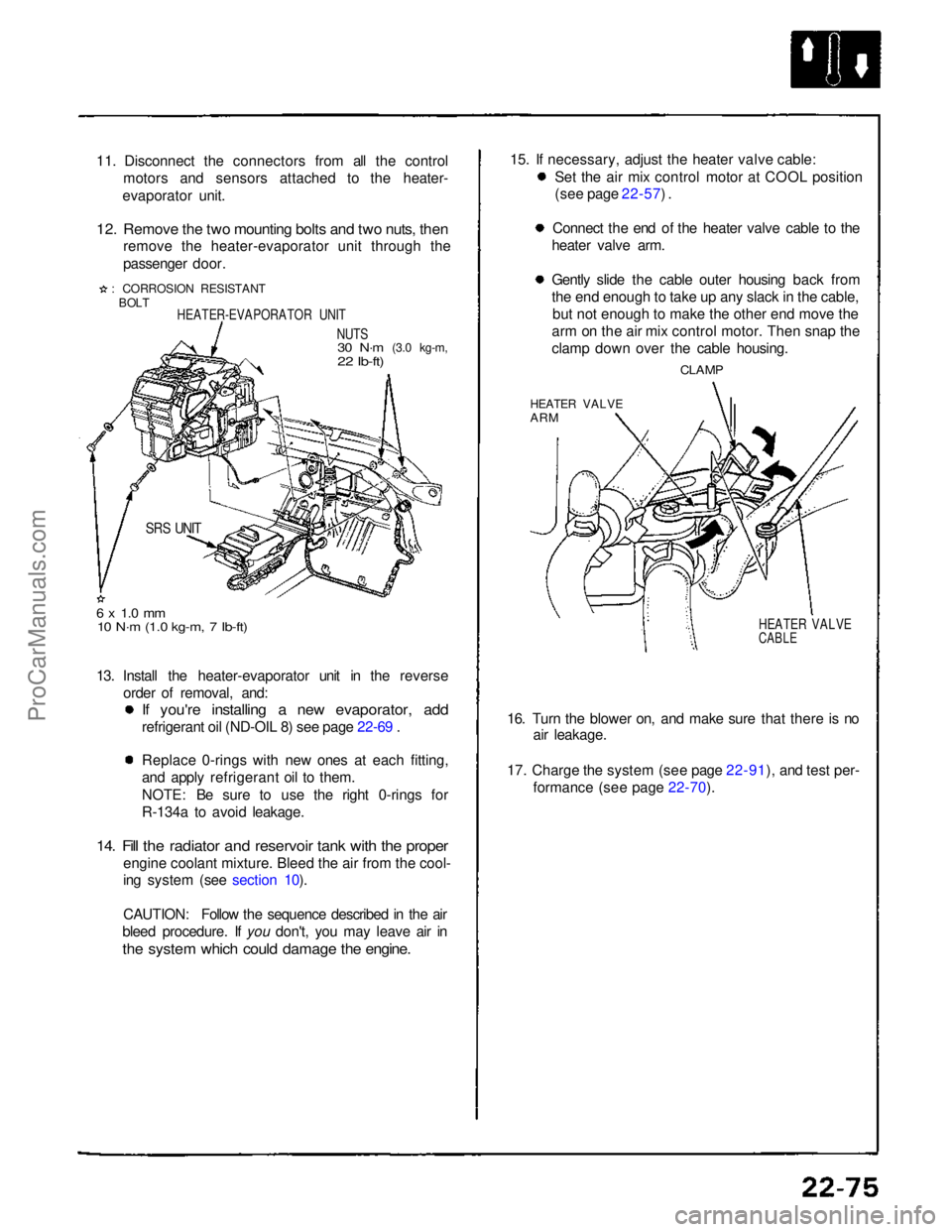
12. Remove the two mounting bolts and two nuts, then
remove the heater-evaporator unit through the
passenger door.
: CORROSION RESISTANT
BOLT
HEATER-EVAPORATOR UNIT
NUTS
30 N·m
(3.0 kg-m,
22 Ib-ft)
SRS UNIT
6 x 1.0 mm
10 N·m (1.0 kg-m, 7 Ib-ft)
13. Install the heater-evaporator unit in the reverse order of removal, and:
If you're installing a new evaporator, add
refrigerant oil (ND-OIL 8) see page 22-69 .
Replace 0-rings with new ones at each fitting,
and apply refrigerant oil to them.
NOTE: Be sure to use the right 0-rings for
R-134a to avoid leakage.
14. Fill the radiator and reservoir tank with the proper
engine coolant mixture. Bleed the air from the cool-
ing system (see section 10).
CAUTION: Follow the sequence described in the air
bleed procedure. If you don't, you may leave air in
the system which could damage the engine.
15. If necessary, adjust the heater valve cable:
Set the air mix control motor at COOL position
(see page 22-57) .
Connect the end of the heater valve cable to the
heater valve arm. Gently slide the cable outer housing back from
the end enough to take up any slack in the cable,
bu
t not enough to make the other end move the
arm on the air mix control motor. Then snap the
clamp down over the cable housing.
CLAMP
HEATER VALVE
ARM
HEATER VALVE
CABLE
16. Turn the blower on, and make sure that there is no air leakage.
17. Charge the system (see page 22-91), and test per- formance (see page 22-70).ProCarManuals.com
Page 711 of 1640
Heater-Evaporator Uni t
Overhau l
1. Remov e th e heate r cor e cover , remov e th e pip e clamp , the n pul l ou t th e heate r core .
2 . Remov e th e lowe r hal f o f th e housing , the n remov e th e evaporator .
3 . Remov e th e expansio n valv e i f necessary .
HEATER COR E PIPE CLAM P
AI R MI X DOO R
LOWE R HAL F
OF TH E HOUSIN G
CAPILLAR Y TUB E
SUCTIO N LIN E
*EVAPORATOR
The expansio n valv e capillar y tub emus t b e touchin g th e suctio n line .
New par t fo r R-134a .
4. Assembl e th e heater-evaporato r uni t i n th e revers e orde r o f disassembly . Hol d th e expansio n valv e capillar y tub e
dow n agains t th e suctio n line , an d wra p i t wit h tap e t o hol d i t there .
EXPANSIO N VALV E HEATE
R COR E
COVE R
TAPE
SUCTIO N LIN E
ProCarManuals.com
Page 984 of 1640
Cooling
Cooling System
Two cooling systems are employed:
An antifreeze/water system with the radiator mounted in the front of the vehicle.
An air-cooling system driven by a fan mounted in the engine compartment.
BLEEDER
RADIATOR
BLEEDER
WATER VALVE
HEATER CORE
DRAIN
DRAINS
BLEEDER
ENGINE DRAIN
WATER PUMP
ENGINE OIL
COOLER
ENGINE DRAIN
FAST IDLE THERMO VALVE
IDLE AIR CONTROL (IAC) VALVE
BREATHER PIPE
THROTTLE
BODY
THERMOSTAT
TEMPERATURE SWITCH
ENGINE COOLANT
BLEEDER
EXPANSION
TANKProCarManuals.com
Page 989 of 1640
Engine Removal/Installation
(cont'd)
18. Remove the breather pipe, then remove the air in- take duct and the air cleaner case.
6 x 1.0 mm
10 N .
m (1.0kg-m, 7 Ib-ft)
AIR CLEANER
CASE
BREATHER PIPE
19. Disconnect the evaporative emission (EVAP) con- trol canister hose from throttle body.
20. Disconnect the brake booster vacuum hose from the intake manifold.
EVAP CONTROL CANISTER
EVAP CONTROL
CANISTER
HOSE
BRAKE BOOSTER
VACUUM HOSE 21. Disconnect the two engine wire harness connec-
tors from the side wire harness at left side of
engine compartment, and remove the engine wireharness terminal and the starter cable terminal
from the main fuse box and clamps.
22. Remove the ground cable from the transmission. MAIN FUSE BOX
6x1.0
mm
10 N .
m
(1.0 kg-m,
7 Ib-ft)
ENGINE WIRE
HARNESS
23. Remove the water hoses and the heater hose from the water passage.
HEATER HOSE
WATER HOSES
: CORROSION RESISTANT BOLTProCarManuals.com