Page 1017 of 1640
(cont'd)
29. Remove the water passage.
O-RINGS
Replace.
CONNECTING PIPE
WATER PASSAGE
8 x
1.25
mm
22N .
m (2.2 kg-m. 16 Ib-ft)
30. Remove the cylinder head covers.
31. Turn the crankshaft so that the No. 1 piston is at top dead center (page 6-25, 26).
32.
Install
a
brace
under
the
engine, then
tilt
the
engine approximately 5° using a jack (page 6-24).
33. Remove the alternator bracket.
8 x
1.25
mm
22N.m (2.2 kg-m, 16 Ib-ft)
10 x
1.25
mm
45N.m (4.5 kg-m.
33 Ib-ft)
ALTERNATOR
BRACKET
24. Remove the bolt from the side engine mount, then
push the side mounting bracket into the housing of
the body (page 5-27).
25. Remove the transmission mount. 26. Remove the alternator bracket stiffener (page 6-24).
27. Disconnect the knock sensor connectors, then re- move the wire holder.
6 x 1.0 mm
12N .
m (1.2 kg-m. 9 Ib-ft)
KNOCK SENSOR
WIRE HOLDER
28. Remove the heater hose and the water hoses.
WATER HOSES
HEATER HOSEProCarManuals.com
Page 1084 of 1640

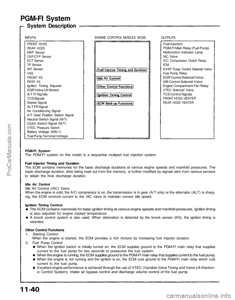
PGM-FI System
System Description
INPUTS
ENGINE CONTROL MODULE (ECM)
OUTPUTS
FRONT HO2S
REAR HO2S
MAP Sensor
CKP/CYP Sensor
ECT Sensor
TP Sensor
IAT Sensor
VSS
FRONT KS
REAR KS
Ignition Timing Adjuster
EGR Valve Lift Sensor
A/T Fl Signals
TCS Signals
Starter Signal
ALT FR Signal
Air Conditioning Signal
A/T Gear Position Switch Signal
Neutral Switch Signal (M/T)
Clutch Switch Signal (M/T)
VTEC Pressure Switch
Battery Voltage (IGN.1)
Fuel Pump Terminal Voltage
Fuel Injectors
PGM-FI Main Relay (Fuel Pump)
Malfunction Indicator Lamp
IAC Valve
A/C Compressor Clutch Relay
ICM
EVAP Purge Control Solenoid Valve
Fuel Pump Relay
EGR Control Solenoid Valve
IAB Control Solenoid Valve
Engine Compartment Fan Relay
VTEC Solenoid Valve
TCS Control Signals
FRONT HO2S HEATER
REAR HO2S HEATER
PGM-FI System
The PGM-FI system on this model is a sequential multiport fuel injection system.
Fuel Injector Timing and Duration
The ECM contains memories for the basic discharge durations at various engine speeds and manifold pressures. The
basic discharge duration, after being read out from the memory, is further modified by signals sent from various sensors
to obtain the final discharge duration.
Idle Air Control
Idle Air Control (IAC) Valve
When the engine is cold, the A/C compressor is on, the transmission is in gear (A/T only) or the alternator (ALT) is charg-
ing, the ECM controls current to the IAC valve to maintain correct idle speed.
Ignition Timing Control
The ECM contains memories for basic ignition timing at various engine speeds and manifold pressures. Ignition timing
is also adjusted for engine coolant temperature.
A knock control system is also used. When detonation is detected by the knock sensor (KS), the ignition timing is
retarded.
Other Control Functions
1. Starting Control
When the engine is started, the ECM provides a rich mixture by increasing fuel injector duration.
2. Fuel Pump Control
When the ignition switch is initially turned on, the ECM supplies ground to the PGM-FI main relay that supplies
current to the fuel pump for two seconds to pressurize the fuel system.
When the engine is running, the ECM supplies ground to the PGM-FI main relay that supplies current to the fuel pump.
When the engine is not running and the ignition is on, the ECM cuts ground to the PGM-FI main relay which cuts
current to the fuel pump.
Excellent engine performance is achieved through the use of VTEC (Variable Valve Timing and Valve Lift Electron-
ic Control System), intake air bypass control and discharge volume control of the fuel pump.ProCarManuals.com
Page 1350 of 1640
EPS Control unit
Replacement
CAUTION: Be careful not to damage the SRS wire
harnesses when servicing the control unit. 1. Remove the dashboard lower cover and glove box
and disconnect the light connector.
3. Disconnect the connectors from the EPS control
unit by removing the wire harness band.
EPS CONTROL UNIT
4. Remove the power window control unit by pulling it
toward you, then remove the EPS control unit.
5. Installation is the reverse of the removal procedure.
NOTE: Turn the ignition switch ON and check the
EPS indicator light for operation.
HEATER DUCT
2. Move the heater duct right then remove the heater
duct.
DASHBOARD LOWER COVER
GLOVE BOX
EPS CONTROL UNIT
POWER WINDOW CONTROL
UNIT
10 N ·
m
(1.0 kg-m, 7 Ib-ft)
All SRS wire harnesses and connectors
are colored yellow. Do not use electrical test equipment
on these circuits.
CONNECTORSProCarManuals.com
Page 1371 of 1640

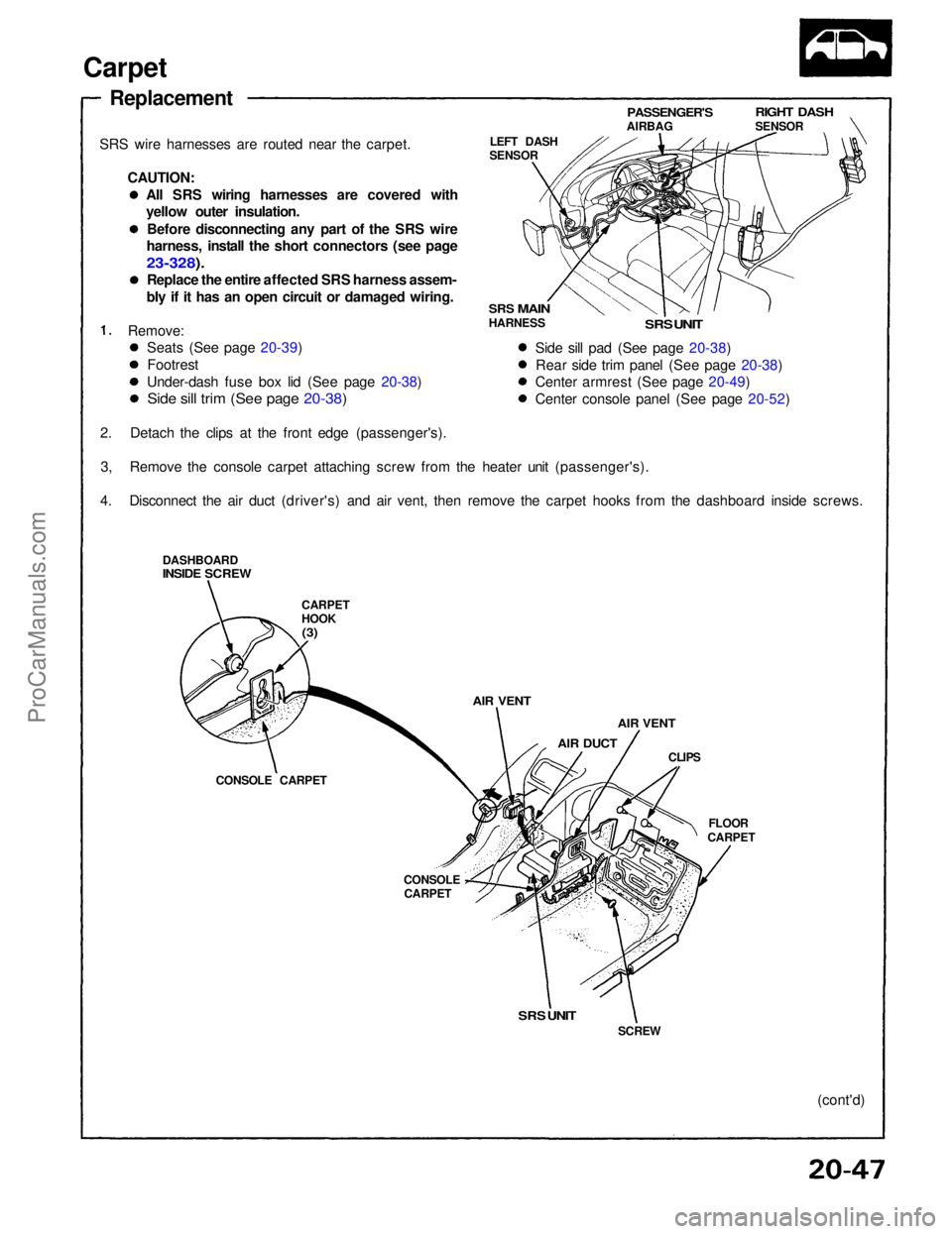
Carpet
Replacement
SRS wire harnesses are routed near the carpet. CAUTION:
Remove:
2. Detach the clips at the front edge (passenger's). 3, Remove the console carpet attaching screw from the heater unit (passenger's).
4. Disconnect the air duct (driver's) and air vent, then remove the carpet hooks from the dashboard inside screws.
DASHBOARD
INSIDE SCREW
CARPET
HOOK
(3)
AIR VENT
AIR DUCT
AIR VENT
CLIPS
FLOOR
CARPET
CONSOLE
CARPET
CONSOLE CARPET LEFT DASH
SENSOR
PASSENGER'S
AIRBAG
RIGHT DASH
SENSOR
SRS
MAIN
HARNESS
SRS UNIT
Side sill pad (See page 20-38) Rear side trim panel (See page 20-38)
Center armrest (See page 20-49)
Center console panel (See page 20-52)
SRS UNIT
SCREW
(cont'd)
Seats (See page 20-39)
Footrest
Under-dash fuse box lid (See page 20-38)
Side sill trim (See page 20-38)
All SRS wiring harnesses are covered with
yellow outer insulation.
Before disconnecting any part of the SRS wire
harness, install the short connectors (see page
23-328).
Replace the entire affected SRS harness assem-
bly if it has an open circuit or damaged wiring.ProCarManuals.com
Page 1372 of 1640
Carpet
Replacement (cont'd)
5. Pull up the retainers, then remove the floor carpets.
6. Remove the console carpets.
FOOTREST
CONSOLE
CARPETS
SRS UNIT
FOOTREST MOUNTING
BOLTS
RETAINERS
RETAINERS
FLOOR CARPETS
SEAT HARNESSES
7. Installation is the reverse of the removal procedure.
NOTE:
Take care not to damage, wrinkle or twist the carpets.
Make sure the air vents are connected into the heater unit and air duct.
Make sure the seat harnesses are routed correctly.ProCarManuals.com
Page 1528 of 1640
System Description
Tailpipe Emission
The emission control system includes a three-way catalytic converter, exhaust gas recirculation (EGR) system,
crankcase ventilation system and evaporative control
system.
The emission control system is designed to meet federal and
state emission standards.
Inspection
Do not smoke during this procedure. Keep
any open flame away from your work area.
1. Starting the engine and warm it up to normal operating temperature by driving the car on theroad.
2. Connect a tachometer.
3. Check idle speed and adjust the idle speed, if necessary (page 11-84).
4. Warm up and calibrate the CO meter according to the meter manufacturer's instructions.
5. Check idle CO with the headlights, heater blower, rear window defogger, cooling fan, and air conditioner off.
CO meter should indicate 0.1 % maximum.ProCarManuals.com
Page 1579 of 1640

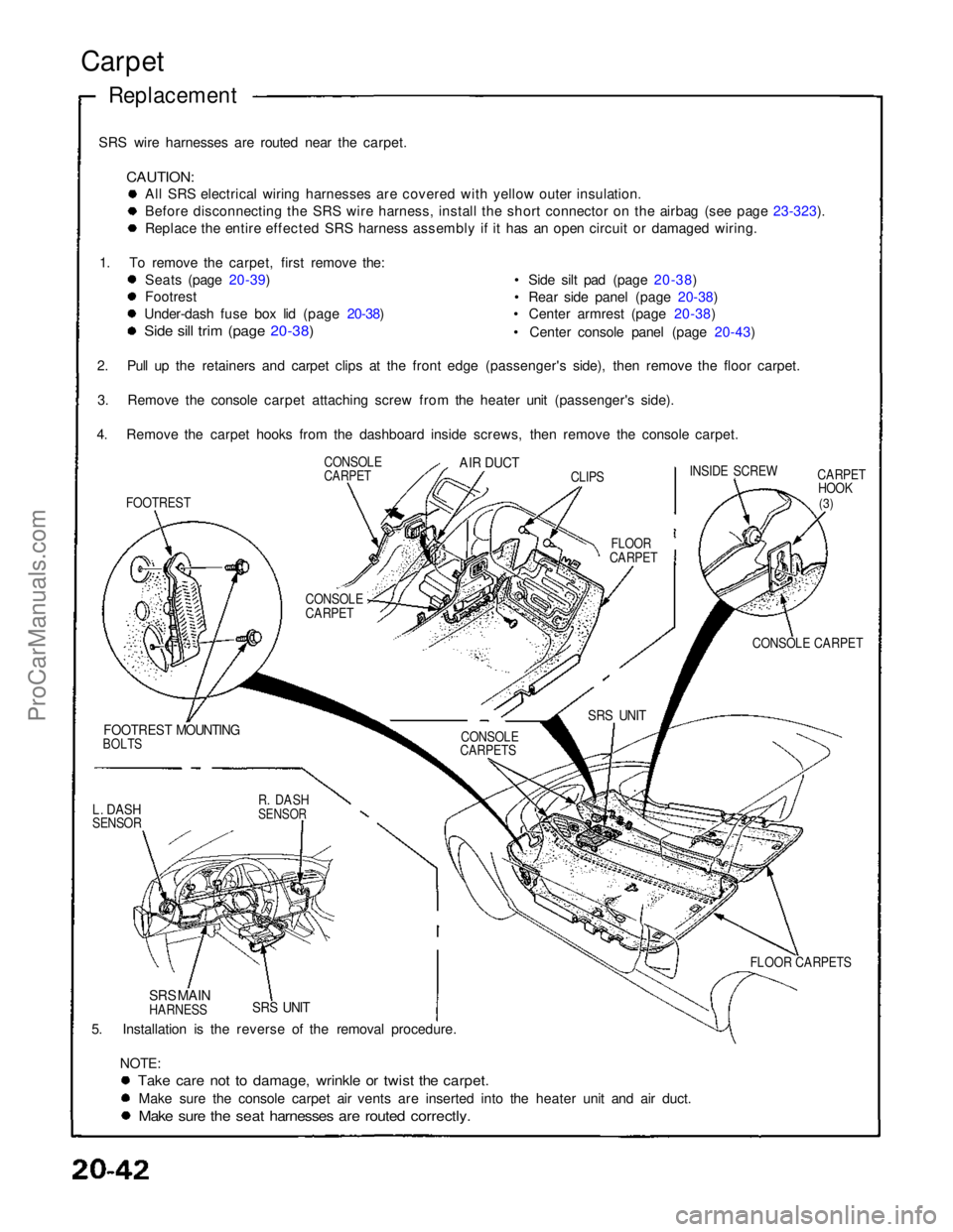
SRS wire harnesses are routed near the carpet.
CAUTION:
All SRS electrical wiring harnesses are covered with yellow outer insulation.
Before disconnecting the SRS wire harness, install the short connector on the airbag (see page 23-323).
Replace the entire effected SRS harness assembly if it has an open circuit or damaged wiring.
1. To remove the carpet, first remove the: Seats (page 20-39)
Footrest
Under-dash fuse box lid (page 20-38)
Side sill trim (page 20-38)
• Side silt pad (page 20-38)
• Rear side panel (page 20-38)
• Center armrest (page 20-38)
• Center console panel (page 20-43)
CARPETHOOK
(3)
CONSOLE CARPET
FOOTREST MOUNTING
BOLTS
5. Installation is the reverse of the removal procedure. NOTE:
Take care not to damage, wrinkle or twist the carpet.
Make sure the console carpet air vents are inserted into the heater unit and air duct.
Make sure the seat harnesses are routed correctly.
Carpet
Replacement
SRS UNIT
SRS MAIN
HARNESS FLOOR CARPETS
SRS UNIT
CONSOLE
CARPETS
CONSOLE
CARPET
FLOOR
CARPET INSIDE SCREW
CLIPS
AIR DUCT
CONSOLE
CARPET
FOOTREST
2. Pull up the retainers and carpet clips at the front edge (passenger's side), then remove the floor carpet.
3. Remove the console carpet attaching screw from the heater unit (passenger's side).
4. Remove the carpet hooks from the dashboard inside screws, then remove the console carpet.
L. DASH
SENSOR
R. DASH
SENSORProCarManuals.com
Page 1580 of 1640

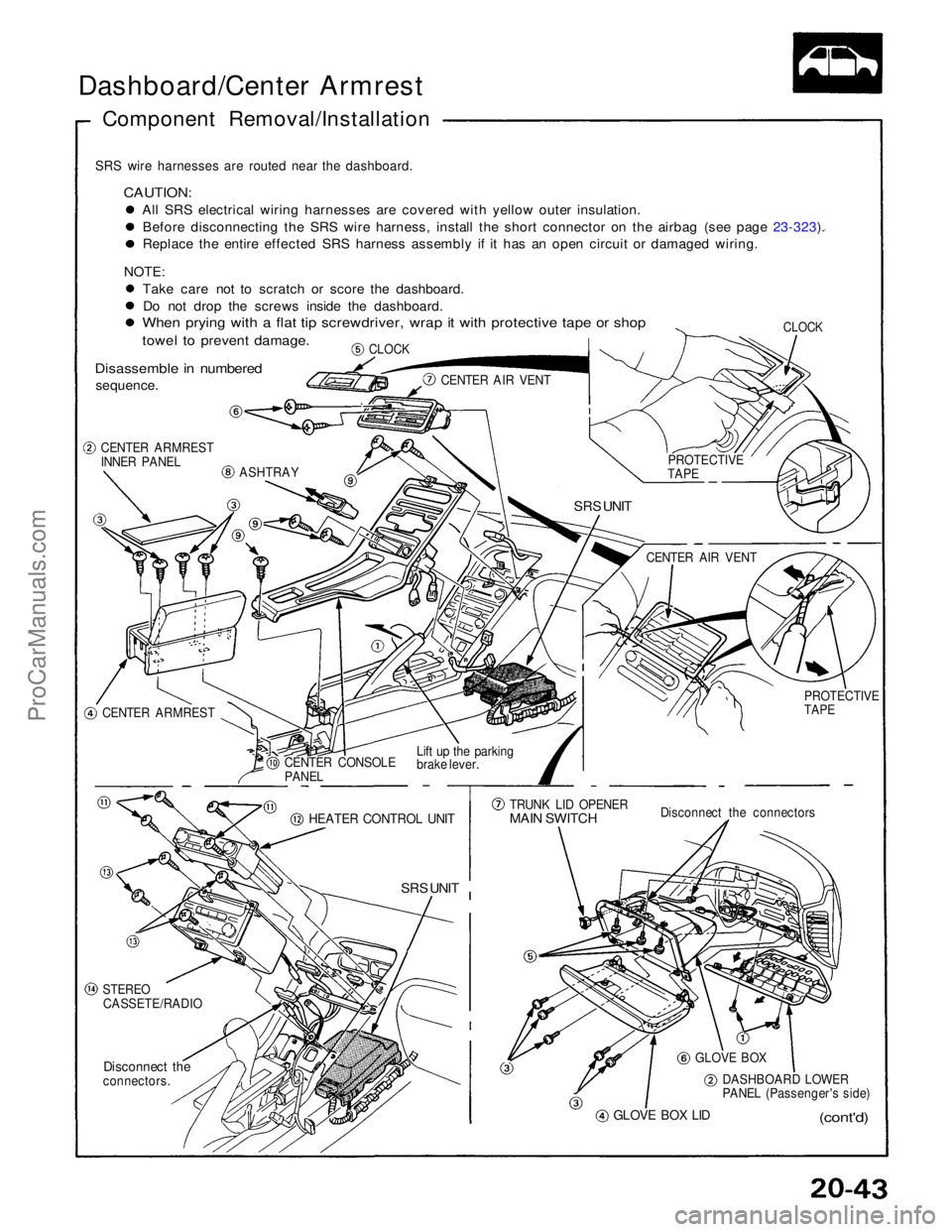
Dashboard/Center Armrest
Component Removal/Installation
SRS wire harnesses are routed near the dashboard.
CAUTION:
All SRS electrical wiring harnesses are covered with yellow outer insulation.Before disconnecting the SRS wire harness, install the short connector on the airbag (see page 23-323). Replace the entire effected SRS harness assembly if it has an open circuit or damaged wiring.
NOTE: Take care not to scratch or score the dashboard.Do not drop the screws inside the dashboard.
When prying with a flat tip screwdriver, wrap it with protective tape or shop
towel to prevent damage.
Disassemble in numbered
sequence.
CLOCK
CLOCK
CENTER AIR VENT
CENTER ARMREST
INNER PANEL
ASHTRAY
SRS UNIT
CENTER ARMREST CENTER CONSOLE
PANEL
Lift up the parking
brake lever.
HEATER CONTROL UNIT
SRS UNIT
STEREO
CASSETE/RADIO
Disconnect the
connectors.
GLOVE BOX LID
(cont'd)
DASHBOARD LOWER
PANEL (Passenger's side)
GLOVE BOX
Disconnect the connectors
TRUNK LID OPENER
MAIN SWITCH
PROTECTIVE
TAPE
CENTER AIR VENT
PROTECTIVE
TAPEProCarManuals.com