1990 VOLKSWAGEN CORRADO check oil
[x] Cancel search: check oilPage 439 of 906

D - ADJUSTMENTS
Article Text (p. 2)
1990 Volkswagen Corrado
For Volkswagen Technical Site: http://vw.belcom.ru
Copyright © 1998 Mitchell Repair Information Company, LLC
Thursday, March 23, 2000 09:43PM
connected, timing mark on flywheel should appear at pointer in hole.
NOTE: Before checking engine timing, raise engine speed above 2100
RPM at least 4 times. This must be done each time ignition
is turned off and restarted to clear ECU memory and by-pass
hot-start, fast-idle function.
3) If an adjustment is needed, turn ignition off and loosen
distributor hold-down bolt (2.0L has 2 hold-down bolts) just enough to
move distributor by hand. Start engine and allow to idle. Turn
distributor until timing mark is aligned with pointer in bellhousing.
4) Stop engine and tighten hold down bolt to 18 ft. lbs. (24
N.m). On 2.0L tighten hold-down bolts to 87 INCH lbs. (10 N.m). Check
and readjust if necessary and install plastic plug in inspection hole.
VANAGON
1) Engine oil temperature must be 176ø F (80ø C). Connect
timing light and tachometer. Start engine and allow to idle. Check
ignition timing at 800-1000 RPM.
NOTE: Before checking engine timing, raise engine speed above 2100
RPM at least 4 times. This must be done each time ignition
is turned off and restarted to clear ECU memory and by-pass
hot-start, fast-idle function.
2) If an adjustment is needed, turn ignition off and loosen
distributor hold-down bolt just enough to move distributor by hand.
Remove connectors from idle stabilizer by squeezing connectors then
pulling apart. Plug idle stabilizer connectors together.
3) Start and allow engine to idle. Turn distributor until
notch on V-belt pulley matches separation in case. Set timing and RPM.
Reconnect electrical connectors to idle stabilizer. Tighten
distributor clamp bolt.
IGNITION TIMING TABLE
IGNITION TIMING (Degrees BTDC @ RPM)
ÄÄÄÄÄÄÄÄÄÄÄÄÄÄÄÄÄÄÄÄÄÄÄÄÄÄÄÄÄÄÄÄÄÄÄÄÄÄÄÄÄÄÄÄÄÄÄÄÄÄÄÄÄÄÄÄÄÄÄÄÄÄÄÄÄÄÄÄÄÄApplication Checking Adjusting
1.8L ..................... 4-8 @ 870-930 ........... 5-7 @ 870-930
2.0L ..................... 4-8 @ 770-830 ........... 5-7 @ 770-830
2.1L ..................... 4-8 @ 800-900 ........... 5-7 @ 800-900
ÄÄÄÄÄÄÄÄÄÄÄÄÄÄÄÄÄÄÄÄÄÄÄÄÄÄÄÄÄÄÄÄÄÄÄÄÄÄÄÄÄÄÄÄÄÄÄÄÄÄÄÄÄÄÄÄÄÄÄÄÄÄÄÄÄÄÄÄÄÄ COLD (FAST) IDLE
Fast idle RPM is not adjustable.
IDLE SPEED & MIXTURE
Page 440 of 906
D - ADJUSTMENTS
Article Text (p. 3)
1990 Volkswagen Corrado
For Volkswagen Technical Site: http://vw.belcom.ru
Copyright © 1998 Mitchell Repair Information Company, LLC
Thursday, March 23, 2000 09:43PM
NOTE: Mixture adjustment is NOT a part of normal tune-up procedure
and should not be performed unless mixture control unit is
replaced or vehicle fails emissions testing.
NOTE: Ensure system pressure is correct before attempting idle
speed or mixture adjustment.
IDLE SPEED & MIXTURE ADJUSTMENT
FOX (CIS-E) & JETTA GLI 2.0L (CIS-MOTRONIC)
1) Ignition timing and idle speed must be checked before CO
is adjusted. See CHECKING & ADJUSTING under IGNITION TIMING. With
ignition timing properly adjusted, check and adjust idle speed,
differential pressure regulator current and idle mixture. Repeat the
adjustments until all occur at the same time.
2) Warm engine to normal operating temperature. Radiator fan
must come on at least once and engine oil temperature must be at least
176øF (80øC). Turn off all electrical equipment, including A/C and
radiator fan. Disconnect all fuel pressure test equipment (if
installed). If injection lines have been removed or replaced, run
engine several times to 3000 RPM for about 2 minutes.
3) Ensure idle switch is properly adjusted. Check that
auxiliary air regulator valve is fully closed. Pinch shut the hose
leading from the idle speed boost valve(s). Remove temperature sensor
harness connector from the temperature sensor. Pull crankcase breather
hoses off valve cover and air filter, vent to atmosphere.
4) Remove suction hose from carbon canister. Disconnect "T"
fitting from carbon canister at air intake boot. On Fox models only,
remove connector from coolant temperature sensor and install 15,000-
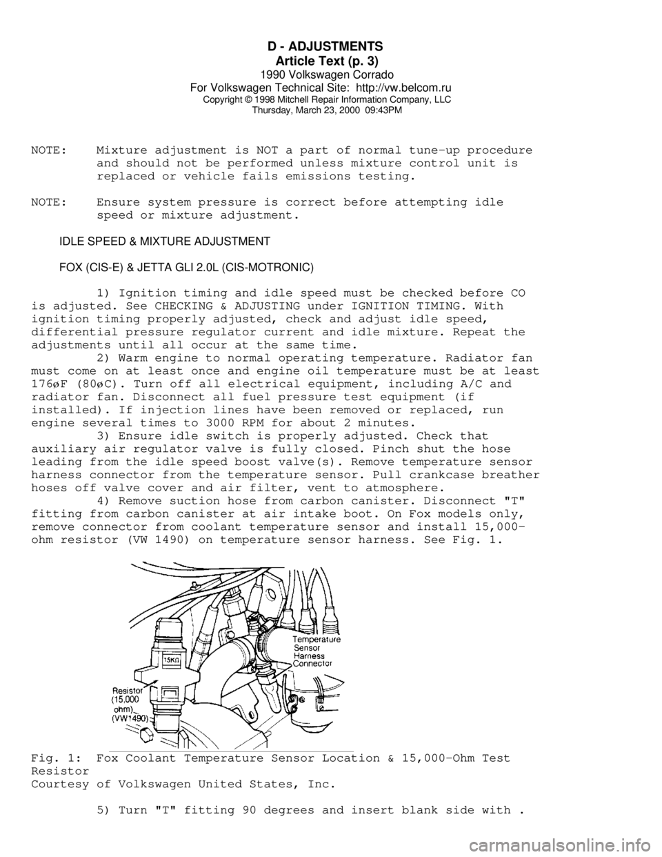
ohm resistor (VW 1490) on temperature sensor harness. See Fig. 1.Fig. 1: Fox Coolant Temperature Sensor Location & 15,000-Ohm Test
Resistor
Courtesy of Volkswagen United States, Inc.
5) Turn "T" fitting 90 degrees and insert blank side with .
Page 442 of 906
D - ADJUSTMENTS
Article Text (p. 5)
1990 Volkswagen Corrado
For Volkswagen Technical Site: http://vw.belcom.ru
Copyright © 1998 Mitchell Repair Information Company, LLC
Thursday, March 23, 2000 09:43PM
8) Connect adapter between connector and regulator. Connect
multimeter to adapter and turn switch to DCA 200 milliamp-range. Read
and compare current (4-16 milliamps) and CO values to specifications.
Turn engine off.
9) If CO reading is more than 1.2% at current reading of 4-16
milliamps, check for exhaust system leaks, ignition timing, injector
inserts for leaks, and fuel distributor for uneven fuel distribution.
If required, seal injector inserts with sealing compound and tighten
to 15 ft. lbs. (20 N.m).
10) If current reading is less than 4 milliamps or more than
16 milliamps, adjustment must be made with CO adjustment screw as
follows: remove boot from mixture control unit. Center punch hole in
CO adjusting hole and drill a 3/32" hole to a depth of 5/32" (4 mm).
DO NOT drill completely through as adjustment screw will be damaged.
11) Install a 1/8" sheet metal screw and remove plug using
pliers. Start engine and run at idle. Adjust current reading to 10
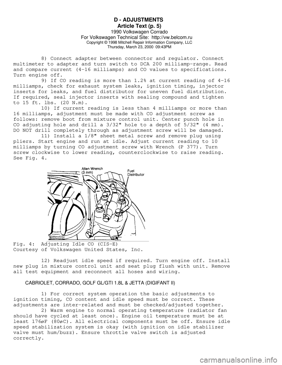
milliamps by turning CO adjustment screw with Wrench (P 377). Turn
screw clockwise to lower reading, counterclockwise to raise reading.
See Fig. 4.Fig. 4: Adjusting Idle CO (CIS-E)
Courtesy of Volkswagen United States, Inc.
12) Readjust idle speed if required. Turn engine off. Install
new plug in mixture control unit and seat plug flush with unit. Remove
all test equipment and reconnect all hoses and wiring.
CABRIOLET, CORRADO, GOLF GL/GTI 1.8L & JETTA (DIGIFANT II)
1) For correct system operation the basic adjustments to
ignition timing, CO content and idle speed must be correct. These
adjustments are inter-related and must be checked/adjusted together.
2) Warm engine to normal operating temperature (radiator fan
should have cycled at least once). Engine oil temperature must be at
least 176øF (80øC). All electrical components must be off. Ensure idle
speed stabilization system is okay (with ignition on idle stabilizer
valve must hum/buzz). Ensure throttle valve switch is adjusted
correctly.
Page 443 of 906
D - ADJUSTMENTS
Article Text (p. 6)
1990 Volkswagen Corrado
For Volkswagen Technical Site: http://vw.belcom.ru
Copyright © 1998 Mitchell Repair Information Company, LLC
Thursday, March 23, 2000 09:43PM
NOTE: Before checking engine timing, raise engine speed above 2100
RPM at least 4 times. This must be done each time ignition
is turned off and restarted to clear ECU memory and by-pass
hot-start, fast-idle function.
3) Connect an inductive tachometer or Tester (VW 1367) to
alternator, Test Lead (VW 1473) to ignition coil, and timing light
lead to No. 1 spark plug wire. See Fig. 2. Start engine and ensure
engine speed and timing are correct. If not, adjust to specification.
4) Remove the Blue cap from the CO tap tube rising from the
exhaust manifold and connect exhaust gas analyzer. Disconnect the
coolant sensor harness connector. Raise the oil dipstick slightly to
vent crankcase. Disconnect and plug the crankcase ventilation hose.
Start engine and raise engine speed to 2100 RPM at least 4 times.
Check idle, adjust if incorrect. check CO is correct. See IDLE & CO
LEVEL table. If CO adjustment is needed, the idle mixture screw anti-
tamper plug must be remove from the top of the air flow sensor.
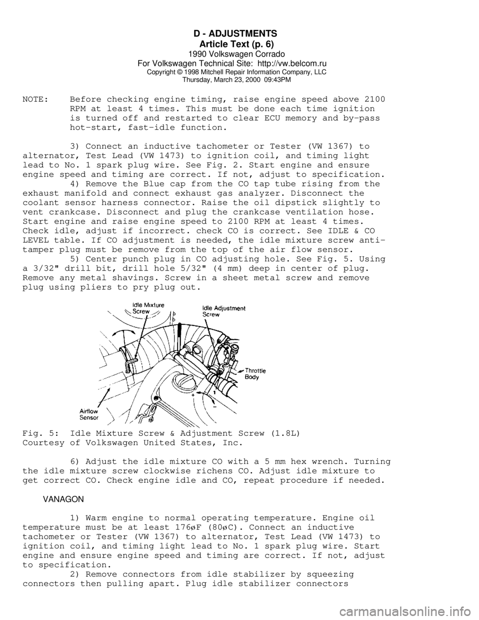
5) Center punch plug in CO adjusting hole. See Fig. 5. Using
a 3/32" drill bit, drill hole 5/32" (4 mm) deep in center of plug.
Remove any metal shavings. Screw in a sheet metal screw and remove
plug using pliers to pry plug out.Fig. 5: Idle Mixture Screw & Adjustment Screw (1.8L)
Courtesy of Volkswagen United States, Inc.
6) Adjust the idle mixture CO with a 5 mm hex wrench. Turning
the idle mixture screw clockwise richens CO. Adjust idle mixture to
get correct CO. Check engine idle and CO, repeat procedure if needed.
VANAGON
1) Warm engine to normal operating temperature. Engine oil
temperature must be at least 176øF (80øC). Connect an inductive
tachometer or Tester (VW 1367) to alternator, Test Lead (VW 1473) to
ignition coil, and timing light lead to No. 1 spark plug wire. Start
engine and ensure engine speed and timing are correct. If not, adjust
to specification.
2) Remove connectors from idle stabilizer by squeezing
connectors then pulling apart. Plug idle stabilizer connectors
Page 513 of 906

ENGINE OVERHAUL PROCEDURES - GENERAL INFORMATION
Article Text (p. 4)
1990 Volkswagen Corrado
For Volkswagen Technical Site: http://vw.belcom.ru
Copyright © 1998 Mitchell Repair Information Company, LLC
Thursday, March 23, 2000 09:44PM
specifications for the vehicle being repaired.
SHEET METAL PARTS
Examples of sheet metal parts are the rocker covers, front
and side covers, oil pan and bellhousing dust cover. Glass bead
blasting or hot tank may be used for cleaning.
Ensure all mating surfaces are flat. Deformed surfaces should
be straightened. Check all sheet metal parts for cracks and dents.
INTAKE & EXHAUST MANIFOLDS
Using solvent cleaning or bead blasting, clean manifolds for
inspection. If the intake manifold has an exhaust crossover, all
carbon deposits must be removed. Inspect manifolds for cracks, burned
or eroded areas, corrosion and damage to fasteners.
Exhaust heat and products of combustion cause threads of
fasteners to corrode. Replace studs and bolts as necessary. On "V"
type intake manifolds, the sheet metal oil shield must be removed for
proper cleaning and inspection. Ensure that all manifold parting
surfaces are flat and free of burrs.
CYLINDER HEAD REPLACEMENT
* PLEASE READ THIS FIRST *
NOTE: Always refer to appropriate engine overhaul article in the
ENGINES section for complete overhaul procedures and
specifications for the vehicle being repaired.
REMOVAL
Remove intake and exhaust manifolds and valve cover. Cylinder
head and camshaft carrier bolts (if equipped), should be removed only
when the engine is cold. On many aluminum cylinder heads, removal
while hot will cause cylinder head warpage. Mark rocker arm or
overhead cam components for location.
Remove rocker arm components or overhead cam components.
Components must be installed in original location. Individual design
rocker arms may utilize shafts, ball-type pedestal mounts or no rocker
arms. For all design types, wire components together and identify
according to the corresponding valve. Remove cylinder head bolts.
Note length and location. Some applications require cylinder head
bolts be removed in proper sequence to prevent cylinder head damage.
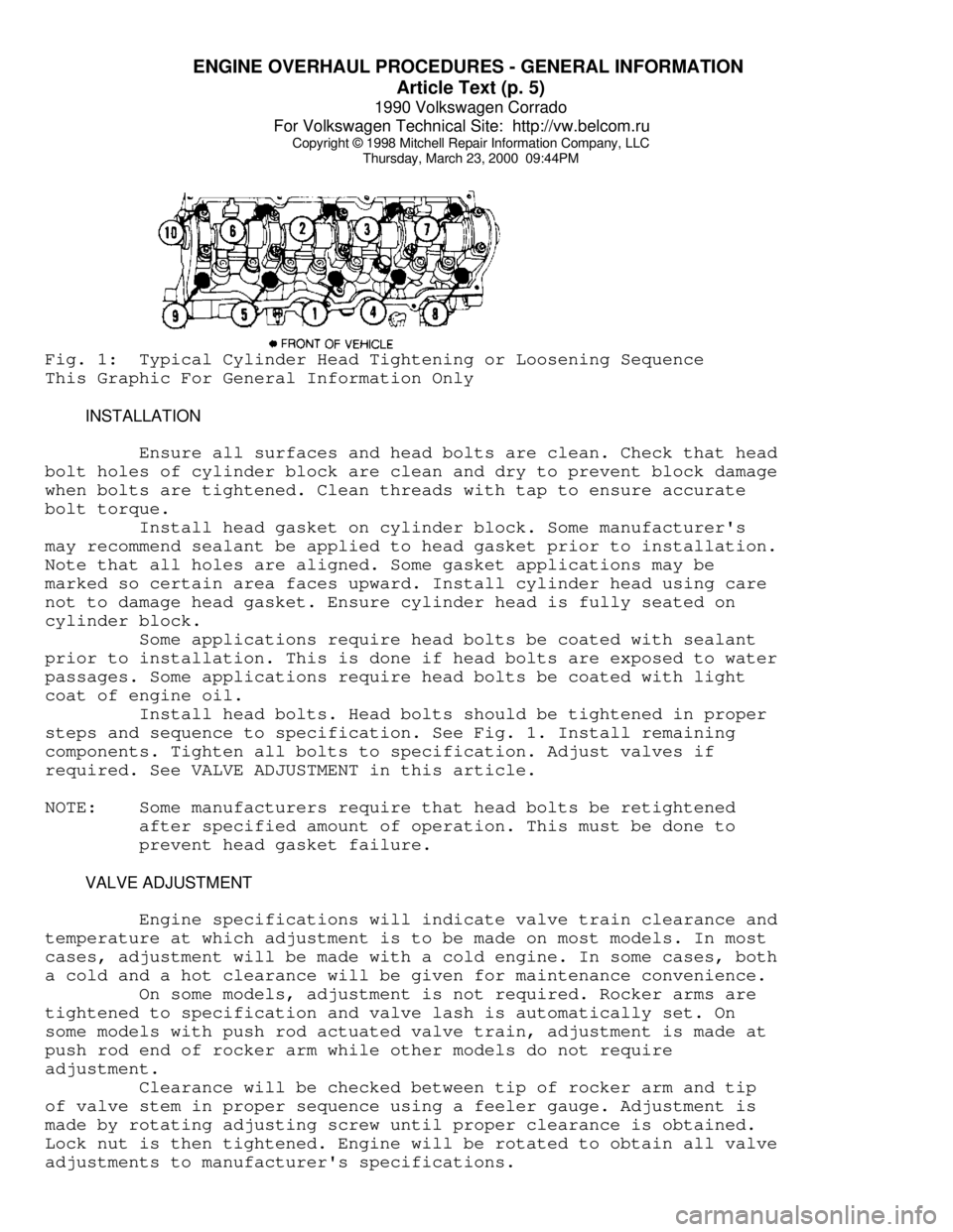
See Fig. 1. Remove cylinder head.
Page 514 of 906
ENGINE OVERHAUL PROCEDURES - GENERAL INFORMATION
Article Text (p. 5)
1990 Volkswagen Corrado
For Volkswagen Technical Site: http://vw.belcom.ru
Copyright © 1998 Mitchell Repair Information Company, LLC
Thursday, March 23, 2000 09:44PMFig. 1: Typical Cylinder Head Tightening or Loosening Sequence
This Graphic For General Information Only
INSTALLATION
Ensure all surfaces and head bolts are clean. Check that head
bolt holes of cylinder block are clean and dry to prevent block damage
when bolts are tightened. Clean threads with tap to ensure accurate
bolt torque.
Install head gasket on cylinder block. Some manufacturer's
may recommend sealant be applied to head gasket prior to installation.
Note that all holes are aligned. Some gasket applications may be
marked so certain area faces upward. Install cylinder head using care
not to damage head gasket. Ensure cylinder head is fully seated on
cylinder block.
Some applications require head bolts be coated with sealant
prior to installation. This is done if head bolts are exposed to water
passages. Some applications require head bolts be coated with light
coat of engine oil.
Install head bolts. Head bolts should be tightened in proper
steps and sequence to specification. See Fig. 1. Install remaining
components. Tighten all bolts to specification. Adjust valves if
required. See VALVE ADJUSTMENT in this article.
NOTE: Some manufacturers require that head bolts be retightened
after specified amount of operation. This must be done to
prevent head gasket failure.
VALVE ADJUSTMENT
Engine specifications will indicate valve train clearance and
temperature at which adjustment is to be made on most models. In most
cases, adjustment will be made with a cold engine. In some cases, both
a cold and a hot clearance will be given for maintenance convenience.
On some models, adjustment is not required. Rocker arms are
tightened to specification and valve lash is automatically set. On
some models with push rod actuated valve train, adjustment is made at
push rod end of rocker arm while other models do not require
adjustment.
Clearance will be checked between tip of rocker arm and tip
of valve stem in proper sequence using a feeler gauge. Adjustment is
made by rotating adjusting screw until proper clearance is obtained.
Lock nut is then tightened. Engine will be rotated to obtain all valve
adjustments to manufacturer's specifications.
Page 516 of 906
ENGINE OVERHAUL PROCEDURES - GENERAL INFORMATION
Article Text (p. 7)
1990 Volkswagen Corrado
For Volkswagen Technical Site: http://vw.belcom.ru
Copyright © 1998 Mitchell Repair Information Company, LLC
Thursday, March 23, 2000 09:44PM
CLEANING & INSPECTION
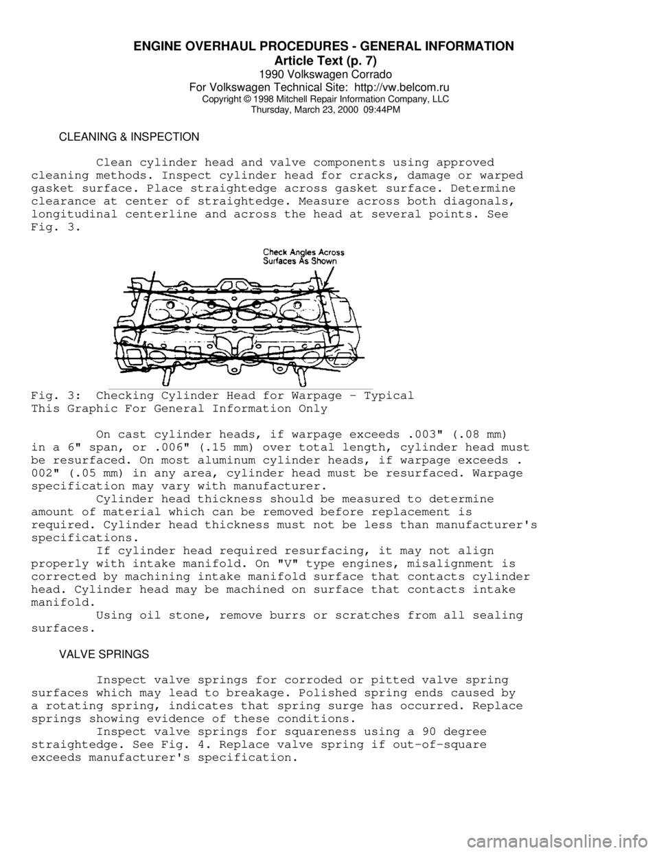
Clean cylinder head and valve components using approved
cleaning methods. Inspect cylinder head for cracks, damage or warped
gasket surface. Place straightedge across gasket surface. Determine
clearance at center of straightedge. Measure across both diagonals,
longitudinal centerline and across the head at several points. See
Fig. 3.Fig. 3: Checking Cylinder Head for Warpage - Typical
This Graphic For General Information Only
On cast cylinder heads, if warpage exceeds .003" (.08 mm)
in a 6" span, or .006" (.15 mm) over total length, cylinder head must
be resurfaced. On most aluminum cylinder heads, if warpage exceeds .
002" (.05 mm) in any area, cylinder head must be resurfaced. Warpage
specification may vary with manufacturer.
Cylinder head thickness should be measured to determine
amount of material which can be removed before replacement is
required. Cylinder head thickness must not be less than manufacturer's
specifications.
If cylinder head required resurfacing, it may not align
properly with intake manifold. On "V" type engines, misalignment is
corrected by machining intake manifold surface that contacts cylinder
head. Cylinder head may be machined on surface that contacts intake
manifold.
Using oil stone, remove burrs or scratches from all sealing
surfaces.
VALVE SPRINGS
Inspect valve springs for corroded or pitted valve spring
surfaces which may lead to breakage. Polished spring ends caused by
a rotating spring, indicates that spring surge has occurred. Replace
springs showing evidence of these conditions.
Inspect valve springs for squareness using a 90 degree
straightedge. See Fig. 4. Replace valve spring if out-of-square
exceeds manufacturer's specification.
Page 521 of 906
ENGINE OVERHAUL PROCEDURES - GENERAL INFORMATION
Article Text (p. 12)
1990 Volkswagen Corrado
For Volkswagen Technical Site: http://vw.belcom.ru
Copyright © 1998 Mitchell Repair Information Company, LLC
Thursday, March 23, 2000 09:44PM
Valve Seat Replacement
Replacement of valve seat inserts is done by cutting out
the old insert and machining an oversize insert bore. Replacement
oversize insert is usually chilled and the cylinder head is sometimes
warmed. Valve seat is pressed into the head. This operation requires
specialized machine shop equipment.
Valve Seat Concentricity
Using dial gauge, install gauge pilot in valve guide.
Position gauge arm on the valve seat. Adjust dial indicator to zero.
Rotate arm 360 degrees and note reading. Runout should not exceed
specification.
To check valve-to-valve seat concentricity, coat valve face
lightly with Prussian Blue dye. Install valve and rotate it on valve
seat. If pattern is even and entire seat is coated at valve contact
point, valve is concentric with the seat.
REASSEMBLY
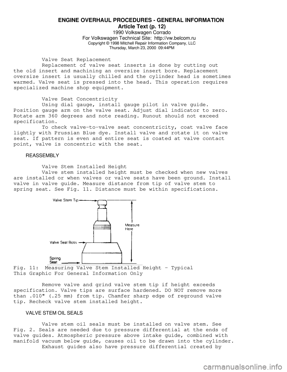
Valve Stem Installed Height
Valve stem installed height must be checked when new valves
are installed or when valves or valve seats have been ground. Install
valve in valve guide. Measure distance from tip of valve stem to
spring seat. See Fig. 11. Distance must be within specifications.Fig. 11: Measuring Valve Stem Installed Height - Typical
This Graphic For General Information Only
Remove valve and grind valve stem tip if height exceeds
specification. Valve tips are surface hardened. DO NOT remove more
than .010" (.25 mm) from tip. Chamfer sharp edge of reground valve
tip. Recheck valve stem installed height.
VALVE STEM OIL SEALS
Valve stem oil seals must be installed on valve stem. See
Fig. 2. Seals are needed due to pressure differential at the ends of
valve guides. Atmospheric pressure above intake guide, combined with
manifold vacuum below guide, causes oil to be drawn into the cylinder.
Exhaust guides also have pressure differential created by